2007 NISSAN TIIDA jack
[x] Cancel search: jackPage 2932 of 5883
![NISSAN TIIDA 2007 Service Repair Manual OIL PAN
EM-285
< ON-VEHICLE REPAIR >[K9K]
C
D
E
F
G
H
I
J
K
L
MA
EM
N
P O
10. Remove oil pan and transaxle joint bolts.
11. Support the engine bottom of the oil pan with a transmission jack
etc.
12. R NISSAN TIIDA 2007 Service Repair Manual OIL PAN
EM-285
< ON-VEHICLE REPAIR >[K9K]
C
D
E
F
G
H
I
J
K
L
MA
EM
N
P O
10. Remove oil pan and transaxle joint bolts.
11. Support the engine bottom of the oil pan with a transmission jack
etc.
12. R](/manual-img/5/57395/w960_57395-2931.png)
OIL PAN
EM-285
< ON-VEHICLE REPAIR >[K9K]
C
D
E
F
G
H
I
J
K
L
MA
EM
N
P O
10. Remove oil pan and transaxle joint bolts.
11. Support the engine bottom of the oil pan with a transmission jack
etc.
12. Remove oil pan bolts in reverse order as shown.
13. Insert seal cutter [SST: KV10111100 (—)] between upper oil pan
and cylinder block. Slide tool by tapping on the side of the tool
with a hammer.
CAUTION:
Exercise care not to damage mating surface.
14. Remove oil pan.
INSTALLATION
Installation is in the reverse order of removal.
MBIB1039E
MBIB0575E
MBIB1257E
SEM365EA
Page 2949 of 5883
![NISSAN TIIDA 2007 Service Repair Manual EM-302
< REMOVAL AND INSTALLATION >[K9K]
ENGINE ASSEMBLY
REMOVAL AND INSTALLATION
ENGINE ASSEMBLY
Exploded ViewINFOID:0000000001381504
Removal and InstallationINFOID:0000000001381505
WARNING:
Situat NISSAN TIIDA 2007 Service Repair Manual EM-302
< REMOVAL AND INSTALLATION >[K9K]
ENGINE ASSEMBLY
REMOVAL AND INSTALLATION
ENGINE ASSEMBLY
Exploded ViewINFOID:0000000001381504
Removal and InstallationINFOID:0000000001381505
WARNING:
Situat](/manual-img/5/57395/w960_57395-2948.png)
EM-302
< REMOVAL AND INSTALLATION >[K9K]
ENGINE ASSEMBLY
REMOVAL AND INSTALLATION
ENGINE ASSEMBLY
Exploded ViewINFOID:0000000001381504
Removal and InstallationINFOID:0000000001381505
WARNING:
Situate vehicle on a flat and solid surface.
Place chocks at front and back of rear wheels.
For engines not equipped with engine slingers, attach proper slingers and bolts described in PARTS
CATALOG.
CAUTION:
Always be careful to work safely, avoid forceful or uninstructed operations.
Do not start working until exhaust system and coolant are cool enough.
If items or work required are not covered by the main engine section, follow the procedures in the
applicable sections.
Always use the support point specified for lifting.
Use either 2-pole lift type or separate type lift as best you can. If board-on type is used for unavoid-
able reasons, support at the rear axle jacking point with transmission jack or similar tool before
starting work, in preparation for the backward shift of center of gravity.
For supporting points for lifting and jacking rear axle, refer to GI-48, "
Garage Jack and Safety Stand
and 2-Pole Lift" or GI-49, "Board-On Lift".
REMOVAL
Description of Work
1. Engine mounting insulator LH 2. Engine mounting frame support LH 3. Engine mounting bracket LH
4. Upper torque rod 5. Engine mounting insulator RH 6. Engine mounting bracket RH (upper)
7. Engine mounting bracket RH (lower) 8. Lower torque rod bracket 9. Lower torque rod
: Vehicle front
AWBIA0162GB
Page 2951 of 5883
![NISSAN TIIDA 2007 Service Repair Manual EM-304
< REMOVAL AND INSTALLATION >[K9K]
ENGINE ASSEMBLY
1. Install engine slingers (1) into front right of cylinder head and
engine slinger (2) into rear left of cylinder head.
2. Remove upper torque NISSAN TIIDA 2007 Service Repair Manual EM-304
< REMOVAL AND INSTALLATION >[K9K]
ENGINE ASSEMBLY
1. Install engine slingers (1) into front right of cylinder head and
engine slinger (2) into rear left of cylinder head.
2. Remove upper torque](/manual-img/5/57395/w960_57395-2950.png)
EM-304
< REMOVAL AND INSTALLATION >[K9K]
ENGINE ASSEMBLY
1. Install engine slingers (1) into front right of cylinder head and
engine slinger (2) into rear left of cylinder head.
2. Remove upper torque rod.
3. Use a manual lift table caddy (commercial service tool) or equiv-
alently rigid tool such as a jack or trestle. Securely support bot-
tom of engine and transaxle.
CAUTION:
Put a piece of wood or something similar at the supporting
surface to secure a stable condition.
4. Remove RH and LH engine mounting bolts.
5. Remove engine and transaxle assembly from vehicle downward
by carefully operating supporting tools.
CAUTION:
During the operation, make sure that no part interferes with body side.
Before and during this lifting, always check if any harnesses are left connected.
During the removal operation, always be careful to prevent vehicle from falling off the lift due to
changes in the center of gravity.
If necessary, support vehicle by setting a jack or equivalent tool at the rear.
Separation Work
CAUTION:
During the operation, secure the engine by placing a piece of wood under the engine oil pan and tran-
saxle and lift the engine using a suitable tool.
1. Remove starter motor.
2. Separate engine and transaxle.
3. Lift the engine with a suitable tool and separate the engine from the transaxle assembly. Refer to EM-302,
"Exploded View".
INSTALLATION
Installation is in the reverse order of removal.
Do not allow oil to get on mounting insulator. Be careful not to damage mounting insulator.
When installation directions are specified, install parts according to the direction marks on them referring to
exploded views.
Make sure that each mounting insulator is seated properly, and tighten mounting bolts and nuts.
InspectionINFOID:0000000001381506
INSPECTION AFTER INSTALLATION
Before starting engine check the levels of coolant, lubricants and oils. Fill to the specified level.
Before starting engine, bleed air from fuel piping. Refer to EM-287, "
Removal and Installation".
Run engine to check for unusual noise and vibration.
Warm up engine thoroughly to make sure there is no leakage of coolant, lubricants, oil, fuel and exhaust
gas.
Bleed air from passages in pipes and tubes of applicable lines.
MBIB9022E
Page 3109 of 5883
SQUEAK AND RATTLE TROUBLE DIAGNOSIS
EXT-5
< ON-VEHICLE MAINTENANCE >
C
D
E
F
G
H
I
J
L
MA
B
EXT
N
O
P
If possible, drive the vehicle with the customer until the noise is duplicated. Note any additional information on
the Diagnostic Worksheet regarding the conditions or location of the noise. This information can be used to
duplicate the same conditions when you confirm the repair.
If the noise can be duplicated easily during the test drive, to help identify the source of the noise, try to dupli-
cate the noise with the vehicle stopped by doing one or all of the following:
Close a door.
Tap or push/pull around the area where the noise appears to be coming from.
Rev the engine.
Use a floor jack to recreate vehicle “twist”.
At idle, apply engine load (electrical load, half-clutch on M/T model, drive position on A/T model).
Raise the vehicle on a hoist and hit a tire with a rubber hammer.
Drive the vehicle and attempt to duplicate the conditions the customer states exist when the noise occurs.
If it is difficult to duplicate the noise, drive the vehicle slowly on an undulating or rough road to stress the
vehicle body.
CHECK RELATED SERVICE BULLETINS
After verifying the customer concern or symptom, check ASIST for Technical Service Bulletins (TSBs) related
to that concern or symptom.
If a TSB relates to the symptom, follow the procedure to repair the noise.
LOCATE THE NOISE AND IDENTIFY THE ROOT CAUSE
1. Narrow down the noise to a general area. To help pinpoint the source of the noise, use a listening tool
(Chassis Ear: J-39570, Engine Ear: J-39565 and mechanics stethoscope).
2. Narrow down the noise to a more specific area and identify the cause of the noise by:
Removing the components in the area that you suspect the noise is coming from.
Do not use too much force when removing clips and fasteners, otherwise clips and fasteners
can be broken or lost during the repair, resulting in the creation of new noise.
Tapping or pushing/pulling the component that you suspect is causing the noise.
Do not tap or push/pull the component with excessive force, otherwise the noise will be elimi-
nated only temporarily.
Feeling for a vibration with your hand by touching the component(s) that you suspect is (are) causing
the noise.
Placing a piece of paper between components that you suspect are causing the noise.
Looking for loose components and contact marks.
Refer to EXT-6, "
Generic Squeak and Rattle Troubleshooting".
REPAIR THE CAUSE
If the cause is a loose component, tighten the component securely.
If the cause is insufficient clearance between components:
- Separate components by repositioning or loosening and retightening the component, if possible.
- Insulate components with a suitable insulator such as urethane pads, foam blocks, felt cloth tape or ure-
thane tape. A Squeak and Rattle Kit is available through your authorized NISSAN Parts Department.
CAUTION:
Do not use excessive force as many components are constructed of plastic and may be damaged.
Always check with the Parts Department for the latest parts information.
The following materials are contained in the Squeak and Rattle Kit. Each item can be ordered separately as
needed.
URETHANE PADS [1.5 mm (0.059 in) thick]
Insulates connectors, harness, etc.
76268-9E005: 100 x 135 mm (3.94 x 5.31 in)/76884-71L01: 60 x 85 mm (2.36 x 3.35 in)/76884-71L02: 15 x 25
mm (0.59 x 0.98 in)
INSULATOR (Foam blocks)
Insulates components from contact. Can be used to fill space behind a panel.
73982-9E000: 45 mm (1.77 in) thick, 50 x 50 mm (1.97 x 1.97 in)/73982-50Y00: 10 mm (0.39 in) thick, 50 x 50
mm (1.97 x 1.97 in)
INSULATOR (Light foam block)
80845-71L00: 30 mm (1.18 in) thick, 30 x 50 mm (1.18 x 1.97 in)
FELT CLOTH TAPE
Used to insulate where movement does not occur. Ideal for instrument panel applications.
68370-4B000: 15 x 25 mm (0.59 x 0.98 in) pad/68239-13E00: 5 mm (0.20 in) wide tape roll
The following materials, not found in the kit, can also be used to repair squeaks and rattles.
Page 3110 of 5883
EXT-6
< ON-VEHICLE MAINTENANCE >
SQUEAK AND RATTLE TROUBLE DIAGNOSIS
UHMW (TEFLON) TAPE
Insulates where slight movement is present. Ideal for instrument panel applications.
SILICONE GREASE
Used in place of UHMW tape that will be visible or not fit.
Note: Will only last a few months.
SILICONE SPRAY
Use when grease cannot be applied.
DUCT TAPE
Use to eliminate movement.
CONFIRM THE REPAIR
Confirm that the cause of a noise is repaired by test driving the vehicle. Operate the vehicle under the same
conditions as when the noise originally occurred. Refer to the notes on the Diagnostic Worksheet.
Generic Squeak and Rattle TroubleshootingINFOID:0000000001568922
Refer to Table of Contents for specific component removal and installation information.
INSTRUMENT PANEL
Most incidents are caused by contact and movement between:
1. The cluster lid A and instrument panel
2. Acrylic lens and combination meter housing
3. Instrument panel to front pillar garnish
4. Instrument panel to windshield
5. Instrument panel pins
6. Wiring harnesses behind the combination meter
7. A/C defroster duct and duct joint
These incidents can usually be located by tapping or moving the components to duplicate the noise or by
pressing on the components while driving to stop the noise. Most of these incidents can be repaired by apply-
ing felt cloth tape or silicone spray (in hard to reach areas). Urethane pads can be used to insulate wiring har-
ness.
CAUTION:
Do not use silicone spray to isolate a squeak or rattle. If you saturate the area with silicone, you will
not be able to recheck the repair.
CENTER CONSOLE
Components to pay attention to include:
1. Shifter assembly cover to finisher
2. A/C control unit and cluster lid C
3. Wiring harnesses behind audio and A/C control unit
The instrument panel repair and isolation procedures also apply to the center console.
DOORS
Pay attention to the:
1. Finisher and inner panel making a slapping noise
2. Inside handle escutcheon to door finisher
3. Wiring harnesses tapping
4. Door striker out of alignment causing a popping noise on starts and stops
Tapping or moving the components or pressing on them while driving to duplicate the conditions can isolate
many of these incidents. You can usually insulate the areas with felt cloth tape or insulator foam blocks from
the Squeak and Rattle Kit to repair the noise.
TRUNK
Trunk noises are often caused by a loose jack or loose items put into the trunk by the owner.
In addition look for:
1. Trunk lid bumpers out of adjustment
2. Trunk lid striker out of adjustment
3. The trunk lid torsion bars knocking together
Page 3171 of 5883
FUEL TANK
FL-11
< ON-VEHICLE REPAIR >
C
D
E
F
G
H
I
J
K
L
MA
FL
N
P O
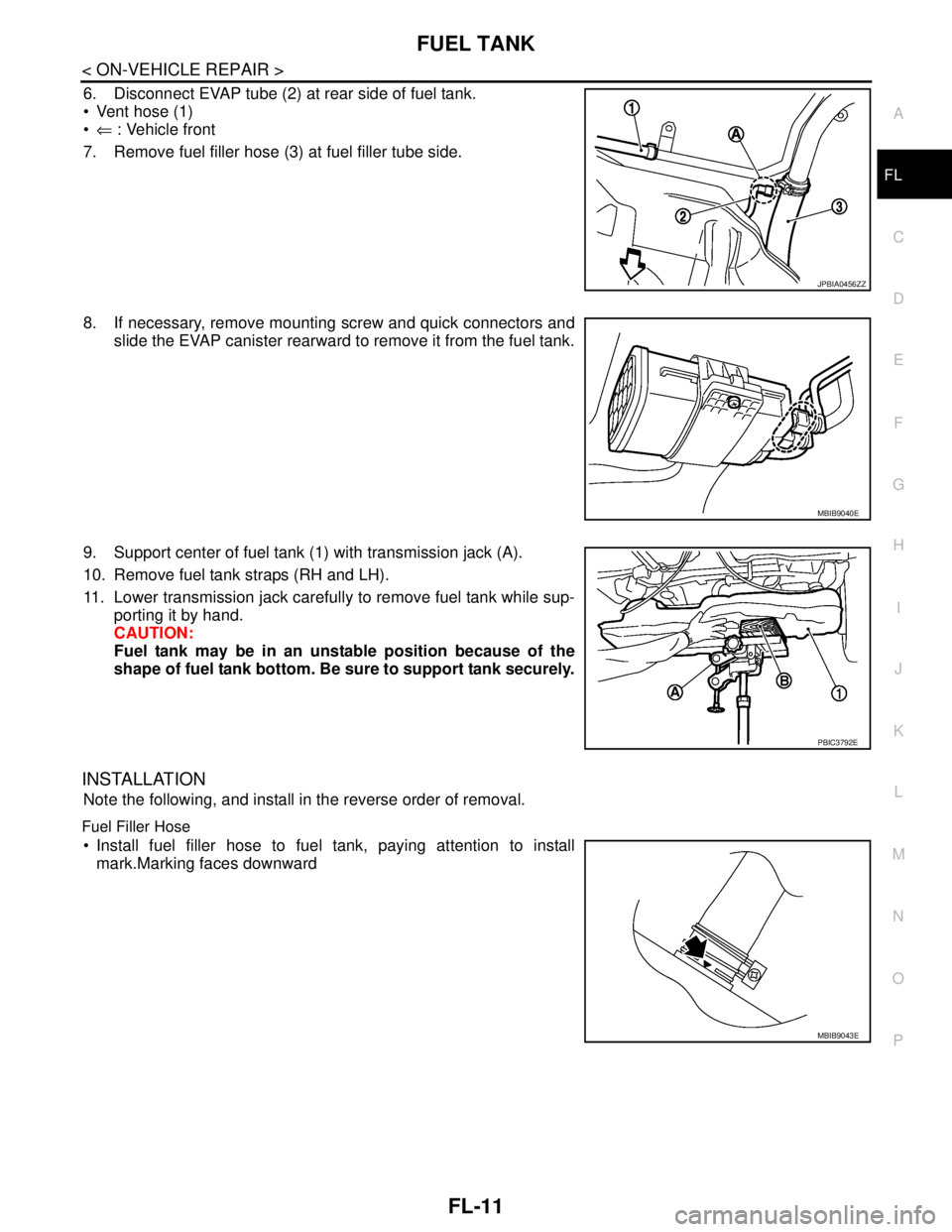
6. Disconnect EVAP tube (2) at rear side of fuel tank.
Vent hose (1)
⇐ : Vehicle front
7. Remove fuel filler hose (3) at fuel filler tube side.
8. If necessary, remove mounting screw and quick connectors and
slide the EVAP canister rearward to remove it from the fuel tank.
9. Support center of fuel tank (1) with transmission jack (A).
10. Remove fuel tank straps (RH and LH).
11. Lower transmission jack carefully to remove fuel tank while sup-
porting it by hand.
CAUTION:
Fuel tank may be in an unstable position because of the
shape of fuel tank bottom. Be sure to support tank securely.
INSTALLATION
Note the following, and install in the reverse order of removal.
Fuel Filler Hose
Install fuel filler hose to fuel tank, paying attention to install
mark.Marking faces downward
JPBIA0456ZZ
MBIB9040E
PBIC3792E
MBIB9043E
Page 3175 of 5883
FUEL TANK
FL-15
< ON-VEHICLE REPAIR >
C
D
E
F
G
H
I
J
K
L
MA
FL
N
P O
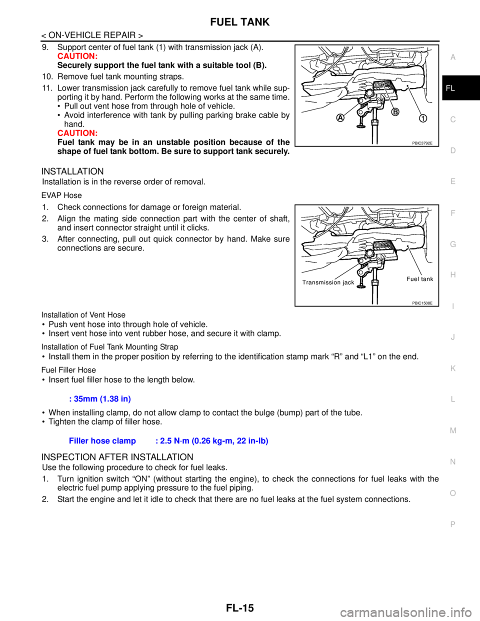
9. Support center of fuel tank (1) with transmission jack (A).
CAUTION:
Securely support the fuel tank with a suitable tool (B).
10. Remove fuel tank mounting straps.
11. Lower transmission jack carefully to remove fuel tank while sup-
porting it by hand. Perform the following works at the same time.
Pull out vent hose from through hole of vehicle.
Avoid interference with tank by pulling parking brake cable by
hand.
CAUTION:
Fuel tank may be in an unstable position because of the
shape of fuel tank bottom. Be sure to support tank securely.
INSTALLATION
Installation is in the reverse order of removal.
EVAP Hose
1. Check connections for damage or foreign material.
2. Align the mating side connection part with the center of shaft,
and insert connector straight until it clicks.
3. After connecting, pull out quick connector by hand. Make sure
connections are secure.
Installation of Vent Hose
Push vent hose into through hole of vehicle.
Insert vent hose into vent rubber hose, and secure it with clamp.
Installation of Fuel Tank Mounting Strap
Install them in the proper position by referring to the identification stamp mark “R” and “L1” on the end.
Fuel Filler Hose
Insert fuel filler hose to the length below.
When installing clamp, do not allow clamp to contact the bulge (bump) part of the tube.
Tighten the clamp of filler hose.
INSPECTION AFTER INSTALLATION
Use the following procedure to check for fuel leaks.
1. Turn ignition switch “ON” (without starting the engine), to check the connections for fuel leaks with the
electric fuel pump applying pressure to the fuel piping.
2. Start the engine and let it idle to check that there are no fuel leaks at the fuel system connections.
PBIC3792E
PBIC1508E
: 35mm (1.38 in)
Filler hose clamp : 2.5 N·m (0.26 kg-m, 22 in-lb)
Page 3178 of 5883
FSU-2
< PRECAUTION >
PRECAUTIONS
PRECAUTION
PRECAUTIONS
Precaution for Supplemental Restraint System (SRS) "AIR BAG" and "SEAT BELT
PRE-TENSIONER"
INFOID:0000000001716875
The Supplemental Restraint System such as “AIR BAG” and “SEAT BELT PRE-TENSIONER”, used along
with a front seat belt, helps to reduce the risk or severity of injury to the driver and front passenger for certain
types of collision. This system includes seat belt switch inputs and dual stage front air bag modules. The SRS
system uses the seat belt switches to determine the front air bag deployment, and may only deploy one front
air bag, depending on the severity of a collision and whether the front occupants are belted or unbelted.
Information necessary to service the system safely is included in the SR and SB section of this Service Man-
ual.
WARNING:
• To avoid rendering the SRS inoperative, which could increase the risk of personal injury or death in
the event of a collision which would result in air bag inflation, all maintenance must be performed by
an authorized NISSAN/INFINITI dealer.
Improper maintenance, including incorrect removal and installation of the SRS, can lead to personal
injury caused by unintentional activation of the system. For removal of Spiral Cable and Air Bag
Module, see the SR section.
Do not use electrical test equipment on any circuit related to the SRS unless instructed to in this
Service Manual. SRS wiring harnesses can be identified by yellow and/or orange harnesses or har-
ness connectors.
Precaution for Procedure without Cowl Top CoverINFOID:0000000001716876
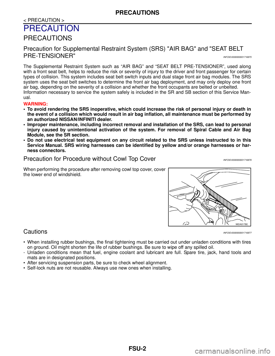
When performing the procedure after removing cowl top cover, cover
the lower end of windshield.
CautionsINFOID:0000000001716877
When installing rubber bushings, the final tightening must be carried out under unladen conditions with tires
on ground. Oil might shorten the life of rubber bushings. Be sure to wipe off any spilled oil.
- Unladen conditions mean that fuel, engine coolant and lubricant are full. Spare tire, jack, hand tools and
mats are in designated positions.
After servicing suspension parts, be sure to check wheel alignment.
Self-lock nuts are not reusable. Always use new ones when installing.
WEIA0178E