2007 NISSAN TIIDA EC Engine Control System
[x] Cancel search: EC Engine Control SystemPage 4323 of 5883

MWI-16
< FUNCTION DIAGNOSIS >
METER SYSTEM
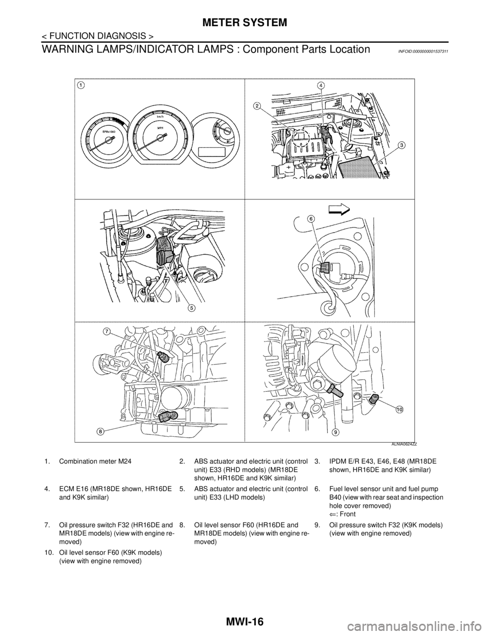
WARNING LAMPS/INDICATOR LAMPS : Component Parts Location
INFOID:0000000001537311
1. Combination meter M24 2. ABS actuator and electric unit (control
unit) E33 (RHD models) (MR18DE
shown, HR16DE and K9K similar)3. IPDM E/R E43, E46, E48 (MR18DE
shown, HR16DE and K9K similar)
4. ECM E16 (MR18DE shown, HR16DE
and K9K similar)5. ABS actuator and electric unit (control
unit) E33 (LHD models)6. Fuel level sensor unit and fuel pump
B40 (view with rear seat and inspection
hole cover removed)
⇐: Front
7. Oil pressure switch F32 (HR16DE and
MR18DE models) (view with engine re-
moved)8. Oil level sensor F60 (HR16DE and
MR18DE models) (view with engine re-
moved)9. Oil pressure switch F32 (K9K models)
(view with engine removed)
10. Oil level sensor F60 (K9K models)
(view with engine removed)
ALNIA0624ZZ
Page 4325 of 5883

MWI-18
< FUNCTION DIAGNOSIS >
METER SYSTEM
The distance to empty indication provides the driver with an estimation of the distance that can be driven
before refueling. The distance to empty is calculated using signals from the fuel level sensor unit (fuel remain-
ing), ECM (fuel consumption) and vehicle speed signals from the ABS actuator and electric unit (control unit).
JOURNY TIME
The travel time since last reset is displayed.
AVERAGE FUEL CONSUMTION
Average fuel consumption indication is calculated using vehicle speed signals from the ABS actuator and elec-
tric unit (control unit) and fuel consumption information from the ECM.
AVERAGE SPEED
The average speed mode can be selected to display the average speed since last reset. The indications are
calculated using vehicle speed signals from the ABS actuator and electric unit (control unit).
OUTSIDE AIR TEMPERATURE
The combination meter indicates the outside air temperature calculated by the temperature signal received
from the ambient sensor.
The indicated temperature is not readily affected by engine heat. It changes only when one of the following
conditions is present.
The temperature detected by the ambient sensor is lower than the indicated temperature
The vehicle speed is greater than 20 km/h (13 MPH)
(This is to prevent the indicated temperature from being affected by engine heat during low-speed driving.)
The ignition switch has been turned to the OFF position for more than 3.5 hours. (The engine is cold.)
When the ambient air temperature falls below 3°C (37°F), the display starts flashing. Approximately 20 sec-
onds later, only “°C” flashes.
NOTE:
On vehicles equipped with auto A/C, the ambient sensor signal is shared with the front air control. The combi-
nation meter is notified of the signal sharing via the auto A/C sense circuit.
Page 4326 of 5883

MWI
METER SYSTEM
MWI-19
< FUNCTION DIAGNOSIS >
C
D
E
F
G
H
I
J
K
L
MB A
O
P
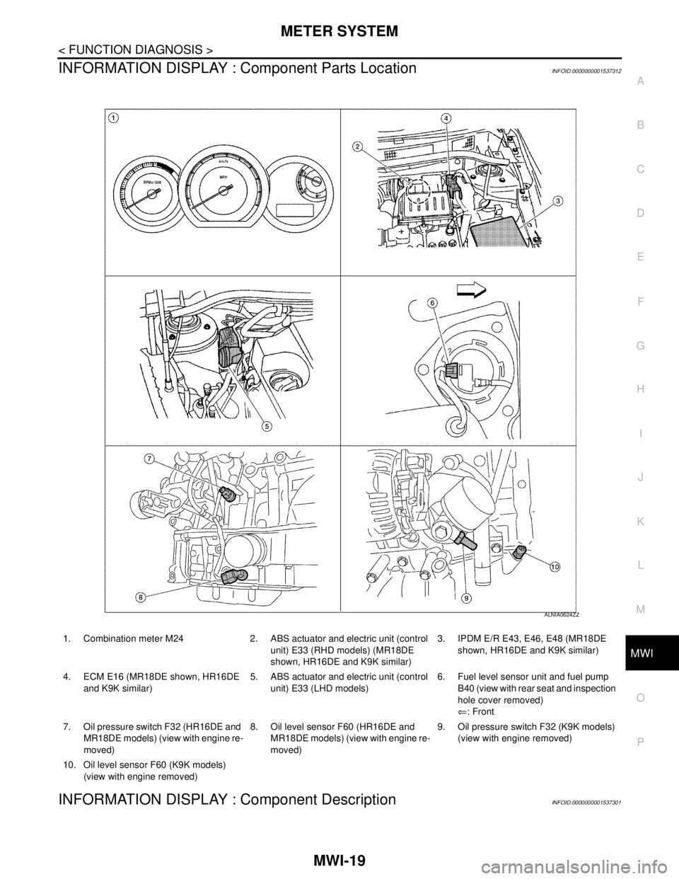
INFORMATION DISPLAY : Component Parts LocationINFOID:0000000001537312
INFORMATION DISPLAY : Component DescriptionINFOID:0000000001537301
1. Combination meter M24 2. ABS actuator and electric unit (control
unit) E33 (RHD models) (MR18DE
shown, HR16DE and K9K similar)3. IPDM E/R E43, E46, E48 (MR18DE
shown, HR16DE and K9K similar)
4. ECM E16 (MR18DE shown, HR16DE
and K9K similar)5. ABS actuator and electric unit (control
unit) E33 (LHD models)6. Fuel level sensor unit and fuel pump
B40 (view with rear seat and inspection
hole cover removed)
⇐: Front
7. Oil pressure switch F32 (HR16DE and
MR18DE models) (view with engine re-
moved)8. Oil level sensor F60 (HR16DE and
MR18DE models) (view with engine re-
moved)9. Oil pressure switch F32 (K9K models)
(view with engine removed)
10. Oil level sensor F60 (K9K models)
(view with engine removed)
ALNIA0624ZZ
Page 4327 of 5883

MWI-20
< FUNCTION DIAGNOSIS >
METER SYSTEM
Unit Description
Combination meter Controls the information display according to the signal received from each unit.
Fuel level sensor unit Refer to MWI-29, "
Description".
ECMTransmits the following signals to the combination meter via CAN communication line.
Engine speed signal Fuel consumption monitor signal
ABS actuator and electric unit
(control unit)Transmits the vehicle speed signal to the combination meter via CAN communication line.
Ambient sensor Refer to MWI-34, "
Description".
Oil level sensor Refer to MWI-32, "
Description".
Page 4363 of 5883

MWI-56
< ECU DIAGNOSIS >
BCM (BODY CONTROL MODULE)
ENGINE RUNEngine stopped OFF
Engine running ON
ENGINE STATUS
NOTE:
Diesel engine models
onlyEngine stopped STOP
While the engine stalls STALL
Engine running RUN
At engine cranking CRA
FA N O N S I GFan switch OFF OFF
Fan switch ON ON
FR FOG SWFront fog lamp switch OFF OFF
Front fog lamp switch ON ON
FR WASHER SWFront washer switch OFF OFF
Front washer switch ON ON
FR WIPER LOWFront wiper switch OFF OFF
Front wiper switch LO ON
FR WIPER HIFront wiper switch OFF OFF
Front wiper switch HI ON
FR WIPER INTFront wiper switch OFF OFF
Front wiper switch INT ON
FR WIPER STOPAny position other than front wiper stop position OFF
Front wiper stop position ON
HAZARD SWWhen hazard switch is not pressed OFF
When hazard switch is pressed ON
LIGHT SW 1STLighting switch OFF OFF
Lighting switch 1st ON
H/L SW POSHeadlamp switch OFF OFF
Headlamp switch 1st ON
HI BEAM SWHigh beam switch OFF OFF
High beam switch HI ON
HOOD SWClose the hood
NOTE:
Vehicles without theft warning system are OFF-fixedOFF
Open the hood ON
H/L WASH SWNOTE:
The item is indicated, but not monitoredOFF
IGN ON SWIgnition switch OFF or ACC OFF
Ignition switch ON ON
IGN SW CANIgnition switch OFF or ACC OFF
Ignition switch ON ON
INT VOLUME Wiper intermittent dial is in a dial position 1 - 7 1 - 7
I-KEY LOCK
1LOCK button of Intelligent Key is not pressed OFF
LOCK button of Intelligent Key is pressed ON
I-KEY UNLOCK
1UNLOCK button of Intelligent Key is not pressed OFF
UNLOCK button of Intelligent Key is pressed ON
KEY SW
2Mechanical key is removed from key cylinder OFF
Mechanical key is inserted to key cylinder ON Monitor Item Condition Value/Status
Page 4364 of 5883

MWI
BCM (BODY CONTROL MODULE)
MWI-57
< ECU DIAGNOSIS >
C
D
E
F
G
H
I
J
K
L
MB A
O
P
1: With Intelligent Key
2: With remote keyless entry system
3: HatchbackKEYLESS LOCK
2LOCK button of key fob is not pressed OFF
LOCK button of key fob is pressed ON
KEYLESS UNLOCK
2UNLOCK button of key fob is not pressed OFF
UNLOCK button of key fob is pressed ON
LIT-SEN FAILLight & rain sensor is in normal condition OK
Light & rain sensor is with internal error NOTOK
OIL PRESS SW Ignition switch OFF or ACC
Engine runningOFF
Ignition switch ON ON
OUT SIDE TEMP
NOTE:
Diesel engine modelsIgnition switch ONApproximately the same as outside
air temperature
PASSING SWOther than lighting switch PASS OFF
Lighting switch PASS ON
PUSH SW
1Return to ignition switch to LOCK position OFF
Press ignition switch ON
REAR DEF SWRear window defogger switch OFF OFF
Rear window defogger switch ON ON
RKE LOCK AND
UNLOCK
2NOTE:
The item is indicated, but not monitoredOFF
ON
RR FOG SWRear fog lamp switch OFF OFF
Rear fog lamp switch ON ON
RR WASHER SW
3Rear washer switch OFF OFF
Rear washer switch ON ON
RR WIPER INT
3Rear wiper switch OFF OFF
Rear wiper switch INT ON
RR WIPER ON
3 Rear wiper switch OFF OFF
Rear wiper switch ON ON
RR WIPER STOP
3Rear wiper stop position OFF
Other than rear wiper stop position ON
TAIL LAMP SWLighting switch OFF OFF
Lighting switch 1ST ON
TRNK OPNR SWWhen back door opener switch is not pressed OFF
When back door opener switch is pressed ON
TURN SIGNAL LTurn signal switch OFF OFF
Turn signal switch LH ON
TURN SIGNAL RTurn signal switch OFF OFF
Turn signal switch RH ON
UNLOCK WITH DRNOTE:
The item is indicated, but not monitoredOFF
ON
VEHICLE SPEED While driving Equivalent to speedometer reading Monitor Item Condition Value/Status
Page 4385 of 5883

MWI-78
< ECU DIAGNOSIS >
IPDM E/R (INTELLIGENT POWER DISTRIBUTION MODULE ENGINE ROOM)
Te r m i n a lWire
colorSignal nameSignal
input/
outputMeasuring condition
Reference value
(Approx.) Ignition
switchOperation or condition
1 R Battery power supply Input OFF — Battery voltage
2 G Battery power supply Input OFF — Battery voltage
3 Y ECM Relay Output —Ignition switch ON or START Battery voltage
Ignition switch OFF or ACC 0V
4 G ECM relay Output —Ignition switch ON or START Battery voltage
Ignition switch OFF or ACC 0V
6GRDaytime light relay
controlInput ON Daytime light system active. Less than battery voltage
Daytime light system inactive. Battery voltage
7 G ECM relay control Input —Ignition switch ON or START 0V
Ignition switch OFF or ACC Battery voltage
8GThrottle control motor
relayOutput —Ignition switch ON or START Battery voltage
Ignition switch OFF or ACC 0V
11 W A/C compressor OutputON or
STARTA/C switch ON or defrost A/C
switchBattery voltage
A/C switch OFF or defrost A/C
switch0V
12 OIgnition switch sup-
plied powerInput —OFF or ACC 0V
ON or START Battery voltage
14BR
(M/T)
R
(A/T)Fuse 49 Output —Ignition switch ON or START Battery voltage
Ignition switch OFF or ACC 0V
15 V Fuse 50 Output —Ignition switch ON or START Battery voltage
Ignition switch OFF or ACC 0V
16 SB Fuse 51 Output —Ignition switch ON or START Battery voltage
Ignition switch OFF or ACC 0V
19 R Starter motor Output START — Battery voltage
20L
(with
A/C)
LG
(with-
out A/
C)Cooling fan relay-1 Output —Conditions correct for cooling
fan low operation.Battery voltage
Conditions not correct for
cooling fan low operation.0V
21 WIgnition switch START
signalInput START — Battery voltage
22 G Battery power supply Input — — Battery voltage
23 L Cooling fan relay-2 Input —Conditions correct for cooling
fan high operationBattery voltage
Conditions not correct for
cooling fan high operation0V
24 Y Cooling fan relay-3 Output —Conditions correct for cooling
fan high operationBattery voltage
Conditions not correct for
cooling fan high operation0V
27 BR
Tail lamp relay (park-
ing lamps)Output — Lighting switch in 2nd position Battery voltage
Page 4415 of 5883

PCS
PCS-1
ELECTRICAL & POWER CONTROL
C
D
E
F
G
H
I
J
K
L B
SECTION PCS
A
O
P N
CONTENTS
POWER CONTROL SYSTEM
IPDM E/R
FUNCTION DIAGNOSIS ...............................
3
RELAY CONTROL SYSTEM ..............................3
System Diagram ........................................................3
System Description ...................................................4
Component Parts Location ........................................5
POWER CONTROL SYSTEM .............................6
System Diagram ........................................................6
System Description ...................................................6
SIGNAL BUFFER SYSTEM ................................7
System Diagram ........................................................7
System Description ...................................................7
POWER CONSUMPTION CONTROL SYS-
TEM .....................................................................
8
System Diagram ........................................................8
System Description ...................................................8
Component Parts Location ........................................9
DIAGNOSIS SYSTEM (IPDM E/R) .....................10
Diagnosis Description .............................................10
CONSULT - III Function (IPDM E/R) .......................13
COMPONENT DIAGNOSIS .........................15
U1000 CAN COMM CIRCUIT .............................15
Description ..............................................................15
DTC Logic ...............................................................15
Diagnosis Procedure ...............................................15
POWER SUPPLY AND GROUND CIRCUIT ......16
Diagnosis Procedure ...............................................16
ECU DIAGNOSIS .........................................17
IPDM E/R (INTELLIGENT POWER DISTRI-
BUTION MODULE ENGINE ROOM) .................
17
Reference Value .....................................................17
Terminal Layout ......................................................19
Physical Values .......................................................19
Wiring Diagram ........................................................23
Fail Safe ..................................................................26
DTC Index ...............................................................28
PRECAUTION ..............................................29
PRECAUTIONS .................................................29
Precaution for Supplemental Restraint System
(SRS) "AIR BAG" and "SEAT BELT PRE-TEN-
SIONER" .................................................................
29
REMOVAL AND INSTALLATION ...............30
IPDM E/R (INTELLIGENT POWER DISTRI-
BUTION MODULE ENGINE ROOM) ................
30
Removal and Installation of IPDM E/R ....................30
POWER DISTRIBUTION SYSTEM
BASIC INSPECTION ...................................
31
DIAGNOSIS AND REPAIR WORKFLOW ........31
Work Flow ................................................................31
FUNCTION DIAGNOSIS ..............................34
POWER DISTRIBUTION SYSTEM ...................34
System Description ..................................................34
Component Parts Location ......................................34
Component Description ..........................................34
DIAGNOSIS SYSTEM (BCM) ...........................35
COMMON ITEM .........................................................35
COMMON ITEM : Diagnosis Description ................35
COMMON ITEM : CONSULT-III Function ...............35
INTELLIGENT KEY ....................................................35
INTELLIGENT KEY : CONSULT-III Function
(BCM - INTELLIGENT KEY) ....................................
35
COMPONENT DIAGNOSIS .........................36