2007 NISSAN TIIDA EC Engine Control System
[x] Cancel search: EC Engine Control SystemPage 4250 of 5883
MA-10
< ON-VEHICLE MAINTENANCE >
PERIODIC MAINTENANCE
NOTE:
Maintenance items with “ ” should be performed more frequently according to “Maintenance Under Severe Driving Con-
ditions”.
(1) Inspect once per year.
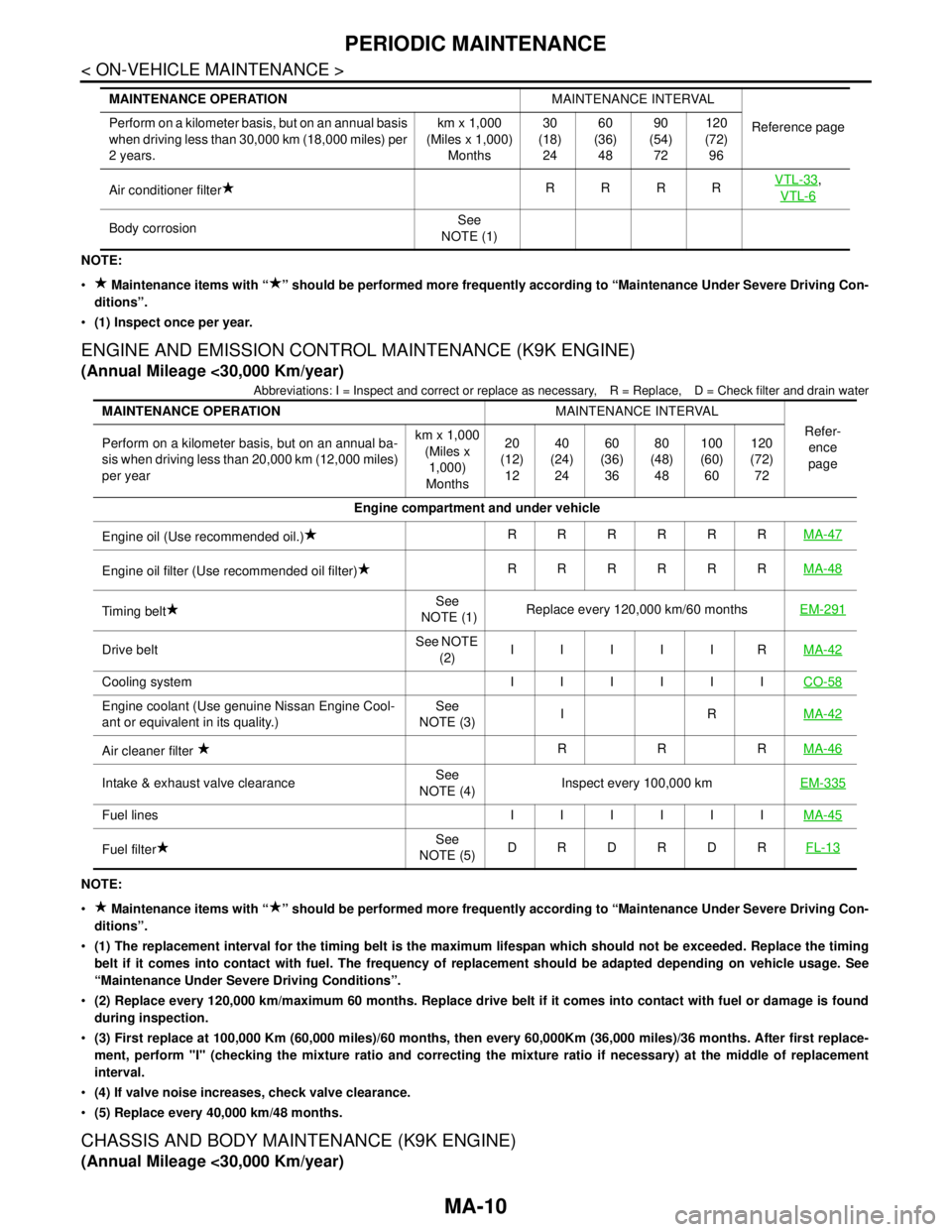
ENGINE AND EMISSION CONTROL MAINTENANCE (K9K ENGINE)
(Annual Mileage <30,000 Km/year)
Abbreviations: I = Inspect and correct or replace as necessary, R = Replace, D = Check filter and drain water
NOTE:
Maintenance items with “ ” should be performed more frequently according to “Maintenance Under Severe Driving Con-
ditions”.
(1) The replacement interval for the timing belt is the maximum lifespan which should not be exceeded. Replace the timing
belt if it comes into contact with fuel. The frequency of replacement should be adapted depending on vehicle usage. See
“Maintenance Under Severe Driving Conditions”.
(2) Replace every 120,000 km/maximum 60 months. Replace drive belt if it comes into contact with fuel or damage is found
during inspection.
(3) First replace at 100,000 Km (60,000 miles)/60 months, then every 60,000Km (36,000 miles)/36 months. After first replace-
ment, perform "I" (checking the mixture ratio and correcting the mixture ratio if necessary) at the middle of replacement
interval.
(4) If valve noise increases, check valve clearance.
(5) Replace every 40,000 km/48 months.
CHASSIS AND BODY MAINTENANCE (K9K ENGINE)
(Annual Mileage <30,000 Km/year)
Air conditioner filterRRRRVTL-33,
VTL-6
Body corrosionSee
NOTE (1) MAINTENANCE OPERATIONMAINTENANCE INTERVAL
Reference page Perform on a kilometer basis, but on an annual basis
when driving less than 30,000 km (18,000 miles) per
2 years.km x 1,000
(Miles x 1,000)
Months30
(18)
2460
(36)
4890
(54)
72120
(72)
96
MAINTENANCE OPERATIONMAINTENANCE INTERVAL
Refer-
ence
page Perform on a kilometer basis, but on an annual ba-
sis when driving less than 20,000 km (12,000 miles)
per yearkm x 1,000
(Miles x
1,000)
Months20
(12)
1240
(24)
2460
(36)
3680
(48)
48100
(60)
60120
(72)
72
Engine compartment and under vehicle
Engine oil (Use recommended oil.)RRRRRRMA-47
Engine oil filter (Use recommended oil filter)RRRRRRMA-48
Timing beltSee
NOTE (1)Replace every 120,000 km/60 monthsEM-291
Drive beltSee NOTE
(2)IIIIIRMA-42
Cooling system IIIIIICO-58
Engine coolant (Use genuine Nissan Engine Cool-
ant or equivalent in its quality.)See
NOTE (3)IRMA-42
Air cleaner filter RRRMA-46
Intake & exhaust valve clearanceSee
NOTE (4)Inspect every 100,000 kmEM-335
Fuel lines IIIIIIMA-45
Fuel filterSee
NOTE (5)DRDRDRFL-13
Page 4252 of 5883
MA-12
< ON-VEHICLE MAINTENANCE >
PERIODIC MAINTENANCE
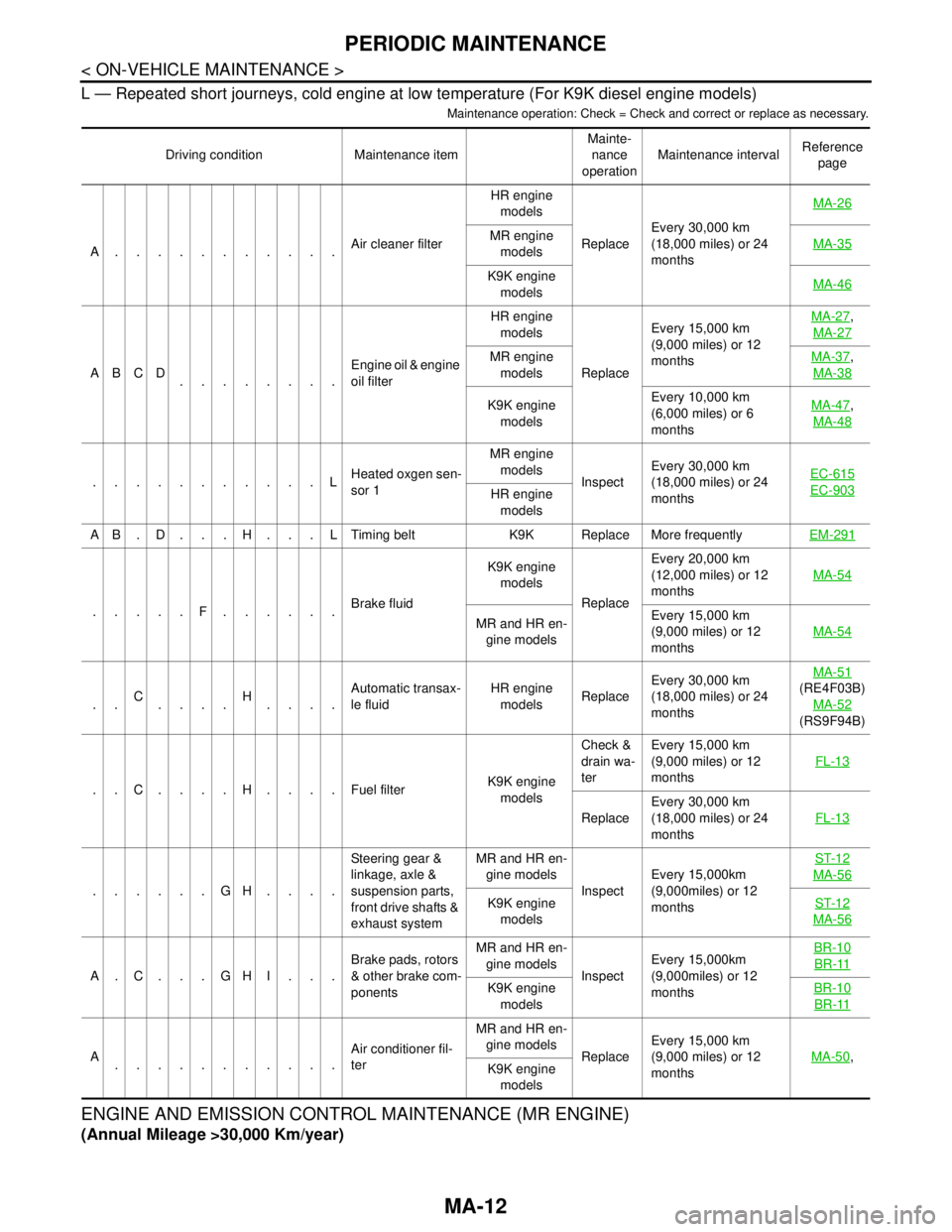
L — Repeated short journeys, cold engine at low temperature (For K9K diesel engine models)
Maintenance operation: Check = Check and correct or replace as necessary.
ENGINE AND EMISSION CONTROL MAINTENANCE (MR ENGINE)
(Annual Mileage >30,000 Km/year)
Driving condition Maintenance itemMainte-
nance
operationMaintenance intervalReference
page
A...........Air cleaner filterHR engine
models
ReplaceEvery 30,000 km
(18,000 miles) or 24
monthsMA-26
MR engine
modelsMA-35
K9K engine
modelsMA-46
ABCD
........Engine oil & engine
oil filter HR engine
models
ReplaceEvery 15,000 km
(9,000 miles) or 12
monthsMA-27
,
MA-27
MR engine
modelsMA-37,
MA-38
K9K engine
modelsEvery 10,000 km
(6,000 miles) or 6
monthsMA-47,
MA-48
...........LHeated oxgen sen-
sor 1MR engine
models
InspectEvery 30,000 km
(18,000 miles) or 24
monthsEC-615EC-903HR engine
models
A B . D . . . H . . . L Timing belt K9K Replace More frequentlyEM-291
.....F......Brake fluidK9K engine
models
ReplaceEvery 20,000 km
(12,000 miles) or 12
monthsMA-54MR and HR en-
gine modelsEvery 15,000 km
(9,000 miles) or 12
monthsMA-54
..C
....H
....Automatic transax-
le fluidHR engine
modelsReplaceEvery 30,000 km
(18,000 miles) or 24
monthsMA-51
(RE4F03B)
MA-52
(RS9F94B)
..C....H....Fuel filter K9K engine
modelsCheck &
drain wa-
terEvery 15,000 km
(9,000 miles) or 12
monthsFL-13
ReplaceEvery 30,000 km
(18,000 miles) or 24
monthsFL-13
......GH....Steering gear &
linkage, axle &
suspension parts,
front drive shafts &
exhaust systemMR and HR en-
gine models
InspectEvery 15,000km
(9,000miles) or 12
monthsST-12
MA-56
K9K engine
modelsST-12
MA-56
A.C...GHI...Brake pads, rotors
& other brake com-
ponentsMR and HR en-
gine models
InspectEvery 15,000km
(9,000miles) or 12
monthsBR-10BR-11
K9K engine
modelsBR-10
BR-11
A
...........Air conditioner fil-
terMR and HR en-
gine models
ReplaceEvery 15,000 km
(9,000 miles) or 12
monthsMA-50,
K9K engine
models
Page 4254 of 5883
MA-14
< ON-VEHICLE MAINTENANCE >
PERIODIC MAINTENANCE
NOTE:
(1) Inspect once per year.
Maintenance items with “ ” should be performed more frequently according to “Maintenance Under Severe Driving Con-
ditions”.
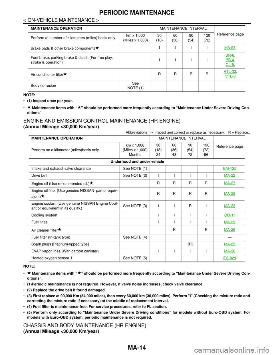
ENGINE AND EMISSION CONTROL MAINTENANCE (HR ENGINE)
(Annual Mileage >30,000 Km/year)
Abbreviations: I = Inspect and correct or replace as necessary, R = Replace,.
NOTE:
Maintenance items with “ ” should be performed more frequently according to “Maintenance Under Severe Driving Con-
ditions”.
(1)Periodic maintenance is not required. However, if valve noise increases, check valve clearance.
(2) Replace the drive belt if found damaged.
(3) First replace at 90,000 Km (54,000 miles), then every 60,000 km (36,000 miles). Perform "I" (Checking the mixture ratio and
correcting the mixture ratio if necessary) at the middle of replacement interval.
(4) Fuel filter is maintenance-free. For service procedures, refer to FL section.
(5) Perform only according to “Maintenance Under Severe Driving conditions” for models without Euro-OBD system. For
models with Euro-OBD system, periodic maintenance is not required.
CHASSIS AND BODY MAINTENANCE (HR ENGINE)
(Annual Mileage <30,000 Km/year)
Brake pads & other brake componentsIIIIMA-55,
Foot brake, parking brake & clutch (For free play,
stroke & operation)IIIIBR-6
,
PB-4
,
CL-5
,
Air conditioner filterRRRRVTL-33
,
VTL-6
Body corrosionSee
NOTE (1) MAINTENANCE OPERATIONMAINTENANCE INTERVAL
Reference page
Perform at number of kilometers (miles) basis only.km x 1,000
(Miles x 1,000)30
(18)60
(36)90
(54)120
(72)
MAINTENANCE OPERATIONMAINTENANCE INTERVAL
Reference page
Perform on a kilometer (miles)basis only.km x 1,000
(Miles x 1,000)
Months30
(18)
2460
(36)
4890
(54)
72120
(72)
96
Underhood and under vehicle
Intake and exhaust valve clearance See NOTE (1)EM-125
Drive belt See NOTE (2)IIIIMA-22
Engine oil (Use recommended oil.)RRRRMA-27
Engine oil filter (Use genuine NISSAN part or equiv-
alent)RRRRMA-28
Engine coolant (Use genuine NISSAN Engine Cool-
ant or equivalent in its quality.)See NOTE (3) I I R IMA-23
Cooling system IIIICO-11
Fuel lines IIIIMA-25
Air cleaner filterRRMA-26
Fuel filter (In-tank type) See NOTE (4) —
Spark plugs [Platinum-tipped type] [R]MA-29
EVAP vapor lines (With carbon canister) IIIIMA-30
Heated oxygen sensor 1 See NOTE (5)EC-829
Page 4255 of 5883
PERIODIC MAINTENANCE
MA-15
< ON-VEHICLE MAINTENANCE >
C
D
E
F
G
H
I
J
K
L
MB
MAN
OA
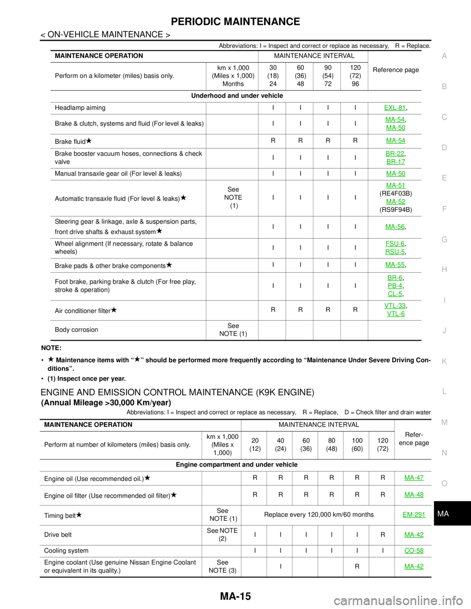
Abbreviations: I = Inspect and correct or replace as necessary, R = Replace.
NOTE:
Maintenance items with “ ” should be performed more frequently according to “Maintenance Under Severe Driving Con-
ditions”.
(1) Inspect once per year.
ENGINE AND EMISSION CONTROL MAINTENANCE (K9K ENGINE)
(Annual Mileage >30,000 Km/year)
Abbreviations: I = Inspect and correct or replace as necessary, R = Replace, D = Check filter and drain water
MAINTENANCE OPERATIONMAINTENANCE INTERVAL
Reference page
Perform on a kilometer (miles) basis only.km x 1,000
(Miles x 1,000)
Months30
(18)
2460
(36)
4890
(54)
72120
(72)
96
Underhood and under vehicle
Headlamp aiming IIIIEXL-81
,
Brake & clutch, systems and fluid (For level & leaks) IIIIMA-54
,
MA-50
Brake fluidRRRRMA-54
Brake booster vacuum hoses, connections & check
valveIIIIBR-22,
BR-17
Manual transaxle gear oil (For level & leaks) IIIIMA-50
Automatic transaxle fluid (For level & leaks)See
NOTE
(1)IIIIMA-51(RE4F03B)
MA-52
(RS9F94B)
Steering gear & linkage, axle & suspension parts,
front drive shafts & exhaust systemIIIIMA-56
,
Wheel alignment (If necessary, rotate & balance
wheels)IIIIFSU-6
,
RSU-5
,
Brake pads & other brake componentsIIIIMA-55
,
Foot brake, parking brake & clutch (For free play,
stroke & operation)IIIIBR-6
,
PB-4
,
CL-5
,
Air conditioner filterRRRRVTL-33
,
VTL-6
Body corrosionSee
NOTE (1)
MAINTENANCE OPERATIONMAINTENANCE INTERVAL
Refer-
ence page
Perform at number of kilometers (miles) basis only.km x 1,000
(Miles x
1,000)20
(12)40
(24)60
(36)80
(48)100
(60)120
(72)
Engine compartment and under vehicle
Engine oil (Use recommended oil.)RRRRRRMA-47
Engine oil filter (Use recommended oil filter)RRRRRRMA-48
Timing beltSee
NOTE (1)Replace every 120,000 km/60 monthsEM-291
Drive beltSee NOTE
(2)IIIIIRMA-42
Cooling system IIIIIICO-58
Engine coolant (Use genuine Nissan Engine Coolant
or equivalent in its quality.)See
NOTE (3)IRMA-42
Page 4265 of 5883
ENGINE MAINTENANCE (HR16DE)
MA-25
< ON-VEHICLE MAINTENANCE >
C
D
E
F
G
H
I
J
K
L
MB
MAN
OA
11. Refill reservoir tank to “MAX” level line with engine coolant.
12. Repeat steps 6 through 11 two or more times with radiator cap installed until engine coolant level no
longer drops.
13. Check cooling system for leaks with engine running.
14. Warm up engine, and check for sound of engine coolant flow while running engine from idle up to 3,000
rpm with heater temperature controller set at several position between “COOL” and “WARM”.
Sound may be noticeable at heater unit.
15. Repeat step 14 three times.
16. If sound is heard, bleed air from cooling system by repeating steps 6 through 11 until engine coolant level
no longer drops.
FLUSHING COOLING SYSTEM
1. Install reservoir tank if removed.
2. Install radiator drain plug.
If water drain plug on cylinder block is removed, close and tighten it. Refer to EM-100, "
Exploded
View".
CAUTION:
Be sure to clean radiator drain plug and install with new O-ring. Refer to CO-16, "
Component".
3. Fill radiator and reservoir tank with water and reinstall radiator cap.
4. Run engine and warm it up to normal operating temperature.
5. Rev engine two or three times under no-load.
6. Stop engine and wait until it cools down.
7. Drain water from the cooling system. Refer to CO-11, "
Changing Engine Coolant".
8. Repeat steps 1 through 7 until clear water begins to drain from radiator.
RADIATOR
RADIATOR : Checking RadiatorINFOID:0000000001730858
Check radiator for mud or clogging. If necessary, clean radiator as follows.
Be careful not to bend or damage radiator fins.
When radiator is cleaned without removal, remove all surrounding parts such as cooling fan, radiator shroud
and horns. Then tape harness and connectors to prevent water from entering.
1. Apply water by hose to the back side of the radiator core vertically downward.
2. Apply water again to all radiator core surface once per minute.
3. Stop washing if any stains no longer flow out from radiator.
4. Blow air into the back side of radiator core vertically downward.
Use compressed air lower than 490 kPa (4.9 bar, 5 kg/cm
2, 71 psi) and keep distance more than 30 cm
(11.8 in).
5. Blow air again into all the radiator core surfaces once per minute until no water sprays out.
FUEL LINES
FUEL LINES : InspectionINFOID:0000000001277610
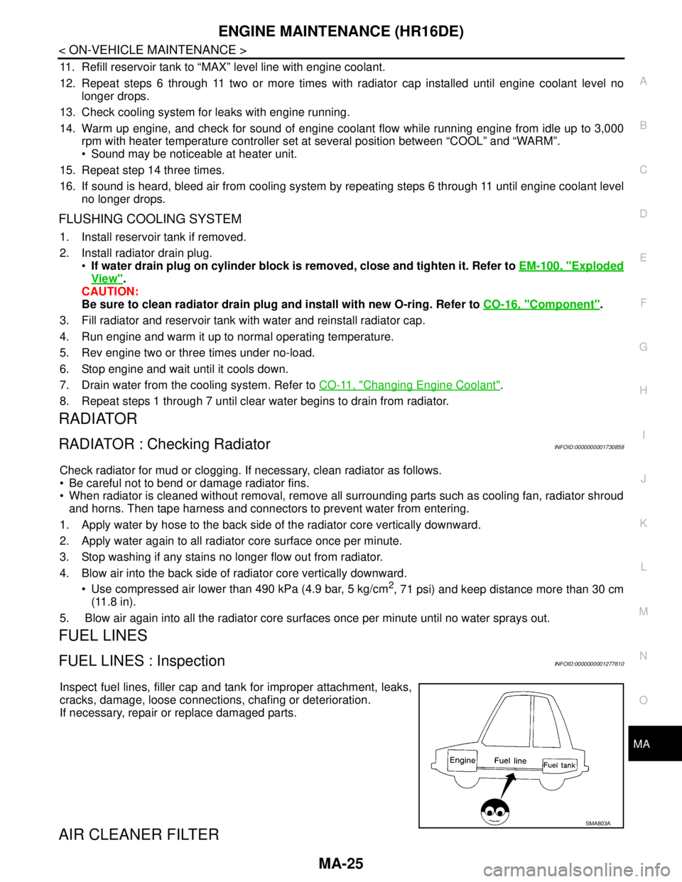
Inspect fuel lines, filler cap and tank for improper attachment, leaks,
cracks, damage, loose connections, chafing or deterioration.
If necessary, repair or replace damaged parts.
AIR CLEANER FILTER
SMA803A
Page 4273 of 5883

ENGINE MAINTENANCE (MR18DE)
MA-33
< ON-VEHICLE MAINTENANCE >
C
D
E
F
G
H
I
J
K
L
MB
MAN
OA
6. Fill radiator and reservoir tank to specified level.
Pour engine coolant through engine coolant filler neck
slowly of less than 2 (2 1/8 US qt, 1-3/4 lmp qt) a minute
to allow air in system to escape.
Use NISSAN Genuine Engine Coolant or equivalent mixed
with water (distilled or demineralized). Fill cooling system
to specification. Refer to MA-19, "
Fluids and Lubricants".
When engine coolant overflows disconnected heater hose,
connect heater hose, and continue filling the engine coolant, if
heater hose is disconnected.
7. Install radiator cap.
8. Install air duct assembly. Refer to EM-154, "
Component".
9. Warm up until opening thermostat. Standard for warming-up time is approximately 10 minutes at 3,000
rpm.
Make sure thermostat opening condition by touching radiator hose (lower) to see a flow of warm water.
CAUTION:
Watch water temperature gauge so as not to overheat the engine.
10. Stop engine and cool down to less than approximately 50°C (122°F).
Cool down using fan to reduce the time.
If necessary, refill radiator up to filler neck with engine coolant.
11. Refill reservoir tank to “MAX” level line with engine coolant.
12. Repeat steps 6 through 11 two or more times with radiator cap installed until engine coolant level no
longer drops.
13. Check cooling system for leaks with engine running.
14. Warm up engine, and check for sound of engine coolant flow while running engine from idle up to 3,000
rpm with heater temperature controller set at several position between “COOL” and “WARM”.
Sound may be noticeable at heater unit.
15. Repeat step 14 three times.
16. If sound is heard, bleed air from cooling system by repeating steps 6 through 11 until engine coolant level
no longer drops.
FLUSHING COOLING SYSTEM
1. Install reservoir tank if removed.
2. Install radiator drain plug.
If water drain plug on cylinder block is removed, close and tighten it. Refer to EM-211, "
Compo-
nent".
CAUTION:
Be sure to clean radiator drain plug and install with new O-ring. Refer to CO-40, "
Component".
3. Fill radiator and reservoir tank with water and reinstall radiator cap.
4. Run engine and warm it up to normal operating temperature.
5. Rev engine two or three times under no-load.
6. Stop engine and wait until it cools down.
7. Drain water from the cooling system. Refer to CO-35, "
Changing Engine Coolant".
8. Repeat steps 1 through 7 until clear water begins to drain from radiator.
RADIATOR
SMA182B
Page 4308 of 5883

MWI
MWI-1
DRIVER INFORMATION & MULTIMEDIA
C
D
E
F
G
H
I
J
K
L
MB
SECTION MWI
A
O
P
CONTENTS
METER, WARNING LAMP & INDICATOR
BASIC INSPECTION ....................................3
DIAGNOSIS AND REPAIR WORKFLOW ..........3
Work Flow .................................................................3
FUNCTION DIAGNOSIS ...............................4
METER SYSTEM .................................................4
METER SYSTEM .........................................................4
METER SYSTEM : System Diagram ........................4
METER SYSTEM : System Description ....................4
METER SYSTEM : Arrangement of Combination
Meter .........................................................................
5
METER SYSTEM : Component Parts Location ........6
METER SYSTEM : Component Description .............7
SPEEDOMETER ..........................................................7
SPEEDOMETER : System Diagram .........................7
SPEEDOMETER : System Description .....................7
SPEEDOMETER : Component Parts Location .........8
SPEEDOMETER : Component Description ..............9
TACHOMETER ............................................................9
TACHOMETER : System Diagram ...........................9
TACHOMETER : System Description .......................9
TACHOMETER : Component Parts Location .........10
TACHOMETER : Component Description ..............11
FUEL GAUGE ............................................................11
FUEL GAUGE : System Diagram ...........................11
FUEL GAUGE : System Description .......................11
FUEL GAUGE : Component Parts Location ...........12
FUEL GAUGE : Component Description ................13
ODO/TRIP METER ....................................................13
ODO/TRIP METER : System Diagram ....................13
ODO/TRIP METER : System Description ...............13
ODO/TRIP METER : Component Parts Location ....14
ODO/TRIP METER : Component Description .........15
WARNING LAMPS/INDICATOR LAMPS ..................15
WARNING LAMPS/INDICATOR LAMPS : System
Diagram ...................................................................
15
WARNING LAMPS/INDICATOR LAMPS : System
Description ...............................................................
15
WARNING LAMPS/INDICATOR LAMPS : Com-
ponent Parts Location ..............................................
16
WARNING LAMPS/INDICATOR LAMPS : Com-
ponent Description ...................................................
17
INFORMATION DISPLAY ..........................................17
INFORMATION DISPLAY : System Diagram ..........17
INFORMATION DISPLAY : System Description .....17
INFORMATION DISPLAY : Component Parts Lo-
cation .......................................................................
19
INFORMATION DISPLAY : Component Descrip-
tion ...........................................................................
19
DIAGNOSIS SYSTEM (METER) .......................21
Diagnosis Description ..............................................21
CONSULT-III Function (METER/M&A) ....................22
COMPONENT DIAGNOSIS .........................24
DTC U1000 CAN COMMUNICATION ...............24
DTC Logic ................................................................24
Diagnosis Procedure ..............................................24
DTC B2205 VEHICLE SPEED CIRCUIT ..........25
Description ...............................................................25
DTC Logic ................................................................25
Diagnosis Procedure ..............................................25
POWER SUPPLY AND GROUND CIRCUIT ....26
COMBINATION METER ............................................26
COMBINATION METER : Diagnosis Procedure .....26
BCM (BODY CONTROL MODULE) ..........................26
BCM (BODY CONTROL MODULE) : Diagnosis
Procedure ................................................................
26
IPDM E/R (INTELLIGENT POWER DISTRIBU-
TION MODULE ENGINE ROOM) ..........................
Page 4309 of 5883

MWI-2
IPDM E/R (INTELLIGENT POWER DISTRIBU-
TION MODULE ENGINE ROOM) : Diagnosis Pro-
cedure .....................................................................
27
FUEL LEVEL SENSOR SIGNAL CIRCUIT .......29
Description ..............................................................29
Component Function Check ...................................29
Diagnosis Procedure .............................................29
Component Inspection ............................................30
OIL PRESSURE SWITCH SIGNAL CIRCUIT ...31
Description ..............................................................31
Component Function Check ...................................31
Diagnosis Procedure ..............................................31
Component Inspection ............................................31
OIL LEVEL SENSOR SIGNAL CIRCUIT ..........32
Description ..............................................................32
Diagnosis Procedure (With Diesel) .........................32
Diagnosis Procedure (Without Diesel) ....................32
Component Inspection (With Diesel) ......................32
Component Inspection (Without Diesel) .................33
AMBIENT SENSOR SIGNAL CIRCUIT .............34
Description ..............................................................34
Diagnosis Procedure ..............................................34
Component Inspection ............................................35
ECU DIAGNOSIS ........................................36
COMBINATION METER ....................................36
Reference Value .....................................................36
Wiring Diagram .......................................................39
Fail Safe .................................................................53
DTC Index ..............................................................54
BCM (BODY CONTROL MODULE) ..................55
Reference Value .....................................................55
Terminal Layout ......................................................58
Physical Values ......................................................58
Wiring Diagram .......................................................70
DTC Inspection Priority Chart ..............................73
DTC Index ..............................................................74
IPDM E/R (INTELLIGENT POWER DISTRI-
BUTION MODULE ENGINE ROOM) .................
75
Reference Value .....................................................75
Terminal Layout ......................................................77
Physical Values ......................................................77
Wiring Diagram .......................................................81
Fail Safe .................................................................84
DTC Index ..............................................................86
SYMPTOM DIAGNOSIS ............................87
THE FUEL GAUGE POINTER DOES NOT
MOVE .................................................................
87
Description ..............................................................87
Diagnosis Procedure ...............................................87
THE FUEL GAUGE POINTER DOES NOT
MOVE TO "F" WHEN REFUELING ..................
88
Description ..............................................................88
Diagnosis Procedure ...............................................88
THE OIL PRESSURE WARNING LAMP
DOES NOT TURN ON .......................................
89
Description ..............................................................89
Diagnosis Procedure ...............................................89
THE OIL PRESSURE WARNING LAMP
DOES NOT TURN OFF .....................................
90
Description ..............................................................90
Diagnosis Procedure ...............................................90
THE AMBIENT TEMPERATURE DISPLAY IS
INCORRECT ......................................................
91
Description ..............................................................91
Diagnosis Procedure ...............................................91
NORMAL OPERATING CONDITION ................92
INFORMATION DISPLAY .........................................92
INFORMATION DISPLAY : Description ..................92
PRECAUTION ............................................93
PRECAUTIONS .................................................93
Supplemental Restraint System (SRS) "AIR BAG"
and "SEAT BELT PRE-TENSIONER" ....................
93
ON-VEHICLE REPAIR ...............................94
COMBINATION METER ....................................94
Removal and Installation .........................................94
DISASSEMBLY AND ASSEMBLY ............97
COMBINATION METER ....................................97
Disassembly and Assembly ....................................97