2007 NISSAN TIIDA alignment
[x] Cancel search: alignmentPage 3184 of 5883
FSU-8
< ON-VEHICLE MAINTENANCE >
FRONT SUSPENSION ASSEMBLY
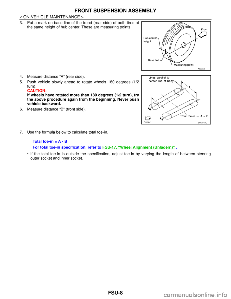
3. Put a mark on base line of the tread (rear side) of both tires at
the same height of hub center. These are measuring points.
4. Measure distance “A” (rear side).
5. Push vehicle slowly ahead to rotate wheels 180 degrees (1/2
turn).
CAUTION:
If wheels have rotated more than 180 degrees (1/2 turn), try
the above procedure again from the beginning. Never push
vehicle backward.
6. Measure distance “B” (front side).
7. Use the formula below to calculate total toe-in.
If the total toe-in is outside the specification, adjust toe-in by varying the length of between steering
outer socket and inner socket.
AFA050
SFA234AC
Total toe-in = A - B
For total toe-in specification, refer to FSU-17, "
Wheel Alignment (Unladen*)" .
Page 3187 of 5883
FRONT SUSPENSION ASSEMBLY
FSU-11
< REMOVAL AND INSTALLATION >
C
D
F
G
H
I
J
K
L
MA
B
FSU
N
O
P
REMOVAL AND INSTALLATION
FRONT SUSPENSION ASSEMBLY
Removal and InstallationINFOID:0000000001716901
REMOVAL
1. Separate intermediate shaft from steering gear pinion shaft. Refer to ST-9, "Removal and Installation".
2. Remove front tires from vehicle using a power tool.
3. Remove wheel sensor from steering knuckle. Refer to BRC-182, "
Removal and Installation".
CAUTION:
Do not pull on wheel sensor harness.
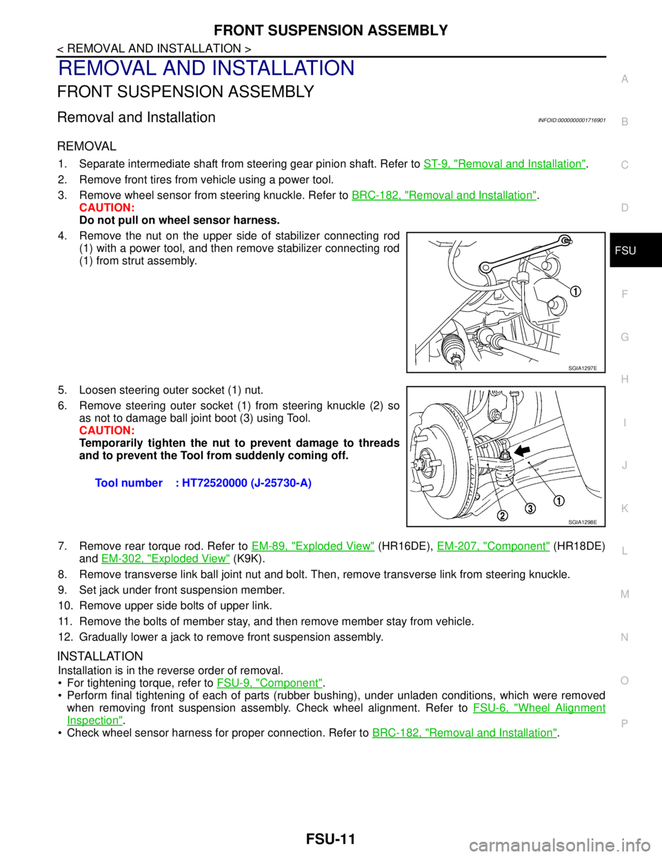
4. Remove the nut on the upper side of stabilizer connecting rod
(1) with a power tool, and then remove stabilizer connecting rod
(1) from strut assembly.
5. Loosen steering outer socket (1) nut.
6. Remove steering outer socket (1) from steering knuckle (2) so
as not to damage ball joint boot (3) using Tool.
CAUTION:
Temporarily tighten the nut to prevent damage to threads
and to prevent the Tool from suddenly coming off.
7. Remove rear torque rod. Refer to EM-89, "
Exploded View" (HR16DE), EM-207, "Component" (HR18DE)
and EM-302, "
Exploded View" (K9K).
8. Remove transverse link ball joint nut and bolt. Then, remove transverse link from steering knuckle.
9. Set jack under front suspension member.
10. Remove upper side bolts of upper link.
11. Remove the bolts of member stay, and then remove member stay from vehicle.
12. Gradually lower a jack to remove front suspension assembly.
INSTALLATION
Installation is in the reverse order of removal.
For tightening torque, refer to FSU-9, "
Component".
Perform final tightening of each of parts (rubber bushing), under unladen conditions, which were removed
when removing front suspension assembly. Check wheel alignment. Refer to FSU-6, "
Wheel Alignment
Inspection".
Check wheel sensor harness for proper connection. Refer to BRC-182, "
Removal and Installation".
SGIA1297E
Tool number : HT72520000 (J-25730-A)
SGIA1298E
Page 3188 of 5883
FSU-12
< REMOVAL AND INSTALLATION >
COIL SPRING AND STRUT
COIL SPRING AND STRUT
Removal and InstallationINFOID:0000000001716888
REMOVAL
1. Remove cowl top panel. Refer to EXT-20, "Removal and Installation" .
2. Remove front tires using power tool.
3. Remove harness of wheel sensor from strut assembly. Refer to BRC-182, "
Removal and Installation" .
CAUTION:
Do not pull on wheel sensor harness.
4. Remove brake hose lock plate. Refer to BR-14, "
Front Brake Tube and Hose" .
5. Remove the nut on the upper side of stabilizer connecting rod using power tool, and then remove stabi-
lizer connecting rod from strut assembly.
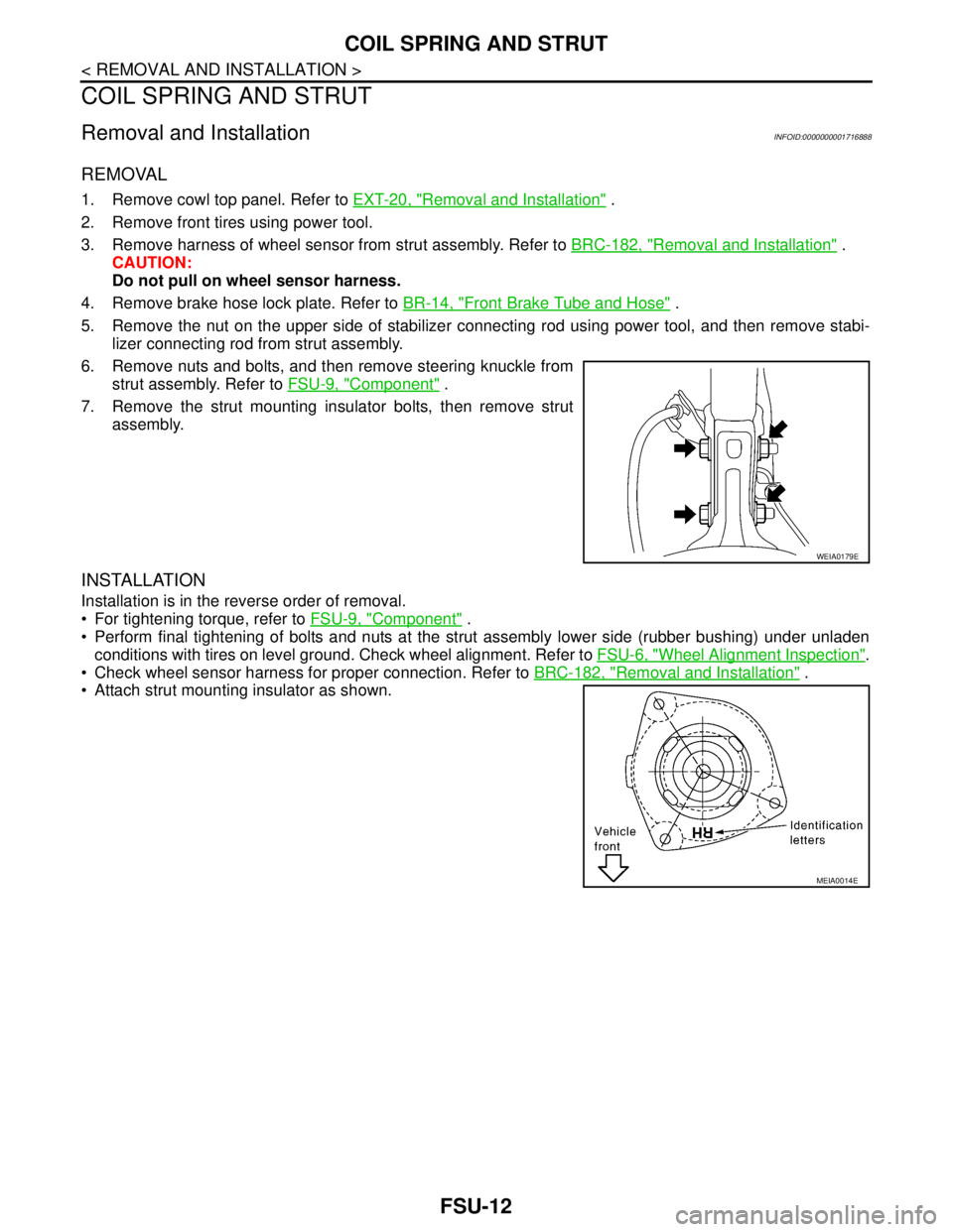
6. Remove nuts and bolts, and then remove steering knuckle from
strut assembly. Refer to FSU-9, "
Component" .
7. Remove the strut mounting insulator bolts, then remove strut
assembly.
INSTALLATION
Installation is in the reverse order of removal.
For tightening torque, refer to FSU-9, "
Component" .
Perform final tightening of bolts and nuts at the strut assembly lower side (rubber bushing) under unladen
conditions with tires on level ground. Check wheel alignment. Refer to FSU-6, "
Wheel Alignment Inspection".
Check wheel sensor harness for proper connection. Refer to BRC-182, "
Removal and Installation" .
Attach strut mounting insulator as shown.
WEIA0179E
MEIA0014E
Page 3189 of 5883
TRANSVERSE LINK
FSU-13
< REMOVAL AND INSTALLATION >
C
D
F
G
H
I
J
K
L
MA
B
FSU
N
O
P
TRANSVERSE LINK
Removal and InstallationINFOID:0000000001716885
REMOVAL
1. Remove front tires using power tool.
2. Remove transverse link ball joint nut and bolt. Then, remove transverse link from steering knuckle.
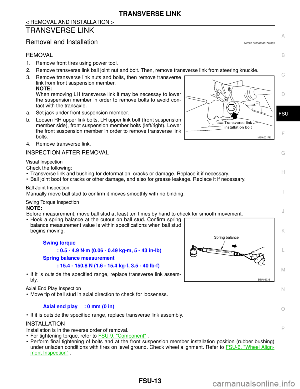
3. Remove transverse link nuts and bolts, then remove transverse
link from front suspension member.
NOTE:
When removing LH transverse link it may be necessay to lower
the suspension member in order to remove bolts to avoid con-
tact with the transaxle.
a. Set jack under front suspension member.
b. Loosen RH upper link bolts, LH upper link bolt (front suspension
member side), front suspension member bolts (left/right). Lower
the front suspension member in order to remove transverse link
bolts.
4. Remove transverse link.
INSPECTION AFTER REMOVAL
Visual Inspection
Check the following:
Transverse link and bushing for deformation, cracks or damage. Replace it if necessary.
Ball joint boot for cracks or other damage, and also for grease leakage. Replace it if necessary.
Ball Joint Inspection
Manually move ball stud to confirm it moves smoothly with no binding.
Swing Torque Inspection
NOTE:
Before measurement, move ball stud at least ten times by hand to check for smooth movement.
Hook a spring balance at the cutout on ball stud. Confirm spring
balance measurement value is within specifications when ball stud
begins moving.
If it is outside the specified range, replace transverse link assem-
bly.
Axial End Play Inspection
Move tip of ball stud in axial direction to check for looseness.
If it is outside the specified range, replace transverse link assembly.
INSTALLATION
Installation is in the reverse order of removal.
For tightening torque, refer to FSU-9, "
Component" .
Perform final tightening of bolts and at the front suspension member installation position (rubber bushing)
under unladen conditions with tires on level ground. Check wheel alignment. Refer to FSU-6, "
Wheel Align-
ment Inspection" .
MEIA0017E
Swing torque
: 0.5 - 4.9 N·m (0.06 - 0.49 kg-m, 5 - 43 in-lb)
Spring balance measurement
: 15.4 - 150.8 N (1.6 - 15.4 kg-f, 3.5 - 40 lb-f)
SEIA0523E
Axial end play : 0 mm (0 in)
Page 3193 of 5883
SERVICE DATA AND SPECIFICATIONS (SDS)
FSU-17
< SERVICE DATA AND SPECIFICATIONS (SDS)
C
D
F
G
H
I
J
K
L
MA
B
FSU
N
O
P
SERVICE DATA AND SPECIFICATIONS (SDS)
SERVICE DATA AND SPECIFICATIONS (SDS)
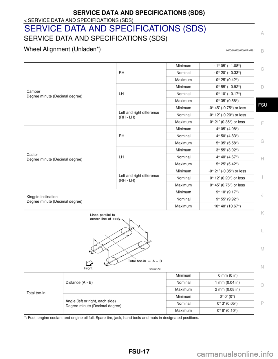
Wheel Alignment (Unladen*)INFOID:0000000001716881
*: Fuel, engine coolant and engine oil full. Spare tire, jack, hand tools and mats in designated positions.Camber
Degree minute (Decimal degree)RHMinimum - 1° 05′ (- 1.08°)
Nominal - 0° 20′ (- 0.33°)
Maximum 0° 25′ (0.42°)
LHMinimum - 0° 55′ (- 0.92°)
Nominal - 0° 10′ (- 0.17°)
Maximum 0° 35′ (0.58°)
Left and right difference
(RH - LH)Minimum -0° 45′ (-0.75°) or less
Nominal -0° 12′ (-0.20°) or less
Maximum 0° 21′ (0.35°) or less
Caster
Degree minute (Decimal degree)RHMinimum 4° 05′ (4.08°)
Nominal 4° 50′ (4.83°)
Maximum 5° 35′ (5.58°)
LHMinimum 3° 55′ (3.92°
)
Nominal 4° 40′ (4.67°)
Maximum 5° 25′ (5.42°)
Left and right difference
(RH - LH)Minimum -0° 21′ (-0.35°) or less
Nominal 0° 12′ (0.20°) or less
Maximum 0° 45′ (0.75°) or less
Kingpin inclination
Degree minute (Decimal degree)Minimum 9° 10′ (9.17°)
Nominal 9° 55′ (9.92°)
Maximum 10° 40′ (10.67°)
Total toe-inDistance (A - B)Minimum 0 mm (0 in)
Nominal 1 mm (0.04 in)
Maximum 2 mm (0.08 in)
Angle (left or right, each side)
Degree minute (Decimal degree)Minimum 0° 0′ (0°)
Nominal 0° 3′ (0.05°)
Maximum 0° 6′ (0.10°)
SFA234AC
Page 3263 of 5883
GW-4
< SYMPTOM DIAGNOSIS >
SQUEAK AND RATTLE TROUBLE DIAGNOSES
68370-4B000: 15×25 mm (0.59×0.98 in) pad/68239-13E00: 5 mm (0.20 in) wide tape roll. The following
materials not found in the kit can also be used to repair squeaks and rattles.
UHMW (TEFLON) TAPE
Insulates where slight movement is present. Ideal for instrument panel applications.
SILICONE GREASE
Used instead of UHMW tape that will be visible or not fit.
Note: Will only last a few months.
SILICONE SPRAY
Use when grease cannot be applied.
DUCT TAPE
Use to eliminate movement.
CONFIRM THE REPAIR
Confirm that the cause of a noise is repaired by test driving the vehicle. Operate the vehicle under the same
conditions as when the noise originally occurred. Refer to the notes on the Diagnostic Worksheet.
Generic Squeak and Rattle TroubleshootingINFOID:0000000001716816
Refer to Table of Contents for specific component removal and installation information.
INSTRUMENT PANEL
Most incidents are caused by contact and movement between:
1. The cluster lid A and instrument panel
2. Acrylic lens and combination meter housing
3. Instrument panel to front pillar garnish
4. Instrument panel to windshield
5. Instrument panel mounting pins
6. Wiring harnesses behind the combination meter
7. A/C defroster duct and duct joint
These incidents can usually be located by tapping or moving the components to duplicate the noise or by
pressing on the components while driving to stop the noise. Most of these incidents can be repaired by apply-
ing felt cloth tape or silicone spray (in hard to reach areas). Urethane pads can be used to insulate wiring har-
ness.
CAUTION:
Do not use silicone spray to isolate a squeak or rattle. If you saturate the area with silicone, you will
not be able to recheck the repair.
CENTER CONSOLE
Components to pay attention to include:
1. Shifter assembly cover to finisher
2. A/C control unit and cluster lid C
3. Wiring harnesses behind audio and A/C control unit
The instrument panel repair and isolation procedures also apply to the center console.
DOORS
Pay attention to the:
1. Finisher and inner panel making a slapping noise
2. Inside handle escutcheon to door finisher
3. Wiring harnesses tapping
4. Door striker out of alignment causing a popping noise on starts and stops
Tapping or moving the components or pressing on them while driving to duplicate the conditions can isolate
many of these incidents. You can usually insulate the areas with felt cloth tape or insulator foam blocks from
the NISSAN Squeak and Rattle Kit (J-43980) to repair the noise.
TRUNK
Trunk noises are often caused by a loose jack or loose items put into the trunk by the owner.
In addition look for:
1. Trunk lid bumpers out of adjustment
Page 3688 of 5883
SQUEAK AND RATTLE TROUBLE DIAGNOSIS
INT-9
< PREPARATION >
C
D
E
F
G
H
I
K
L
MA
B
INT
N
O
P
SILICONE GREASE
Used in place of UHMW tape that will be visible or not fit.
Note: Will only last a few months.
SILICONE SPRAY
Use when grease cannot be applied.
DUCT TAPE
Use to eliminate movement.
CONFIRM THE REPAIR
Confirm that the cause of a noise is repaired by test driving the vehicle. Operate the vehicle under the same
conditions as when the noise originally occurred. Refer to the notes on the Diagnostic Worksheet.
Generic Squeak and Rattle TroubleshootingINFOID:0000000001329047
Refer to Table of Contents for specific component removal and installation information.
INSTRUMENT PANEL
Most incidents are caused by contact and movement between:
1. The cluster lid A and instrument panel
2. Acrylic lens and combination meter housing
3. Instrument panel to front pillar garnish
4. Instrument panel to windshield
5. Instrument panel pins
6. Wiring harnesses behind the combination meter
7. A/C defroster duct and duct joint
These incidents can usually be located by tapping or moving the components to duplicate the noise or by
pressing on the components while driving to stop the noise. Most of these incidents can be repaired by apply-
ing felt cloth tape or silicone spray (in hard to reach areas). Urethane pads can be used to insulate wiring har-
ness.
CAUTION:
Do not use silicone spray to isolate a squeak or rattle. If you saturate the area with silicone, you will
not be able to recheck the repair.
CENTER CONSOLE
Components to pay attention to include:
1. Shifter assembly cover to finisher
2. A/C control unit and cluster lid C
3. Wiring harnesses behind audio and A/C control unit
The instrument panel repair and isolation procedures also apply to the center console.
DOORS
Pay attention to the:
1. Finisher and inner panel making a slapping noise
2. Inside handle escutcheon to door finisher
3. Wiring harnesses tapping
4. Door striker out of alignment causing a popping noise on starts and stops
Tapping or moving the components or pressing on them while driving to duplicate the conditions can isolate
many of these incidents. You can usually insulate the areas with felt cloth tape or insulator foam blocks from
the NISSAN Squeak and Rattle Kit (J-43980) to repair the noise.
TRUNK
Trunk noises are often caused by a loose jack or loose items put into the trunk by the owner.
In addition look for:
1. Trunk lid bumpers out of adjustment
2. Trunk lid striker out of adjustment
3. The trunk lid torsion bars knocking together
4. A loose license plate or bracket
Page 3721 of 5883
IP-6
< SERVICE INFORMATION >
SQUEAK AND RATTLE TROUBLE DIAGNOSES
Used in place of UHMW tape that will be visible or not fit.
Note: Will only last a few months.
SILICONE SPRAY
Use when grease cannot be applied.
DUCT TAPE
Use to eliminate movement.
CONFIRM THE REPAIR
Confirm that the cause of a noise is repaired by test driving the vehicle. Operate the vehicle under the same
conditions as when the noise originally occurred. Refer to the notes on the Diagnostic Worksheet.
Generic Squeak and Rattle TroubleshootingINFOID:0000000001523315
Refer to Table of Contents for specific component removal and installation information.
INSTRUMENT PANEL
Most incidents are caused by contact and movement between:
1. The cluster lid A and instrument panel
2. Acrylic lens and combination meter housing
3. Instrument panel to front pillar garnish
4. Instrument panel to windshield
5. Instrument panel mounting pins
6. Wiring harnesses behind the combination meter
7. A/C defroster duct and duct joint
These incidents can usually be located by tapping or moving the components to duplicate the noise or by
pressing on the components while driving to stop the noise. Most of these incidents can be repaired by apply-
ing felt cloth tape or silicone spray (in hard to reach areas). Urethane pads can be used to insulate wiring har-
ness.
CAUTION:
Do not use silicone spray to isolate a squeak or rattle. If you saturate the area with silicone, you will
not be able to recheck the repair.
CENTER CONSOLE
Components to pay attention to include:
1. Shifter assembly cover to finisher
2. A/C control unit and cluster lid C
3. Wiring harnesses behind audio and A/C control unit
The instrument panel repair and isolation procedures also apply to the center console.
DOORS
Pay attention to the:
1. Finisher and inner panel making a slapping noise
2. Inside handle escutcheon to door finisher
3. Wiring harnesses tapping
4. Door striker out of alignment causing a popping noise on starts and stops
Tapping or moving the components or pressing on them while driving to duplicate the conditions can isolate
many of these incidents. You can usually insulate the areas with felt cloth tape or insulator foam blocks from
the Squeak and Rattle Kit to repair the noise.
TRUNK
Trunk noises are often caused by a loose jack or loose items put into the trunk by the owner.
In addition look for:
1. Trunk lid bumpers out of adjustment
2. Trunk lid striker out of adjustment
3. The trunk lid torsion bars knocking together
4. A loose license plate or bracket