Page 437 of 5883
CHG-16
< SERVICE DATA AND SPECIFICATIONS (SDS) [HR16DE]
SERVICE DATA AND SPECIFICATIONS (SDS)
SERVICE DATA AND SPECIFICATIONS (SDS)
SERVICE DATA AND SPECIFICATIONS (SDS)
GeneratorINFOID:0000000001689489
Applied modelHR16DE
Ty p eA2TJ0291ZE
MITSUBISHI
Nominal rating [V - A] 12 - 120
Ground polarityNegative
Minimum revolution under no-load (When 13.5
V is applied)[rpm] Less than 1,300
Hot output current (When 13.5 V is applied) [A/rpm]More than 27/1,300
More than 95/2,500
More than 116/5,000
Regulated output voltage [V] 14.1 - 14.7
Minimum length of brush [mm (in)] More than 5.00 (0.197)
Brush spring pressure [N (g, oz)] 4.1 - 5.3 (418 - 541, 14.7 - 19.1)
Slip ring minimum outer diameter [mm (in)] More than 22.1 (0.870)
Rotor (Field coil) resistance [Ω] 1.7 - 2.2
Page 451 of 5883
CHG-30
< SERVICE DATA AND SPECIFICATIONS (SDS) [MR18DE]
SERVICE DATA AND SPECIFICATIONS (SDS)
SERVICE DATA AND SPECIFICATIONS (SDS)
SERVICE DATA AND SPECIFICATIONS (SDS)
GeneratorINFOID:0000000001690788
Ty p eH90-128SC
MITSUBISHI make
Nominal rating12 V - 90 A
Ground polarityNegative
Minimum revolution under no-load (when 13.5 V is applied) Less than 1,200 rpm
Hot output current (when 13.5 V is applied)More than 27 A/1,300 rpm
More than 76 A/2,500 rpm
More than 85 A/5,000 rpm
Regulated output voltage14.1 - 14.7 V
Minimum length of brush More than 6.00 mm (0.236 in)
Brush spring pressure 1.1 - 3.7 N (112 - 378 g, 4.00 - 13.3 oz)
Slip ring minimum outer diameter More than 14.7 mm (0.579 in)
Rotor (field coil) resistance 1.61 - 1.91 Ω
Page 465 of 5883
CHG-44
< SERVICE DATA AND SPECIFICATIONS (SDS) [K9K]
SERVICE DATA AND SPECIFICATIONS (SDS)
SERVICE DATA AND SPECIFICATIONS (SDS)
SERVICE DATA AND SPECIFICATIONS (SDS)
GeneratorINFOID:0000000001691231
Applied modelK9K
Ty p e0 124 525 082
BOSCH make
Nominal rating [V - A] —
Ground polarity—
Minimum revolution under no-load (When 13.5 V
is applied)[rpm] —
Hot output current (When 13.5 V is applied) [A/rpm] —
Regulated output voltage [V] —
Minimum length of brush [mm (in)] —
Brush spring pressure [N (g, oz)] —
Slip ring minimum outer diameter [mm (in)] —
Rotor (Field coil) resistance [Ω]—
Page 3177 of 5883

FSU-1
SUSPENSION
C
D
F
G
H
I
J
K
L
M
SECTION FSU
A
B
FSU
N
O
PCONTENTS
FRONT SUSPENSION
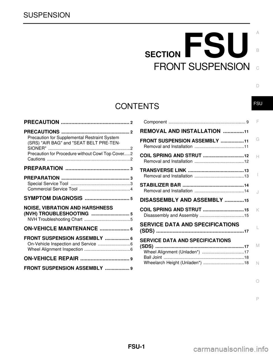
PRECAUTION ...............................................2
PRECAUTIONS ...................................................2
Precaution for Supplemental Restraint System
(SRS) "AIR BAG" and "SEAT BELT PRE-TEN-
SIONER" ...................................................................
2
Precaution for Procedure without Cowl Top Cover ......2
Cautions ....................................................................2
PREPARATION ............................................3
PREPARATION ...................................................3
Special Service Tool .................................................3
Commercial Service Tool ..........................................4
SYMPTOM DIAGNOSIS ...............................5
NOISE, VIBRATION AND HARSHNESS
(NVH) TROUBLESHOOTING .............................
5
NVH Troubleshooting Chart ......................................5
ON-VEHICLE MAINTENANCE .....................6
FRONT SUSPENSION ASSEMBLY ...................6
On-Vehicle Inspection and Service ...........................6
Wheel Alignment Inspection ......................................6
ON-VEHICLE REPAIR ..................................9
FRONT SUSPENSION ASSEMBLY ...................9
Component ...............................................................9
REMOVAL AND INSTALLATION ...............11
FRONT SUSPENSION ASSEMBLY .................11
Removal and Installation .........................................11
COIL SPRING AND STRUT ..............................12
Removal and Installation .........................................12
TRANSVERSE LINK .........................................13
Removal and Installation .........................................13
STABILIZER BAR .............................................14
Removal and Installation .........................................14
DISASSEMBLY AND ASSEMBLY ..............15
COIL SPRING AND STRUT ..............................15
Disassembly and Assembly .....................................15
SERVICE DATA AND SPECIFICATIONS
(SDS) ............................................................
17
SERVICE DATA AND SPECIFICATIONS
(SDS) .................................................................
17
Wheel Alignment (Unladen*) ...................................17
Ball Joint ..................................................................18
Wheelarch Height (Unladen*) ..................................18
Page 3180 of 5883
FSU-4
< PREPARATION >
PREPARATION
Commercial Service Tool
INFOID:0000000001716879
Tool nameDescription
Spring compressor Removing and installing coil spring
Spring gaugeInspecting tranverse link ball joint
Power tool Removing wheel nuts
Removing front suspension component
parts
S-NT717
LST025
PBIC0190E
Page 3186 of 5883
FSU-10
< ON-VEHICLE REPAIR >
FRONT SUSPENSION ASSEMBLY
1. Strut mounting insulator 2. Strut mounting bearing 3. Coil spring
4. Bound bumper 5. Strut 6. Steering knuckle
7. Stabilizer clamp 8. Stabilizer bushing 9. Stabilizer connecting rod
10. Transverse link 11. Stabilizer bar 12. Upper link (left)
13. Upper link (right) 14. Front suspension member 15. Member stay
16. Cap⇐:Front
Refer to GI-3
for the symbols.
Page 3188 of 5883

FSU-12
< REMOVAL AND INSTALLATION >
COIL SPRING AND STRUT
COIL SPRING AND STRUT
Removal and InstallationINFOID:0000000001716888
REMOVAL
1. Remove cowl top panel. Refer to EXT-20, "Removal and Installation" .
2. Remove front tires using power tool.
3. Remove harness of wheel sensor from strut assembly. Refer to BRC-182, "
Removal and Installation" .
CAUTION:
Do not pull on wheel sensor harness.
4. Remove brake hose lock plate. Refer to BR-14, "
Front Brake Tube and Hose" .
5. Remove the nut on the upper side of stabilizer connecting rod using power tool, and then remove stabi-
lizer connecting rod from strut assembly.
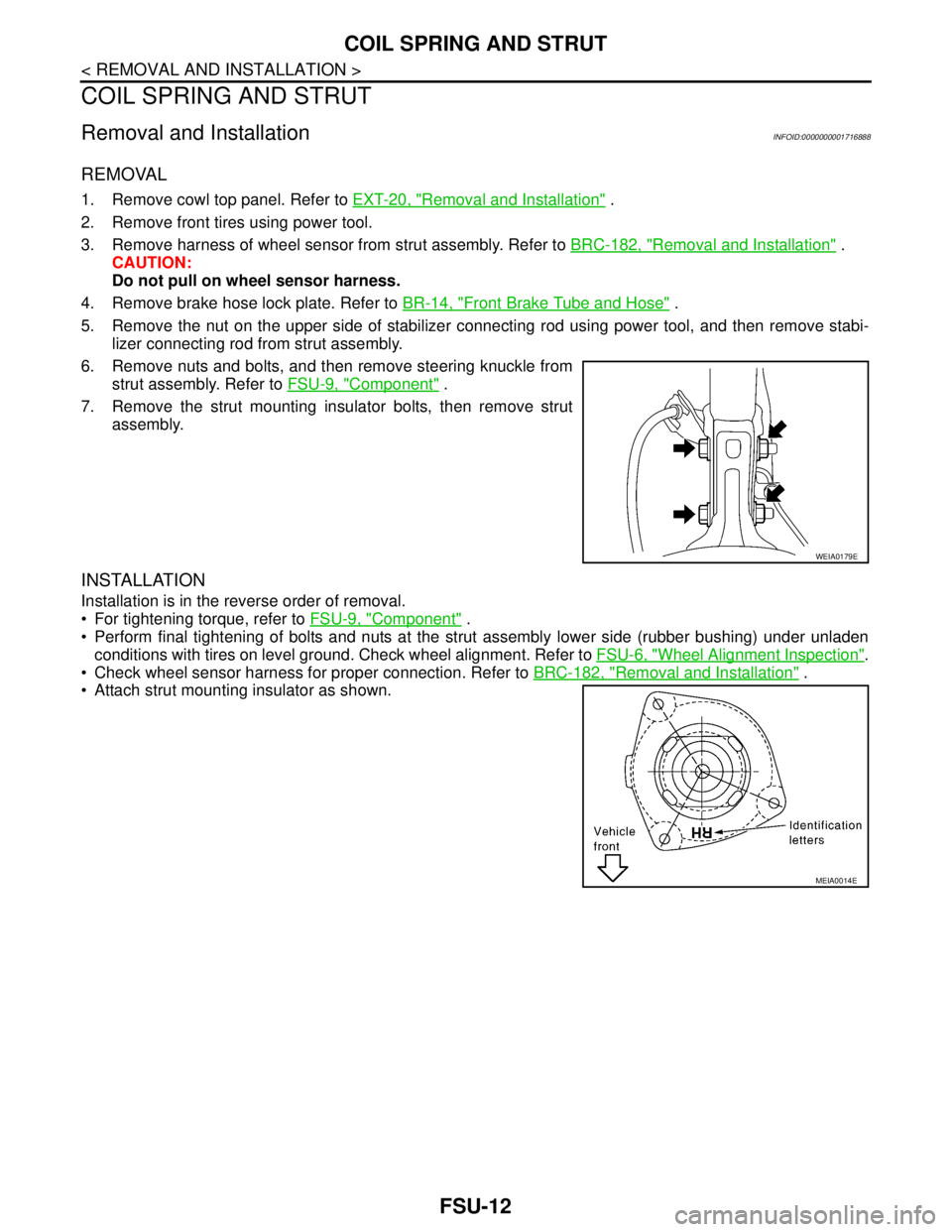
6. Remove nuts and bolts, and then remove steering knuckle from
strut assembly. Refer to FSU-9, "
Component" .
7. Remove the strut mounting insulator bolts, then remove strut
assembly.
INSTALLATION
Installation is in the reverse order of removal.
For tightening torque, refer to FSU-9, "
Component" .
Perform final tightening of bolts and nuts at the strut assembly lower side (rubber bushing) under unladen
conditions with tires on level ground. Check wheel alignment. Refer to FSU-6, "
Wheel Alignment Inspection".
Check wheel sensor harness for proper connection. Refer to BRC-182, "
Removal and Installation" .
Attach strut mounting insulator as shown.
WEIA0179E
MEIA0014E
Page 3191 of 5883

COIL SPRING AND STRUT
FSU-15
< DISASSEMBLY AND ASSEMBLY >
C
D
F
G
H
I
J
K
L
MA
B
FSU
N
O
P
DISASSEMBLY AND ASSEMBLY
COIL SPRING AND STRUT
Disassembly and AssemblyINFOID:0000000001716887
DISASSEMBLY
CAUTION:
Do not damage strut piston rod when removing components from strut assembly.
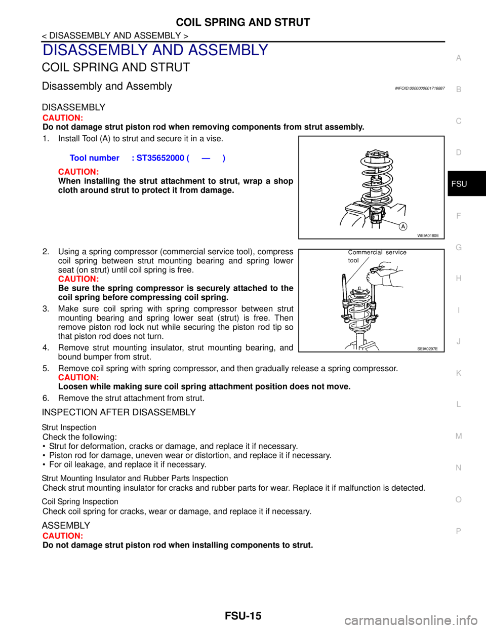
1. Install Tool (A) to strut and secure it in a vise.
CAUTION:
When installing the strut attachment to strut, wrap a shop
cloth around strut to protect it from damage.
2. Using a spring compressor (commercial service tool), compress
coil spring between strut mounting bearing and spring lower
seat (on strut) until coil spring is free.
CAUTION:
Be sure the spring compressor is securely attached to the
coil spring before compressing coil spring.
3. Make sure coil spring with spring compressor between strut
mounting bearing and spring lower seat (strut) is free. Then
remove piston rod lock nut while securing the piston rod tip so
that piston rod does not turn.
4. Remove strut mounting insulator, strut mounting bearing, and
bound bumper from strut.
5. Remove coil spring with spring compressor, and then gradually release a spring compressor.
CAUTION:
Loosen while making sure coil spring attachment position does not move.
6. Remove the strut attachment from strut.
INSPECTION AFTER DISASSEMBLY
Strut Inspection
Check the following:
Strut for deformation, cracks or damage, and replace it if necessary.
Piston rod for damage, uneven wear or distortion, and replace it if necessary.
For oil leakage, and replace it if necessary.
Strut Mounting Insulator and Rubber Parts Inspection
Check strut mounting insulator for cracks and rubber parts for wear. Replace it if malfunction is detected.
Coil Spring Inspection
Check coil spring for cracks, wear or damage, and replace it if necessary.
ASSEMBLY
CAUTION:
Do not damage strut piston rod when installing components to strut. Tool number : ST35652000 ( — )
WEIA0180E
SEIA0297E