Page 5673 of 5883
VTL-12
< ON-VEHICLE REPAIR >[AUTOMATIC AIR CONDITIONER]
A/C UNIT ASSEMBLY
A/C UNIT ASSEMBLY
Removal and InstallationINFOID:0000000001696285
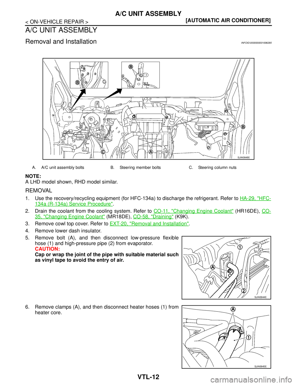
NOTE:
A LHD model shown, RHD model similar.
REMOVAL
1. Use the recovery/recycling equipment (for HFC-134a) to discharge the refrigerant. Refer to HA-29, "HFC-
134a (R-134a) Service Procedure".
2. Drain the coolant from the cooling system. Refer to CO-11, "
Changing Engine Coolant" (HR16DE), CO-
35, "Changing Engine Coolant" (MR18DE), CO-58, "Draining" (K9K).
3. Remove cowl top cover. Refer to EXT-20, "
Removal and Installation".
4. Remove lower dash insulator.
5. Remove bolt (A), and then disconnect low-pressure flexible
hose (1) and high-pressure pipe (2) from evaporator.
CAUTION:
Cap or wrap the joint of the pipe with suitable material such
as vinyl tape to avoid the entry of air.
6. Remove clamps (A), and then disconnect heater hoses (1) from
heater core.
SJIA0648E
A. A/C unit assembly bolts B. Steering member bolts C. Steering column nuts
SJIA0644E
SJIA0645E
Page 5675 of 5883
VTL-14
< ON-VEHICLE REPAIR >[AUTOMATIC AIR CONDITIONER]
A/C UNIT ASSEMBLY
Disassembly and Assembly
INFOID:0000000001696286
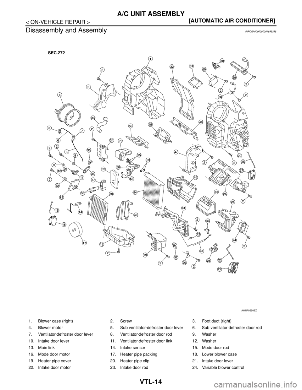
1. Blower case (right) 2. Screw 3. Foot duct (right)
4. Blower motor 5. Sub ventilator·defroster door lever 6. Sub ventilator·defroster door rod
7. Ventilator·defroster door lever 8. Ventilator·defroster door rod 9. Washer
10. Intake door lever 11. Ventilator·defroster door link 12. Washer
13. Main link 14. Intake sensor 15. Mode door rod
16. Mode door motor 17. Heater pipe packing 18. Lower blower case
19. Heater pipe cover 20. Heater pipe clip 21. Intake door lever
22. Intake door motor 23. Intake door rod 24. Variable blower control
AWIIA0590ZZ
Page 5676 of 5883
A/C UNIT ASSEMBLY
VTL-15
< ON-VEHICLE REPAIR >[AUTOMATIC AIR CONDITIONER]
C
D
E
F
G
H
J
K
L
MA
B
VTL
N
O
P
CAUTION:
After installing door motor, perform door motor starting position reset by following self-diagnosis
STEP-3. Refer to HAC-213, "
Front Air Control Self-Diagnosis".
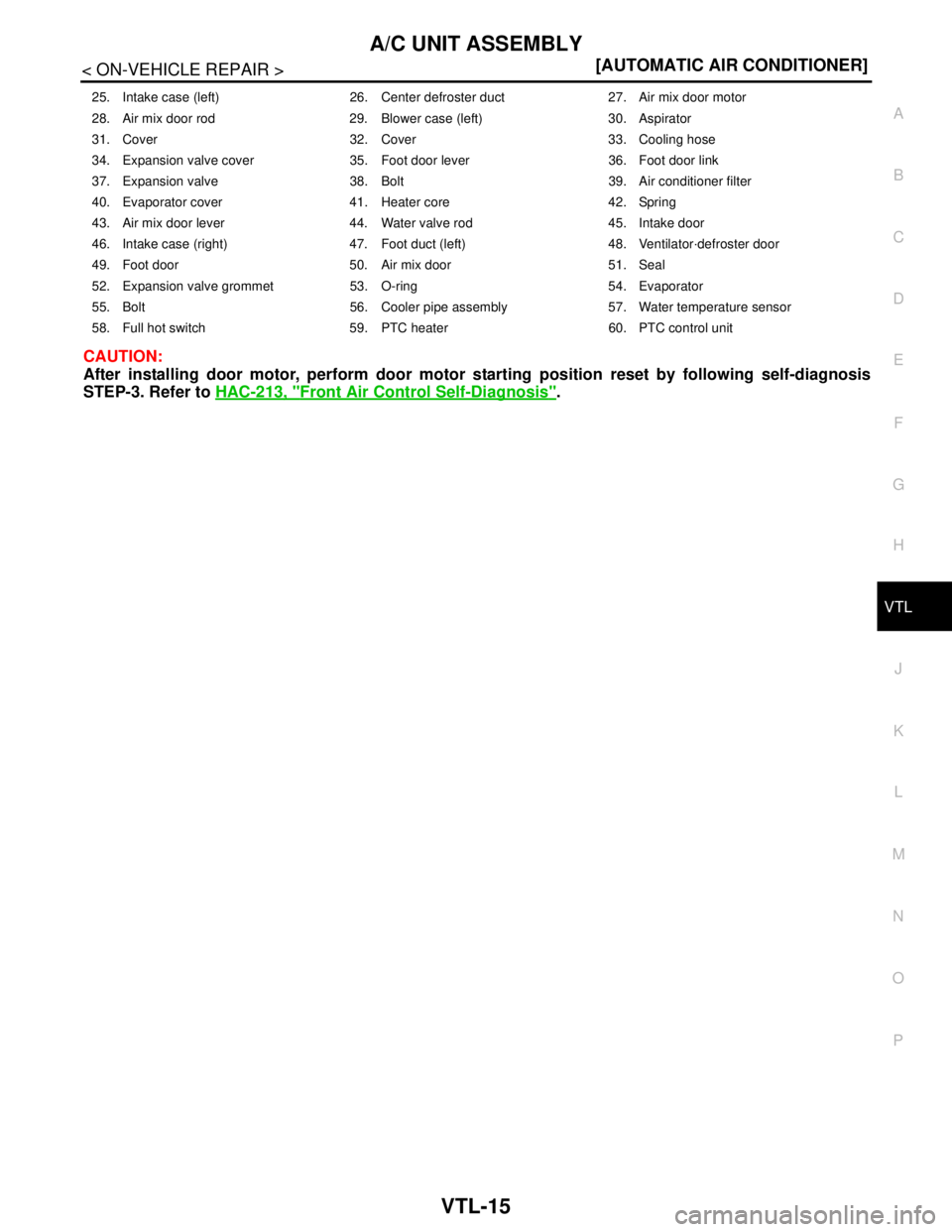
25. Intake case (left) 26. Center defroster duct 27. Air mix door motor
28. Air mix door rod 29. Blower case (left) 30. Aspirator
31. Cover 32. Cover 33. Cooling hose
34. Expansion valve cover 35. Foot door lever 36. Foot door link
37. Expansion valve 38. Bolt 39. Air conditioner filter
40. Evaporator cover 41. Heater core 42. Spring
43. Air mix door lever 44. Water valve rod 45. Intake door
46. Intake case (right) 47. Foot duct (left) 48. Ventilator·defroster door
49. Foot door 50. Air mix door 51. Seal
52. Expansion valve grommet 53. O-ring 54. Evaporator
55. Bolt 56. Cooler pipe assembly 57. Water temperature sensor
58. Full hot switch 59. PTC heater 60. PTC control unit
Page 5678 of 5883
HEATER CORE
VTL-17
< ON-VEHICLE REPAIR >[AUTOMATIC AIR CONDITIONER]
C
D
E
F
G
H
J
K
L
MA
B
VTL
N
O
P
HEATER CORE
Removal and InstallationINFOID:0000000001696357
REMOVAL
1. Remove the A/C unit assembly. Refer to VTL-12, "Removal and Installation".
2. Remove foot duct (left). Refer to VTL-23, "
Removal and Installation".
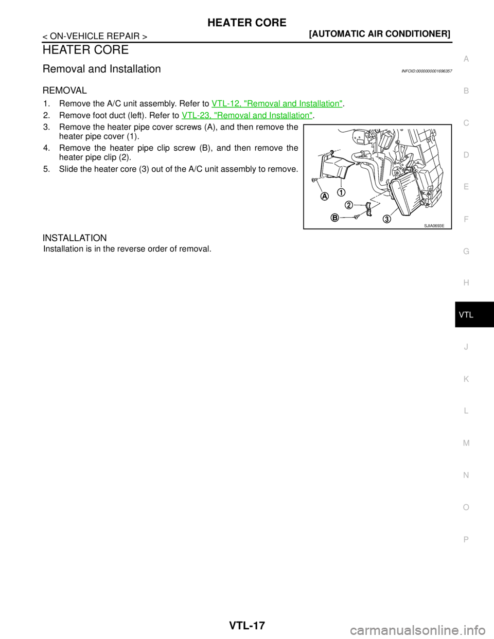
3. Remove the heater pipe cover screws (A), and then remove the
heater pipe cover (1).
4. Remove the heater pipe clip screw (B), and then remove the
heater pipe clip (2).
5. Slide the heater core (3) out of the A/C unit assembly to remove.
INSTALLATION
Installation is in the reverse order of removal.
SJIA0693E
Page 5689 of 5883
VTL-28
< ON-VEHICLE REPAIR >[AUTOMATIC AIR CONDITIONER]
PTC HEATER
PTC HEATER
Removal and Installation of PTC Control UnitINFOID:0000000001696502
REMOVAL
1. Remove the instrument lower finisher and instrument lower cover (LH) for LHD only. Refer to IP-11,
"Removal and Installation".
2. Remove the glove box assembly and instrument lower cover (RH) for RHD only. Refer to IP-11, "
Removal
and Installation".
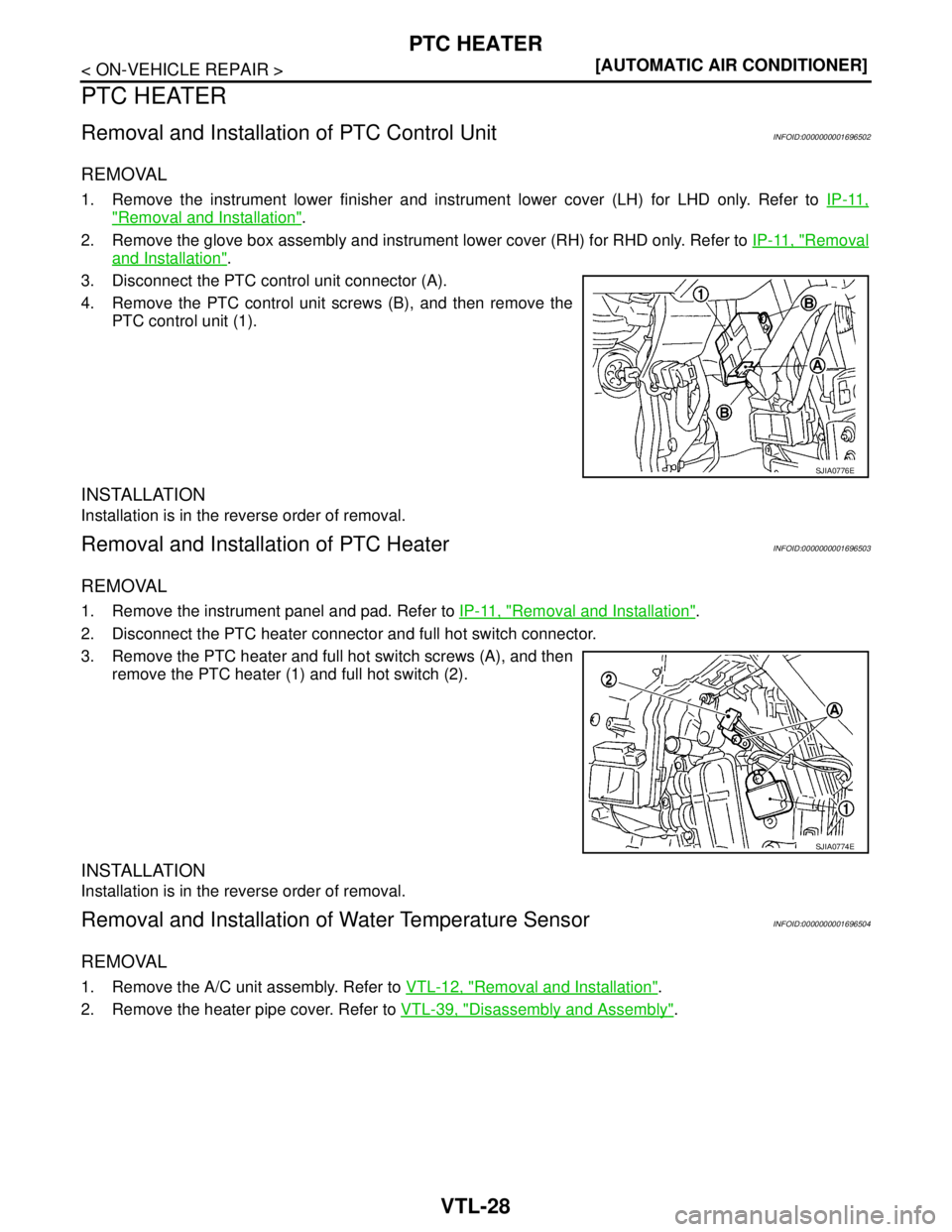
3. Disconnect the PTC control unit connector (A).
4. Remove the PTC control unit screws (B), and then remove the
PTC control unit (1).
INSTALLATION
Installation is in the reverse order of removal.
Removal and Installation of PTC HeaterINFOID:0000000001696503
REMOVAL
1. Remove the instrument panel and pad. Refer to IP-11, "Removal and Installation".
2. Disconnect the PTC heater connector and full hot switch connector.
3. Remove the PTC heater and full hot switch screws (A), and then
remove the PTC heater (1) and full hot switch (2).
INSTALLATION
Installation is in the reverse order of removal.
Removal and Installation of Water Temperature SensorINFOID:0000000001696504
REMOVAL
1. Remove the A/C unit assembly. Refer to VTL-12, "Removal and Installation".
2. Remove the heater pipe cover. Refer to VTL-39, "
Disassembly and Assembly".
SJIA0776E
SJIA0774E
Page 5690 of 5883
PTC HEATER
VTL-29
< ON-VEHICLE REPAIR >[AUTOMATIC AIR CONDITIONER]
C
D
E
F
G
H
J
K
L
MA
B
VTL
N
O
P
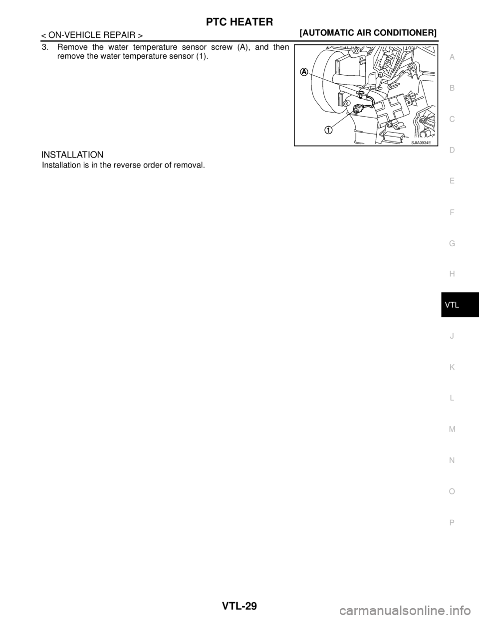
3. Remove the water temperature sensor screw (A), and then
remove the water temperature sensor (1).
INSTALLATION
Installation is in the reverse order of removal.
SJIA0934E
Page 5698 of 5883
A/C UNIT ASSEMBLY
VTL-37
< ON-VEHICLE REPAIR >[MANUAL AIR CONDITIONER]
C
D
E
F
G
H
J
K
L
MA
B
VTL
N
O
P
A/C UNIT ASSEMBLY
Removal and InstallationINFOID:0000000001696531
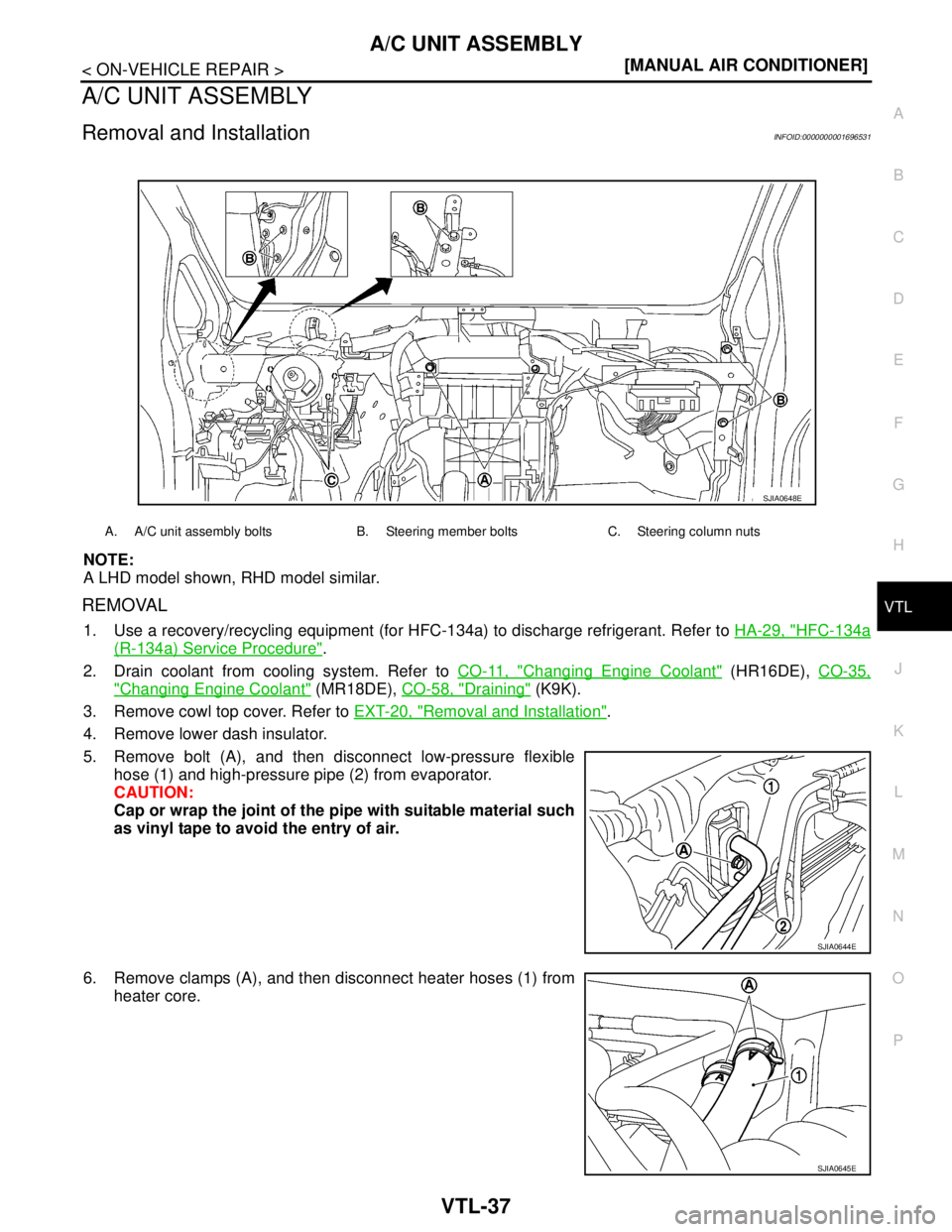
NOTE:
A LHD model shown, RHD model similar.
REMOVAL
1. Use a recovery/recycling equipment (for HFC-134a) to discharge refrigerant. Refer to HA-29, "HFC-134a
(R-134a) Service Procedure".
2. Drain coolant from cooling system. Refer to CO-11, "
Changing Engine Coolant" (HR16DE), CO-35,
"Changing Engine Coolant" (MR18DE), CO-58, "Draining" (K9K).
3. Remove cowl top cover. Refer to EXT-20, "
Removal and Installation".
4. Remove lower dash insulator.
5. Remove bolt (A), and then disconnect low-pressure flexible
hose (1) and high-pressure pipe (2) from evaporator.
CAUTION:
Cap or wrap the joint of the pipe with suitable material such
as vinyl tape to avoid the entry of air.
6. Remove clamps (A), and then disconnect heater hoses (1) from
heater core.
A. A/C unit assembly bolts B. Steering member bolts C. Steering column nuts
SJIA0648E
SJIA0644E
SJIA0645E
Page 5700 of 5883
A/C UNIT ASSEMBLY
VTL-39
< ON-VEHICLE REPAIR >[MANUAL AIR CONDITIONER]
C
D
E
F
G
H
J
K
L
MA
B
VTL
N
O
P
Disassembly and AssemblyINFOID:0000000001696532
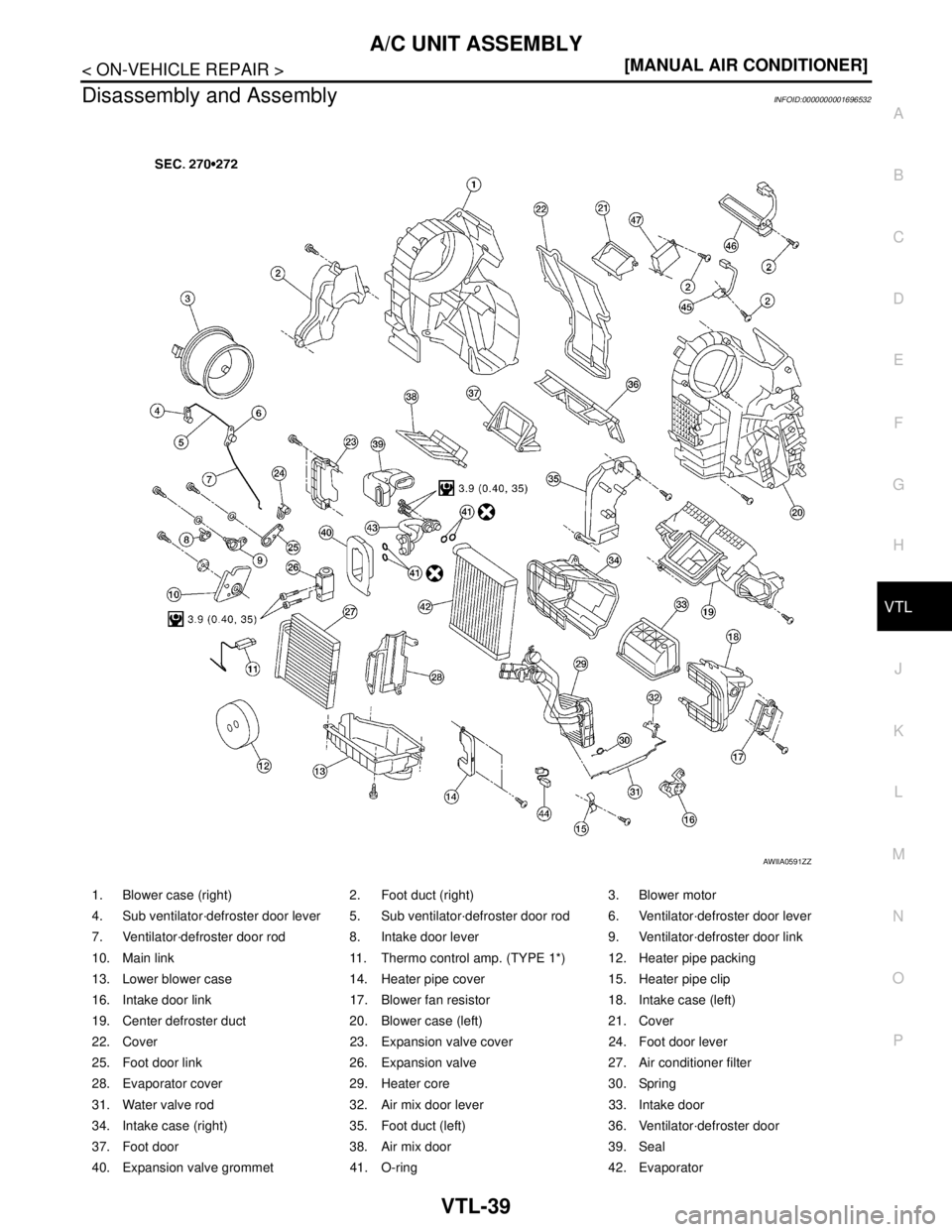
1. Blower case (right) 2. Foot duct (right) 3. Blower motor
4. Sub ventilator·defroster door lever 5. Sub ventilator·defroster door rod 6. Ventilator·defroster door lever
7. Ventilator·defroster door rod 8. Intake door lever 9. Ventilator·defroster door link
10. Main link 11. Thermo control amp. (TYPE 1*) 12. Heater pipe packing
13. Lower blower case 14. Heater pipe cover 15. Heater pipe clip
16. Intake door link 17. Blower fan resistor 18. Intake case (left)
19. Center defroster duct 20. Blower case (left) 21. Cover
22. Cover 23. Expansion valve cover 24. Foot door lever
25. Foot door link 26. Expansion valve 27. Air conditioner filter
28. Evaporator cover 29. Heater core 30. Spring
31. Water valve rod 32. Air mix door lever 33. Intake door
34. Intake case (right) 35. Foot duct (left) 36. Ventilator·defroster door
37. Foot door 38. Air mix door 39. Seal
40. Expansion valve grommet 41. O-ring 42. Evaporator
AWIIA0591ZZ