Page 5701 of 5883
VTL-40
< ON-VEHICLE REPAIR >[MANUAL AIR CONDITIONER]
A/C UNIT ASSEMBLY
43. Cooler pipe assembly 44. Water temperature sensor 45. Full hot switch
46. PTC heater 47. PTC control unit
Page 5703 of 5883
VTL-42
< ON-VEHICLE REPAIR >[MANUAL AIR CONDITIONER]
HEATER CORE
HEATER CORE
Removal and InstallationINFOID:0000000001696534
REMOVAL
1. Remove the A/C unit assembly. Refer to VTL-37, "Removal and Installation".
2. Remove the foot duct (left). Refer to VTL-48, "
Removal and Installation".
3. Remove the heater pipe cover screw, then remove the heater pipe cover.
4. Remove the heater pipe clip screw, then remove the heater pipe clip.
5. Slide the heater core out of the A/C unit assembly.
INSTALLATION
Installation is in the reverse order of removal.
1. Heater pipe cover 2. Heater pipe clip 3. Heater core
A. Heater pipe cover screw B. Heater pipe clip screw
LJIA0200E
Page 5714 of 5883

PTC HEATER
VTL-53
< ON-VEHICLE REPAIR >[MANUAL AIR CONDITIONER]
C
D
E
F
G
H
J
K
L
MA
B
VTL
N
O
P
PTC HEATER
Removal and Installation of PTC Control UnitINFOID:0000000001696541
REMOVAL
1. Remove the instrument lower finisher and instrument lower cover (LH) for LHD only. Refer to IP-11,
"Removal and Installation".
2. Remove the glove box assembly and instrument lower cover (RH) for RHD only. Refer to IP-11, "
Removal
and Installation".
3. Disconnect connector (A).
4. Remove mounting screws (B), and then remove PTC control
unit (1).
INSTALLATION
Installation is basically the reverse order of removal.
Removal and Installation of PTC HeaterINFOID:0000000001696542
REMOVAL
1. Remove instrument panel and pad. Refer to IP-11, "Removal and Installation".
2. Disconnect PTC heater connector and full hot switch connector.
3. Remove mounting screws (A), and then remove PTC heater (1)
and full hot switch (2).
INSTALLATION
Installation is basically the reverse order of removal.
Removal and Installation of Water Temperature SensorINFOID:0000000001696543
REMOVAL
1. Remove A/C unit assembly. Refer to VTL-37, "Removal and Installation".
2. Remove heater pipe cover. Refer to VTL-39, "
Disassembly and Assembly".
SJIA0776E
SJIA0774E
Page 5715 of 5883
VTL-54
< ON-VEHICLE REPAIR >[MANUAL AIR CONDITIONER]
PTC HEATER
3. Remove mounting screw (A), and then remove water tempera-
ture sensor (1).
INSTALLATION
Installation is basically the reverse order of removal.
SJIA0934E
Page 5783 of 5883
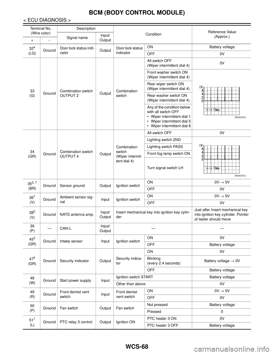
WCS-68
< ECU DIAGNOSIS >
BCM (BODY CONTROL MODULE)
324
(LG)GroundDoor lock status indi-
catorOutputDoor lock status
indicatorON Battery voltage
OFF 0V
33
(G)GroundCombination switch
OUTPUT 2OutputCombination
switchAll switch OFF
(Wiper intermittent dial 4)0V
Front washer switch ON
(Wiper intermittent dial 4)
Rear wiper switch ON
(Wiper intermittent dial 4)
Rear washer switch ON
(Wiper intermittent dial 4)
Any of the condition below
with all switch OFF
Wiper intermittent dial 1
Wiper intermittent dial 5
Wiper intermittent dial 6
34
(GR)GroundCombination switch
OUTPUT 4OutputCombination
switch
(Wiper intermit-
tent dial 4)All switch OFF 0V
Lighting switch 2ND
Lighting switch PASS
Front fog lamp switch ON
Turn signal switch LH
35
3, 7
(BR)Ground Sensor ground Output Ignition switchON 0V → 5V
OFF 0V
36
7
(V)GroundAmbient sensor sig-
nalInput Ignition switchON 0V → 5V
OFF 0V
38
5
(V)Ground NATS antenna amp.Input/
OutputInsert mechanical key into ignition key cylin-
derJust after Insert mechanical key
into ignition key cylinder. Pointer
of tester should move
39
(P)—CAN-LInput/
Output——
45
3
(GR)Ground Intake sensor Input Ignition switchON 0V
OFF Battery voltage
47
5
(GR)Ground Security indicator OutputSecurity indica-
torON 0V
Blinking
(every 2.4 seconds)Battery voltage → 0V
OFF Battery voltage
48
(W)Ground Start power supply InputIgnition switch START Battery voltage
Other than above 0V
49
(R)GroundFront demist vent
switchInputFront demist
vent switchON 0V → 5V
OFF 0V
50
(P)Ground Fan switch Output Fan switchNot pressed Battery voltage
Pressed 0
51
7
(L)Ground PTC relay 3 control Output Ignition ONPTC heater 3 ON 0V
PTC heater 3 OFF Battery voltage Te r m i n a l N o .
(Wire color)Description
ConditionReference Value
(Approx.)
Signal nameInput/
Output +−
SKIA2167J
SKIA2167J
Page 5784 of 5883
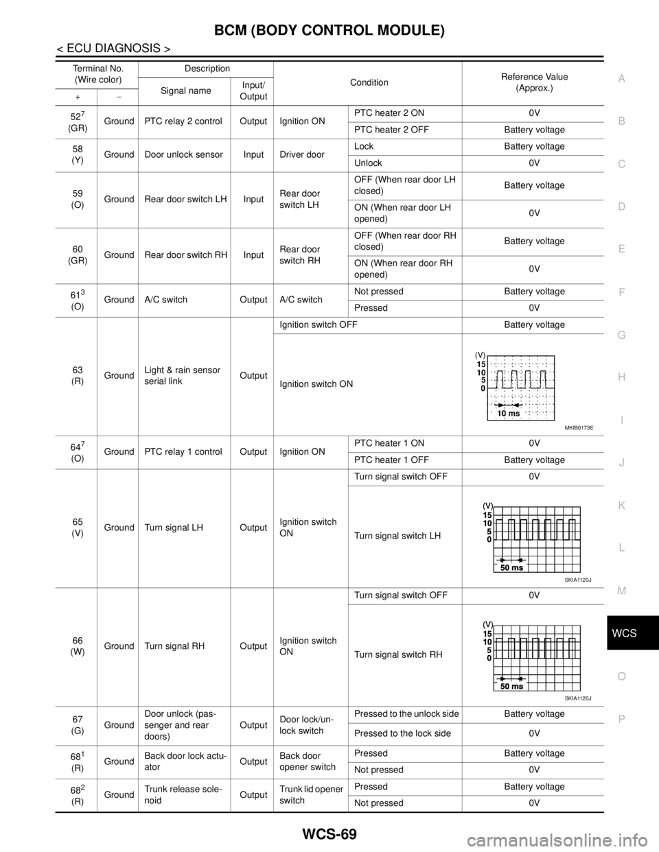
WCS
BCM (BODY CONTROL MODULE)
WCS-69
< ECU DIAGNOSIS >
C
D
E
F
G
H
I
J
K
L
MB A
O
P
527
(GR)Ground PTC relay 2 control Output Ignition ONPTC heater 2 ON 0V
PTC heater 2 OFF Battery voltage
58
(Y)Ground Door unlock sensor Input Driver doorLock Battery voltage
Unlock 0V
59
(O)Ground Rear door switch LH InputRear door
switch LHOFF (When rear door LH
closed) Battery voltage
ON (When rear door LH
opened)0V
60
(GR)Ground Rear door switch RH InputRear door
switch RHOFF (When rear door RH
closed) Battery voltage
ON (When rear door RH
opened)0V
61
3
(O)Ground A/C switch Output A/C switchNot pressed Battery voltage
Pressed 0V
63
(R)GroundLight & rain sensor
serial linkOutputIgnition switch OFF Battery voltage
Ignition switch ON
64
7
(O)Ground PTC relay 1 control Output Ignition ONPTC heater 1 ON 0V
PTC heater 1 OFF Battery voltage
65
(V)Ground Turn signal LH OutputIgnition switch
ONTurn signal switch OFF 0V
Turn signal switch LH
66
(W)Ground Turn signal RH OutputIgnition switch
ONTurn signal switch OFF 0V
Turn signal switch RH
67
(G)GroundDoor unlock (pas-
senger and rear
doors)OutputDoor lock/un-
lock switchPressed to the unlock side Battery voltage
Pressed to the lock side 0V
68
1
(R)GroundBack door lock actu-
atorOutputBack door
opener switchPressed Battery voltage
Not pressed 0V
68
2
(R)GroundTrunk release sole-
noidOutputTrunk lid opener
switchPressed Battery voltage
Not pressed 0V Terminal No.
(Wire color)Description
ConditionReference Value
(Approx.)
Signal nameInput/
Output +−
MKIB0173E
SKIA1120J
SKIA1120J


