2007 NISSAN TIIDA Heater
[x] Cancel search: HeaterPage 4374 of 5883
MWI
BCM (BODY CONTROL MODULE)
MWI-67
< ECU DIAGNOSIS >
C
D
E
F
G
H
I
J
K
L
MB A
O
P
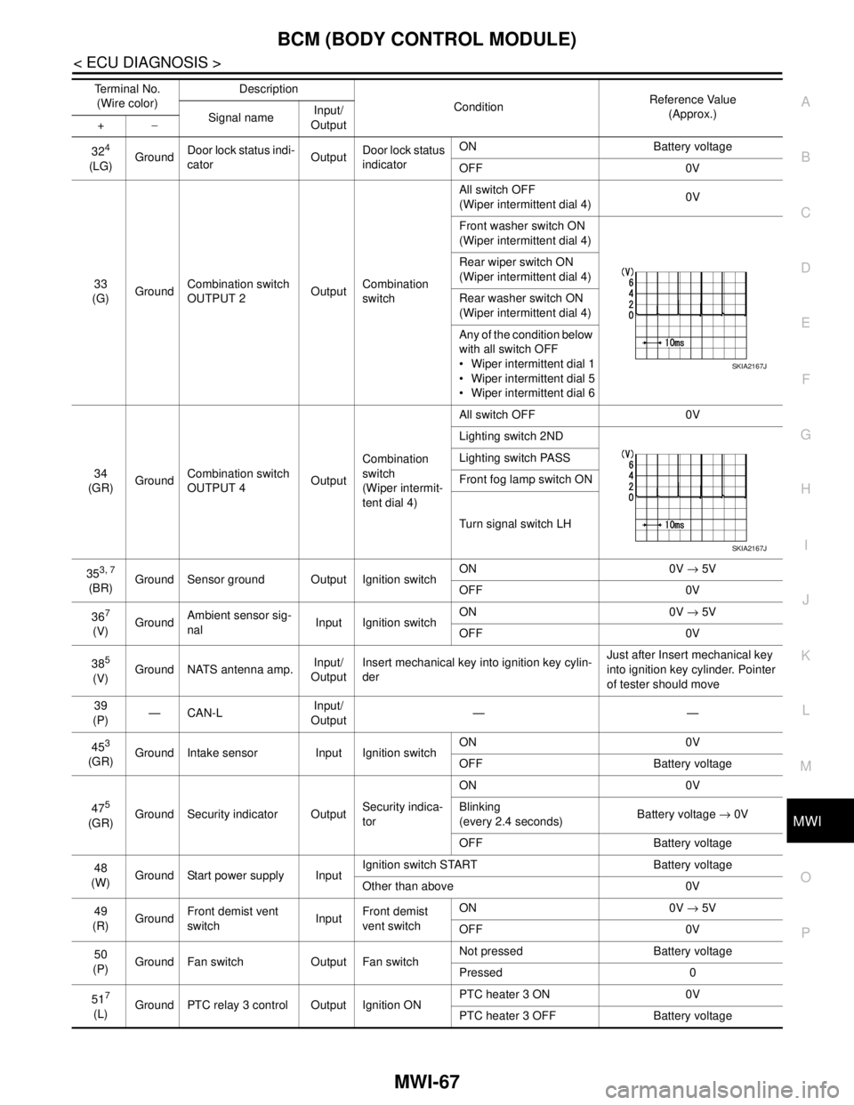
324
(LG)GroundDoor lock status indi-
catorOutputDoor lock status
indicatorON Battery voltage
OFF 0V
33
(G)GroundCombination switch
OUTPUT 2OutputCombination
switchAll switch OFF
(Wiper intermittent dial 4)0V
Front washer switch ON
(Wiper intermittent dial 4)
Rear wiper switch ON
(Wiper intermittent dial 4)
Rear washer switch ON
(Wiper intermittent dial 4)
Any of the condition below
with all switch OFF
Wiper intermittent dial 1
Wiper intermittent dial 5
Wiper intermittent dial 6
34
(GR)GroundCombination switch
OUTPUT 4OutputCombination
switch
(Wiper intermit-
tent dial 4)All switch OFF 0V
Lighting switch 2ND
Lighting switch PASS
Front fog lamp switch ON
Turn signal switch LH
35
3, 7
(BR)Ground Sensor ground Output Ignition switchON 0V → 5V
OFF 0V
36
7
(V)GroundAmbient sensor sig-
nalInput Ignition switchON 0V → 5V
OFF 0V
38
5
(V)Ground NATS antenna amp.Input/
OutputInsert mechanical key into ignition key cylin-
derJust after Insert mechanical key
into ignition key cylinder. Pointer
of tester should move
39
(P)—CAN-LInput/
Output——
45
3
(GR)Ground Intake sensor Input Ignition switchON 0V
OFF Battery voltage
47
5
(GR)Ground Security indicator OutputSecurity indica-
torON 0V
Blinking
(every 2.4 seconds)Battery voltage → 0V
OFF Battery voltage
48
(W)Ground Start power supply InputIgnition switch START Battery voltage
Other than above 0V
49
(R)GroundFront demist vent
switchInputFront demist
vent switchON 0V → 5V
OFF 0V
50
(P)Ground Fan switch Output Fan switchNot pressed Battery voltage
Pressed 0
51
7
(L)Ground PTC relay 3 control Output Ignition ONPTC heater 3 ON 0V
PTC heater 3 OFF Battery voltage Terminal No.
(Wire color)Description
ConditionReference Value
(Approx.)
Signal nameInput/
Output +−
SKIA2167J
SKIA2167J
Page 4375 of 5883
MWI-68
< ECU DIAGNOSIS >
BCM (BODY CONTROL MODULE)
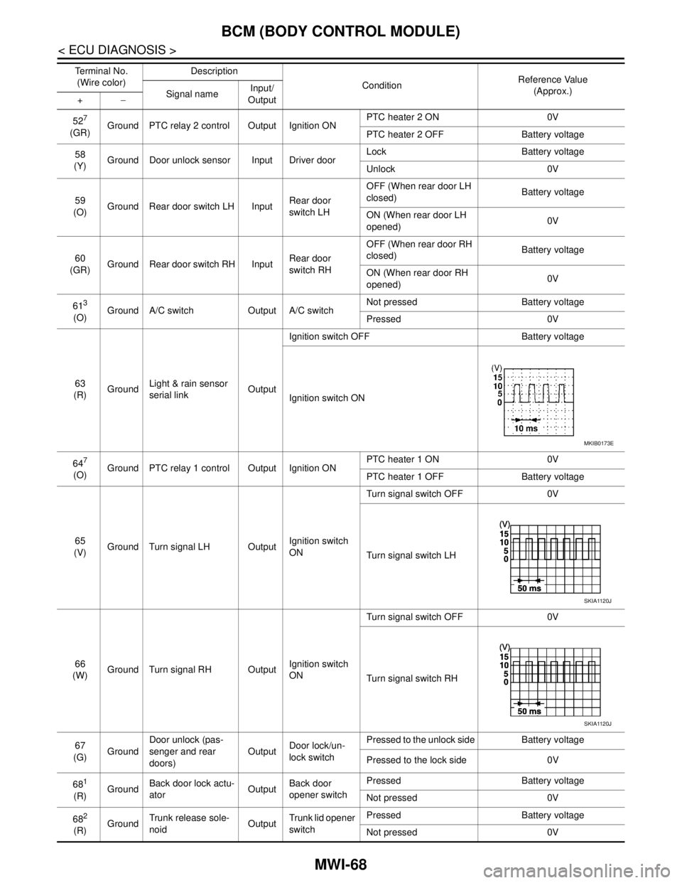
527
(GR)Ground PTC relay 2 control Output Ignition ONPTC heater 2 ON 0V
PTC heater 2 OFF Battery voltage
58
(Y)Ground Door unlock sensor Input Driver doorLock Battery voltage
Unlock 0V
59
(O)Ground Rear door switch LH InputRear door
switch LHOFF (When rear door LH
closed) Battery voltage
ON (When rear door LH
opened)0V
60
(GR)Ground Rear door switch RH InputRear door
switch RHOFF (When rear door RH
closed) Battery voltage
ON (When rear door RH
opened)0V
61
3
(O)Ground A/C switch Output A/C switchNot pressed Battery voltage
Pressed 0V
63
(R)GroundLight & rain sensor
serial linkOutputIgnition switch OFF Battery voltage
Ignition switch ON
64
7
(O)Ground PTC relay 1 control Output Ignition ONPTC heater 1 ON 0V
PTC heater 1 OFF Battery voltage
65
(V)Ground Turn signal LH OutputIgnition switch
ONTurn signal switch OFF 0V
Turn signal switch LH
66
(W)Ground Turn signal RH OutputIgnition switch
ONTurn signal switch OFF 0V
Turn signal switch RH
67
(G)GroundDoor unlock (pas-
senger and rear
doors)OutputDoor lock/un-
lock switchPressed to the unlock side Battery voltage
Pressed to the lock side 0V
68
1
(R)GroundBack door lock actu-
atorOutputBack door
opener switchPressed Battery voltage
Not pressed 0V
68
2
(R)GroundTrunk release sole-
noidOutputTrunk lid opener
switchPressed Battery voltage
Not pressed 0V Te r m i n a l N o .
(Wire color)Description
ConditionReference Value
(Approx.)
Signal nameInput/
Output +−
MKIB0173E
SKIA1120J
SKIA1120J
Page 4640 of 5883

DIAGNOSIS SYSTEM (BCM)
SEC-15
< FUNCTION DIAGNOSIS >[WITH INTELLIGENT KEY SYSTEM]
C
D
E
F
G
H
I
J
L
MA
B
SEC
N
O
P
DIAGNOSIS SYSTEM (BCM)
COMMON ITEM
COMMON ITEM : CONSULT-III Function (BCM - COMMON ITEM)INFOID:0000000001404046
APPLICATION ITEM
CONSULT-III performs the following functions via CAN communication with BCM.
SYSTEM APPLICATION
BCM can perform the following functions for each system.
NOTE:
It can perform the diagnosis modes except the following for all sub system selection items.
IMMU
IMMU : CONSULT-III Function (BCM - IMMU)INFOID:0000000001404047
APPLICATION ITEM
CONSULT-III performs the following functions via CAN communication with BCM.
Diagnosis mode Function Description
WORK SUPPORT Changes the setting for each system function.
SELF-DIAG RESULTS Displays the diagnosis results judged by BCM. Refer to XX-XX, "*****"
.
CAN DIAG SUPPORT MNTR Monitors the reception status of CAN communication viewed from BCM.
DATA MONITOR The BCM input/output signals are displayed.
ACTIVE TEST The signals used to activate each device are forcibly supplied from BCM.
ECU IDENTIFICATION The BCM part number is displayed.
CONFIGURATION Enables to read and save the vehicle specification.
Enables to write the vehicle specification when replacing BCM.
System Sub system selection itemDiagnosis mode
WORK SUPPORT DATA MONITOR ACTIVE TEST
—BCM×
Door lock DOOR LOCK×××
Rear window defogger REAR DEFOGGER××
Warning chime BUZZER××
Interior room lamp timer INT LAMP×××
Remote keyless entry system MULTI REMOTE ENT×××
Exterior lamp HEAD LAMP×××
Wiper and washer WIPER×××
Turn signal and hazard warning lamps FLASHER××
Air conditioner AIR CONDITONER×
Intelligent Key system INTELLIGENT KEY×
Combination switch COMB SW×
Immobilizer IMMU××
Interior room lamp battery saver BATTERY SAVER×××
Trunk open TRUNK×
Vehicle security system THEFT ALM×××
Signal buffer system SIGNAL BUFFER××
PTC heater system PTC HEATER××
Page 4698 of 5883

IPDM E/R (INTELLIGENT POWER DISTRIBUTION MODULE ENGINE ROOM)
SEC-73
< ECU DIAGNOSIS >[WITH INTELLIGENT KEY SYSTEM]
C
D
E
F
G
H
I
J
L
MA
B
SEC
N
O
P
IPDM E/R (INTELLIGENT POWER DISTRIBUTION MODULE ENGINE
ROOM)
Reference ValueINFOID:0000000001404135
Refer to IPDM E/R.
Fail SafeINFOID:0000000001404139
CAN communication control
When CAN communication with ECM and BCM is impossible, IPDM E/R performs fail-safe control. After CAN
communication recovers normally, it also returns to normal control.
If no CAN communication is available with ECM
*1: HR engine models
*2: MR engine and K9K engine models
If no CAN communication is available with BCM
Ignition relay malfunction detection function
IPDM E/R monitors the voltage at the contact circuit and excitation coil circuit of the ignition relay inside it.
IPDM E/R judges the ignition relay error if the voltage differs between the contact circuit and the excitation
coil circuit.
If the ignition relay cannot turn OFF due to contact seizure, it activates the tail lamp relay for 10 minutes to
alert the user to the ignition relay malfunction when the ignition switch is turned OFF.
Control part Fail-safe in operation
Cooling fan The cooling fan relay-2*
1 or the cooling fan relay-3*2 turns ON when the ignition switch
is turned ON
Turns off the fan motor low relay when the ignition switch is turned OFF
A/C compressor A/C relay OFF
Control part Fail-safe in operation
Headlamp The headlamp low relay turns ON when the ignition switch is turned ON
The headlamp low relay turns OFF when the ignition switch is turned OFF
Headlamp high relay OFF
Parking lamps
License plate lamps
Tail lamps
Illuminations The tail lamp relay turns ON when the ignition switch is turned ON
The tail lamp relay turns OFF when the ignition switch is turned OFF
Front wiper The status just before activation of fail-safe control is maintained until the ignition
switch is turned OFF while the front wiper is operating at LO or HI speed.
The front wiper is operated at LO speed until the ignition switch is turned OFF if the
fail-safe control is activated while the front wiper is set in the INT mode and the front
wiper motor is operating.
Front fog lamps Front fog lamp relay OFF
Starter motor Inhibit relay OFF
Rear window defogger Rear window defogger relay OFF
Headlamp washer Headlamp washer relay OFF
PTC heater PTC heater relay OFF
DTC Ignition switch Ignition relay Tail lamp relay
—ONON—
—OFFOFF—
B2098: IGN RLY ON OFF ON ON (10 minutes)
B2099: IGN RLY OFF ON OFF —
Page 4712 of 5883

DIAGNOSIS SYSTEM (BCM)
SEC-87
< FUNCTION DIAGNOSIS >[WITHOUT INTELLIGENT KEY SYSTEM]
C
D
E
F
G
H
I
J
L
MA
B
SEC
N
O
P
DIAGNOSIS SYSTEM (BCM)
COMMON ITEM
COMMON ITEM : CONSULT-III Function (BCM - COMMON ITEM)INFOID:0000000001404165
APPLICATION ITEM
CONSULT-III performs the following functions via CAN communication with BCM.
SYSTEM APPLICATION
BCM can perform the following functions for each system.
NOTE:
It can perform the diagnosis modes except the following for all sub system selection items.
IMMU
IMMU : CONSULT-III Function (BCM - IMMU)INFOID:0000000001404166
APPLICATION ITEM
CONSULT-III performs the following functions via CAN communication with BCM.
Diagnosis mode Function Description
WORK SUPPORT Changes the setting for each system function.
SELF-DIAG RESULTS Displays the diagnosis results judged by BCM. Refer to XX-XX, "*****"
.
CAN DIAG SUPPORT MNTR Monitors the reception status of CAN communication viewed from BCM.
DATA MONITOR The BCM input/output signals are displayed.
ACTIVE TEST The signals used to activate each device are forcibly supplied from BCM.
ECU IDENTIFICATION The BCM part number is displayed.
CONFIGURATION Enables to read and save the vehicle specification.
Enables to write the vehicle specification when replacing BCM.
System Sub system selection itemDiagnosis mode
WORK SUPPORT DATA MONITOR ACTIVE TEST
—BCM×
Door lock DOOR LOCK×××
Rear window defogger REAR DEFOGGER××
Warning chime BUZZER××
Interior room lamp timer INT LAMP×××
Remote keyless entry system MULTI REMOTE ENT×××
Exterior lamp HEAD LAMP×××
Wiper and washer WIPER×××
Turn signal and hazard warning lamps FLASHER××
Air conditioner AIR CONDITONER×
Combination switch COMB SW×
Immobilizer IMMU××
Interior room lamp battery saver BATTERY SAVER×××
Trunk open TRUNK×
Vehicle security system THEFT ALM×××
Signal buffer system SIGNAL BUFFER××
PTC heater system PTC HEATER××
Page 4739 of 5883

SEC-114
< ECU DIAGNOSIS >[WITHOUT INTELLIGENT KEY SYSTEM]
IPDM E/R (INTELLIGENT POWER DISTRIBUTION MODULE ENGINE ROOM)
IPDM E/R (INTELLIGENT POWER DISTRIBUTION MODULE ENGINE
ROOM)
Reference ValueINFOID:0000000001404226
Refer to IPDM E/R.
Fail SafeINFOID:0000000001404229
CAN communication control
When CAN communication with ECM and BCM is impossible, IPDM E/R performs fail-safe control. After CAN
communication recovers normally, it also returns to normal control.
If no CAN communication is available with ECM
*1: HR engine models
*2: MR engine and K9K engine models
If no CAN communication is available with BCM
Ignition relay malfunction detection function
IPDM E/R monitors the voltage at the contact circuit and excitation coil circuit of the ignition relay inside it.
IPDM E/R judges the ignition relay error if the voltage differs between the contact circuit and the excitation
coil circuit.
If the ignition relay cannot turn OFF due to contact seizure, it activates the tail lamp relay for 10 minutes to
alert the user to the ignition relay malfunction when the ignition switch is turned OFF.
Control part Fail-safe in operation
Cooling fan The cooling fan relay-2*
1 or the cooling fan relay-3*2 turns ON when the ignition switch
is turned ON
Turns off the fan motor low relay when the ignition switch is turned OFF
A/C compressor A/C relay OFF
Control part Fail-safe in operation
Headlamp The headlamp low relay turns ON when the ignition switch is turned ON
The headlamp low relay turns OFF when the ignition switch is turned OFF
Headlamp high relay OFF
Parking lamps
License plate lamps
Tail lamps
Illuminations The tail lamp relay turns ON when the ignition switch is turned ON
The tail lamp relay turns OFF when the ignition switch is turned OFF
Front wiper The status just before activation of fail-safe control is maintained until the ignition
switch is turned OFF while the front wiper is operating at LO or HI speed.
The front wiper is operated at LO speed until the ignition switch is turned OFF if the
fail-safe control is activated while the front wiper is set in the INT mode and the front
wiper motor is operating.
Front fog lamps Front fog lamp relay OFF
Starter motor Inhibit relay OFF
Rear window defogger Rear window defogger relay OFF
Headlamp washer Headlamp washer relay OFF
PTC heater PTC heater relay OFF
DTC Ignition switch Ignition relay Tail lamp relay
—ONON—
—OFFOFF—
B2098: IGN RLY ON OFFONON (10 minutes)
B2099: IGN RLY OFF ON OFF —
Page 5662 of 5883
VTL-1
VENTILATION, HEATER & AIR CONDITIONER
C
D
E
F
G
H
J
K
L
M
SECTION VTL
A
B
VTL
N
O
P
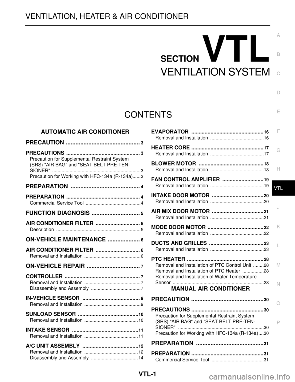
CONTENTS
VENTILATION SYSTEM
AUTOMATIC AIR CONDITIONER
PRECAUTION ...............................................
3
PRECAUTIONS ...................................................3
Precaution for Supplemental Restraint System
(SRS) "AIR BAG" and "SEAT BELT PRE-TEN-
SIONER" ...................................................................
3
Precaution for Working with HFC-134a (R-134a) ......3
PREPARATION ............................................4
PREPARATION ...................................................4
Commercial Service Tool ..........................................4
FUNCTION DIAGNOSIS ...............................5
AIR CONDITIONER FILTER ...............................5
Description ................................................................5
ON-VEHICLE MAINTENANCE .....................6
AIR CONDITIONER FILTER ...............................6
Removal and Installation ...........................................6
ON-VEHICLE REPAIR ..................................7
CONTROLLER ....................................................7
Removal and Installation ...........................................7
Disassembly and Assembly ......................................7
IN-VEHICLE SENSOR ........................................9
Removal and Installation ...........................................9
SUNLOAD SENSOR ..........................................10
Removal and Installation .........................................10
INTAKE SENSOR ..............................................11
Removal and Installation .........................................11
A/C UNIT ASSEMBLY .......................................12
Removal and Installation .........................................12
Disassembly and Assembly ....................................14
EVAPORATOR .................................................16
Removal and Installation .........................................16
HEATER CORE .................................................17
Removal and Installation .........................................17
BLOWER MOTOR ............................................18
Removal and Installation .........................................18
FAN CONTROL AMPLIFIER ............................19
Removal and Installation .........................................19
INTAKE DOOR MOTOR ...................................20
Removal and Installation .........................................20
AIR MIX DOOR MOTOR ...................................21
Removal and Installation .........................................21
MODE DOOR MOTOR ......................................22
Removal and Installation .........................................22
DUCTS AND GRILLES .....................................23
Removal and Installation .........................................23
PTC HEATER ....................................................28
Removal and Installation of PTC Control Unit .........28
Removal and Installation of PTC Heater .................28
Removal and Installation of Water Temperature
Sensor .....................................................................
28
MANUAL AIR CONDITIONER
PRECAUTION ..............................................
30
PRECAUTIONS .................................................30
Precaution for Supplemental Restraint System
(SRS) "AIR BAG" and "SEAT BELT PRE-TEN-
SIONER" .................................................................
30
Precaution for Working with HFC-134a (R-134a) ....30
PREPARATION ...........................................31
PREPARATION .................................................31
Commercial Service Tool ........................................31
Page 5663 of 5883
VTL-2
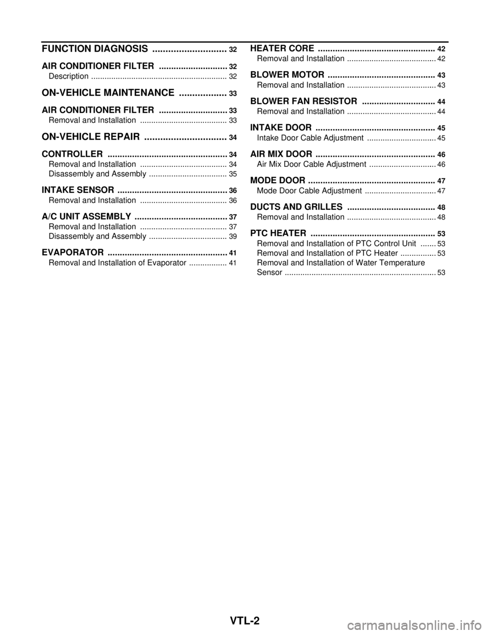
FUNCTION DIAGNOSIS .............................32
AIR CONDITIONER FILTER .............................32
Description ..............................................................32
ON-VEHICLE MAINTENANCE ...................33
AIR CONDITIONER FILTER .............................33
Removal and Installation ........................................33
ON-VEHICLE REPAIR ................................34
CONTROLLER ..................................................34
Removal and Installation ........................................34
Disassembly and Assembly ....................................35
INTAKE SENSOR ..............................................36
Removal and Installation ........................................36
A/C UNIT ASSEMBLY .......................................37
Removal and Installation ........................................37
Disassembly and Assembly ....................................39
EVAPORATOR ..................................................41
Removal and Installation of Evaporator ..................41
HEATER CORE .................................................42
Removal and Installation .........................................42
BLOWER MOTOR .............................................43
Removal and Installation .........................................43
BLOWER FAN RESISTOR ...............................44
Removal and Installation .........................................44
INTAKE DOOR ..................................................45
Intake Door Cable Adjustment ................................45
AIR MIX DOOR ..................................................46
Air Mix Door Cable Adjustment ...............................46
MODE DOOR .....................................................47
Mode Door Cable Adjustment .................................47
DUCTS AND GRILLES .....................................48
Removal and Installation .........................................48
PTC HEATER ....................................................53
Removal and Installation of PTC Control Unit ........53
Removal and Installation of PTC Heater .................53
Removal and Installation of Water Temperature
Sensor .....................................................................
53