2007 NISSAN TIIDA Trunk
[x] Cancel search: TrunkPage 3688 of 5883
SQUEAK AND RATTLE TROUBLE DIAGNOSIS
INT-9
< PREPARATION >
C
D
E
F
G
H
I
K
L
MA
B
INT
N
O
P
SILICONE GREASE
Used in place of UHMW tape that will be visible or not fit.
Note: Will only last a few months.
SILICONE SPRAY
Use when grease cannot be applied.
DUCT TAPE
Use to eliminate movement.
CONFIRM THE REPAIR
Confirm that the cause of a noise is repaired by test driving the vehicle. Operate the vehicle under the same
conditions as when the noise originally occurred. Refer to the notes on the Diagnostic Worksheet.
Generic Squeak and Rattle TroubleshootingINFOID:0000000001329047
Refer to Table of Contents for specific component removal and installation information.
INSTRUMENT PANEL
Most incidents are caused by contact and movement between:
1. The cluster lid A and instrument panel
2. Acrylic lens and combination meter housing
3. Instrument panel to front pillar garnish
4. Instrument panel to windshield
5. Instrument panel pins
6. Wiring harnesses behind the combination meter
7. A/C defroster duct and duct joint
These incidents can usually be located by tapping or moving the components to duplicate the noise or by
pressing on the components while driving to stop the noise. Most of these incidents can be repaired by apply-
ing felt cloth tape or silicone spray (in hard to reach areas). Urethane pads can be used to insulate wiring har-
ness.
CAUTION:
Do not use silicone spray to isolate a squeak or rattle. If you saturate the area with silicone, you will
not be able to recheck the repair.
CENTER CONSOLE
Components to pay attention to include:
1. Shifter assembly cover to finisher
2. A/C control unit and cluster lid C
3. Wiring harnesses behind audio and A/C control unit
The instrument panel repair and isolation procedures also apply to the center console.
DOORS
Pay attention to the:
1. Finisher and inner panel making a slapping noise
2. Inside handle escutcheon to door finisher
3. Wiring harnesses tapping
4. Door striker out of alignment causing a popping noise on starts and stops
Tapping or moving the components or pressing on them while driving to duplicate the conditions can isolate
many of these incidents. You can usually insulate the areas with felt cloth tape or insulator foam blocks from
the NISSAN Squeak and Rattle Kit (J-43980) to repair the noise.
TRUNK
Trunk noises are often caused by a loose jack or loose items put into the trunk by the owner.
In addition look for:
1. Trunk lid bumpers out of adjustment
2. Trunk lid striker out of adjustment
3. The trunk lid torsion bars knocking together
4. A loose license plate or bracket
Page 3696 of 5883
TRUNK LID FINISHER
INT-17
< ON-VEHICLE REPAIR >
C
D
E
F
G
H
I
K
L
MA
B
INT
N
O
P
TRUNK LID FINISHER
Removal and InstallationINFOID:0000000001329115
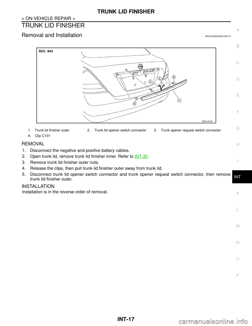
REMOVAL
1. Disconnect the negative and positive battery cables.
2. Open trunk lid, remove trunk lid finisher inner. Refer to INT-35
.
3. Remove trunk lid finisher outer nuts.
4. Release the clips, then pull trunk lid finisher outer away from trunk lid.
5. Disconnect trunk lid opener switch connector and trunk opener request switch connector, then remove
trunk lid finisher outer.
INSTALLATION
Installation is in the reverse order of removal.
1. Trunk lid finisher outer 2. Trunk lid opener switch connector 3. Trunk opener request switch connector
A. Clip C101
WIIA1413E
Page 3714 of 5883
TRUNK ROOM TRIM & TRUNK LID FINISHER
INT-35
< ON-VEHICLE REPAIR >
C
D
E
F
G
H
I
K
L
MA
B
INT
N
O
P
TRUNK ROOM TRIM & TRUNK LID FINISHER
Removal and InstallationINFOID:0000000001329058
REMOVAL
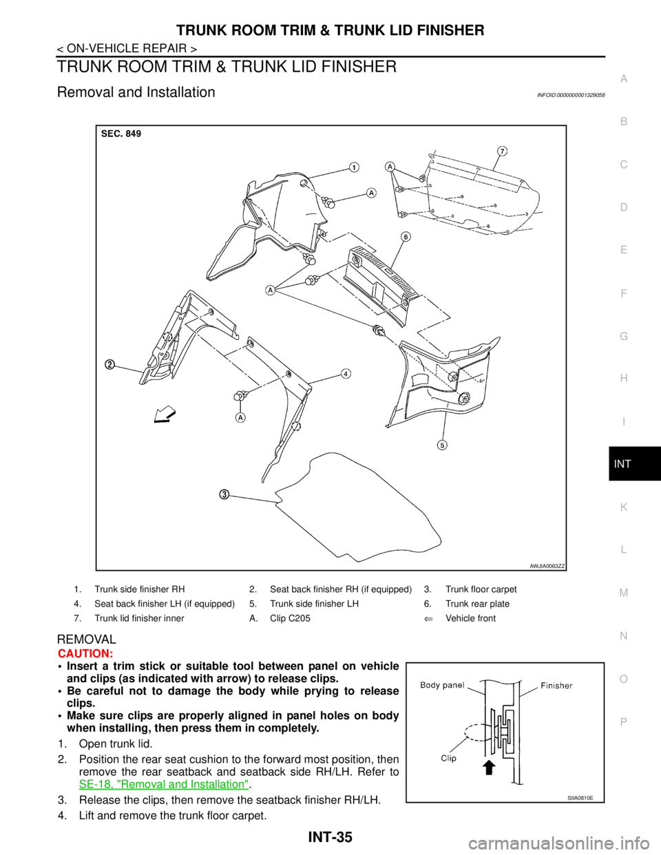
CAUTION:
Insert a trim stick or suitable tool between panel on vehicle
and clips (as indicated with arrow) to release clips.
Be careful not to damage the body while prying to release
clips.
Make sure clips are properly aligned in panel holes on body
when installing, then press them in completely.
1. Open trunk lid.
2. Position the rear seat cushion to the forward most position, then
remove the rear seatback and seatback side RH/LH. Refer to
SE-18, "
Removal and Installation".
3. Release the clips, then remove the seatback finisher RH/LH.
4. Lift and remove the trunk floor carpet.
1. Trunk side finisher RH 2. Seat back finisher RH (if equipped) 3. Trunk floor carpet
4. Seat back finisher LH (if equipped) 5. Trunk side finisher LH 6. Trunk rear plate
7. Trunk lid finisher inner A. Clip C205⇐Vehicle front
AWJIA0063ZZ
SIIA0810E
Page 3715 of 5883

INT-36
< ON-VEHICLE REPAIR >
TRUNK ROOM TRIM & TRUNK LID FINISHER
5. Release the clips, then remove the trunk rear plate.
6. Release the clips, then remove the trunk side finisher RH/LH.
7. Release the clips and remove the trunk lid finisher inner from the trunk lid.
INSTALLATION
Installation is in the reverse order of removal.
Page 3721 of 5883

IP-6
< SERVICE INFORMATION >
SQUEAK AND RATTLE TROUBLE DIAGNOSES
Used in place of UHMW tape that will be visible or not fit.
Note: Will only last a few months.
SILICONE SPRAY
Use when grease cannot be applied.
DUCT TAPE
Use to eliminate movement.
CONFIRM THE REPAIR
Confirm that the cause of a noise is repaired by test driving the vehicle. Operate the vehicle under the same
conditions as when the noise originally occurred. Refer to the notes on the Diagnostic Worksheet.
Generic Squeak and Rattle TroubleshootingINFOID:0000000001523315
Refer to Table of Contents for specific component removal and installation information.
INSTRUMENT PANEL
Most incidents are caused by contact and movement between:
1. The cluster lid A and instrument panel
2. Acrylic lens and combination meter housing
3. Instrument panel to front pillar garnish
4. Instrument panel to windshield
5. Instrument panel mounting pins
6. Wiring harnesses behind the combination meter
7. A/C defroster duct and duct joint
These incidents can usually be located by tapping or moving the components to duplicate the noise or by
pressing on the components while driving to stop the noise. Most of these incidents can be repaired by apply-
ing felt cloth tape or silicone spray (in hard to reach areas). Urethane pads can be used to insulate wiring har-
ness.
CAUTION:
Do not use silicone spray to isolate a squeak or rattle. If you saturate the area with silicone, you will
not be able to recheck the repair.
CENTER CONSOLE
Components to pay attention to include:
1. Shifter assembly cover to finisher
2. A/C control unit and cluster lid C
3. Wiring harnesses behind audio and A/C control unit
The instrument panel repair and isolation procedures also apply to the center console.
DOORS
Pay attention to the:
1. Finisher and inner panel making a slapping noise
2. Inside handle escutcheon to door finisher
3. Wiring harnesses tapping
4. Door striker out of alignment causing a popping noise on starts and stops
Tapping or moving the components or pressing on them while driving to duplicate the conditions can isolate
many of these incidents. You can usually insulate the areas with felt cloth tape or insulator foam blocks from
the Squeak and Rattle Kit to repair the noise.
TRUNK
Trunk noises are often caused by a loose jack or loose items put into the trunk by the owner.
In addition look for:
1. Trunk lid bumpers out of adjustment
2. Trunk lid striker out of adjustment
3. The trunk lid torsion bars knocking together
4. A loose license plate or bracket
Page 3774 of 5883
![NISSAN TIIDA 2007 Service Repair Manual LAN-34
< FUNCTION DIAGNOSIS >[CAN]
CAN COMMUNICATION SYSTEM
Buzzer output signalTR
TR
Day time running light request signal T R
Door lock/unlock signal T R
Door switch signal T R R
Front fog light req NISSAN TIIDA 2007 Service Repair Manual LAN-34
< FUNCTION DIAGNOSIS >[CAN]
CAN COMMUNICATION SYSTEM
Buzzer output signalTR
TR
Day time running light request signal T R
Door lock/unlock signal T R
Door switch signal T R R
Front fog light req](/manual-img/5/57395/w960_57395-3773.png)
LAN-34
< FUNCTION DIAGNOSIS >[CAN]
CAN COMMUNICATION SYSTEM
Buzzer output signalTR
TR
Day time running light request signal T R
Door lock/unlock signal T R
Door switch signal T R R
Front fog light request signal T R R
Front wiper request signal T R
High beam request signal T R R
Ignition switch signal T R
Low beam request signal T R
Position light request signal T R R
Rear fog lamp status signal T R
Rear window defogger switch signal T R
Sleep wake up signalTRR R
RT
RT
RT
Trunk open/close status signal T R
Turn indicator signal T R
EPS operation signal
*3RT
EPS warning lamp signal T R
Door lock/unlock trunk open request signal R T
Hazard request signal R T
Key warning lamp signal T R
LOCK warning lamp signal T R
Distance to empty signal T R
Fuel level sensor signal R T
Overdrive control signal T R
P/N renge signal T R
Stop lamp switch signalTR
RT
Vehicle speed signalRRRRT R
RRR TR
Steering angle sensor signal
*1TR
ABS warning lamp signal R T
Brake warning lamp signal R T
ESP OFF indicator lamp signal
*1RT
A/T check indicator signal R T
A/T self-diagnosis signal R T
OD OFF indicator lamp signal R T
Output shaft revolution signal R T
Shift position indicator signal R
R
*1T Signal name/Connecting unit
ECM
BCM
EPS
I-KEY
M&A
STRG
AV
ABS
TCM
IPDM-E
Page 4246 of 5883
MA-6
< ON-VEHICLE MAINTENANCE >
GENERAL MAINTENANCE
ON-VEHICLE MAINTENANCE
GENERAL MAINTENANCE
General MaintenanceINFOID:0000000001277597
General maintenance includes those items which should be checked during the normal day-to-day operation
of the vehicle. They are essential if the vehicle is to continue operating properly. The owners can perform the
checks and inspections themselves or they can have their NISSAN dealers do them for a nominal charge.
OUTSIDE THE VEHICLE
The maintenance items listed here should be performed from time to time, unless otherwise specified.
INSIDE THE VEHICLE
The maintenance items listed here should be checked on a regular basis, such as when performing periodic maintenance, cleaning the vehicle,
etc.
UNDER THE HOOD AND VEHICLE
The maintenance items listed here should be checked periodically e.g. each time you check the engine oil or refuel.
Item Reference page
TiresCheck the pressure with a gauge periodically when at a service station, including
the spare, and adjust to the specified pressure if necessary. Check carefully for
damage, cuts or excessive wear.WT-7, "
Tire"
Windshield wiper
bladesCheck for cracks or wear if not functioning correctly. —
Doors and engine
hoodCheck that all doors, the engine hood, the trunk lid and back door operate prop-
erly. Also ensure that all latches lock securely. Lubricate if necessary. Make sure
that the secondary latch keeps the hood from opening when the primary latch is
released.
When driving in areas using road salt or other corrosive materials, check for lu-
brication frequently.MA-57, "
Lubricating
Locks, Hinges and Hood
Latch"
Tire rotationTires should be rotated every 10,000 km (6,000 miles) for 2WD models and every
5,000 km (3,000 miles) for 4WD models.MA-53
Item Reference page
LampsMake sure that the headlamps, stop lamps, tail lamps, turn signal lamps, and oth-
er lamps are all operating properly and installed securely. Also check headlamp
aim.—
Warning lamps and
chimesMake sure that all warning lamps and buzzers/chimes are operating properly. —
Steering wheelCheck that it has the specified play.
Check for changes in the steering conditions, such as excessive free play, hard
steering or strange noises.
Free play: Less than 35 mm (1.38 in)—
Seat beltsCheck that all parts of the seat belt system (e.g. buckles, anchors, adjusters and
retractors) operate properly and smoothly, and are installed securely. Check the
belt webbing for cuts, fraying, wear or damage.MA-57
Item Reference page
Windshield washer
fluidCheck that there is adequate fluid in the tank. —
Engine coolant levelCheck the coolant level when the engine is cold.MA-23
(HR)
MA-31
(MR)
MA-42
(K9K)
Engine oil levelCheck the level after parking the vehicle on a level spot and turning off the en-
gine.LU-6
(HR)
LU-15
(MR)
LU-26
(K9K)
Brake and clutch fluid
levelsMake sure that the brake and clutch fluid levels are between the “MAX” and “MIN”
lines on the reservoir.MA-50
,
MA-54
BatteryCheck the fluid level in each cell. It should be between the “MAX” and “MIN” lines. —
Page 4366 of 5883
MWI
BCM (BODY CONTROL MODULE)
MWI-59
< ECU DIAGNOSIS >
C
D
E
F
G
H
I
J
K
L
MB A
O
P
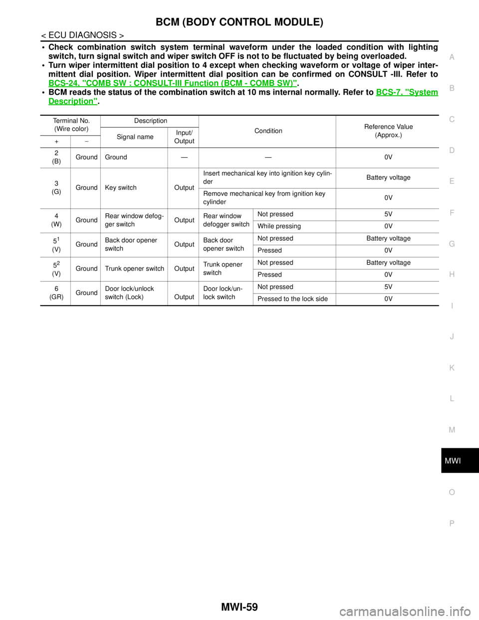
Check combination switch system terminal waveform under the loaded condition with lighting
switch, turn signal switch and wiper switch OFF is not to be fluctuated by being overloaded.
Turn wiper intermittent dial position to 4 except when checking waveform or voltage of wiper inter-
mittent dial position. Wiper intermittent dial position can be confirmed on CONSULT -III. Refer to
BCS-24, "
COMB SW : CONSULT-III Function (BCM - COMB SW)".
BCM reads the status of the combination switch at 10 ms internal normally. Refer to BCS-7, "
System
Description".
Terminal No.
(Wire color)Description
ConditionReference Value
(Approx.)
Signal nameInput/
Output +−
2
(B)Ground Ground — — 0V
3
(G)Ground Key switch OutputInsert mechanical key into ignition key cylin-
derBattery voltage
Remove mechanical key from ignition key
cylinder0V
4
(W)GroundRear window defog-
ger switchOutputRear window
defogger switchNot pressed 5V
While pressing 0V
5
1
(V)GroundBack door opener
switchOutputBack door
opener switchNot pressed Battery voltage
Pressed 0V
5
2
(V)Ground Trunk opener switch OutputTrunk opener
switchNot pressed Battery voltage
Pressed 0V
6
(GR)GroundDoor lock/unlock
switch (Lock) OutputDoor lock/un-
lock switchNot pressed 5V
Pressed to the lock side 0V