Page 3657 of 5883

INL-6
< FUNCTION DIAGNOSIS >
INTERIOR ROOM LAMP CONTROL SYSTEM
a signal is received from an Intelligent Key or main power window and door lock/unlock switch, or when the
front door LH lock assembly (key cylinder switch) is locked or unlocked
a door is opened or closed
the Intelligent Key is removed from or inserted into the key slot.
The Interior lamp battery saver control time period can be changed with the function setting of CONSULT-III.
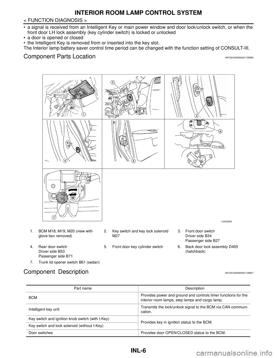
Component Parts LocationINFOID:0000000001728856
Component DescriptionINFOID:0000000001728857
1. BCM M18, M19, M20 (view with
glove box removed)2. Key switch and key lock solenoid
M273. Front door switch
Driver side B34
Passenger side B27
4. Rear door switch
Driver side B53
Passenger side B715. Front door key cylinder switch 6. Back door lock assembly D405
(hatchback)
7. Trunk lid opener switch B61 (sedan)
LIIA2942E
Part name Description
BCMProvides power and ground and controls timer functions for the
interior room lamps, step lamps and cargo lamp.
Intelligent key unitTransmits the lock/unlock signal to the BCM via CAN communi-
cation.
Key switch and ignition knob switch (with I-Key)
Provides key in ignition status to the BCM.
Key switch and lock solenoid (without I-Key)
Door switches Provides door OPEN/CLOSED status to the BCM.
Page 3658 of 5883
INTERIOR ROOM LAMP CONTROL SYSTEM
INL-7
< FUNCTION DIAGNOSIS >
C
D
E
F
G
H
I
J
K
MA
B
INL
N
O
P
Back door lock assembly (hatchback)
Provides back door OPEN/CLOSED status to the BCM.
Back door opener switch (hatchback)
Trunk lid opener switch (sedan) Provides trunk lid OPEN/CLOSED status to the BCM.
Main power window and door lock/unlock switch [front door lock
assembly LH (key cylinder switch)]. Provides door lock/unlock position switch LH status to the BCM.
Page 3666 of 5883

INTERIOR ROOM LAMP POWER SUPPLY CIRCUIT
INL-15
< COMPONENT DIAGNOSIS >
C
D
E
F
G
H
I
J
K
MA
B
INL
N
O
P
INTERIOR ROOM LAMP POWER SUPPLY CIRCUIT
DescriptionINFOID:0000000001728870
Provides the interior room lamp power supply. Also cuts the power supply when the interior room lamp battery
saver activating.
Component Function CheckINFOID:0000000001728871
1.CHECK INTERIOR ROOM LAMP POWER SUPPLY FUNCTION
CONSULT-III ACTIVE TEST
1. Turn ignition switch ON.
2. Turn each interior room lamp ON.
- Map lamp
- Interior room lamp
- Vanity mirror lamp (if equipped)
- Trunk room lamp
3. Select “BATTERY SAVER” of BCM (BATTERY SAVER) active test item.
4. With operating the test items, check that each interior room lamp is turned ON/OFF.
Is the interior room lamp turned ON/OFF?
YES >> Interior room lamp power supply circuit is normal.
NO >> Refer to INL-15, "
Diagnosis Procedure".
Diagnosis ProcedureINFOID:0000000001728872
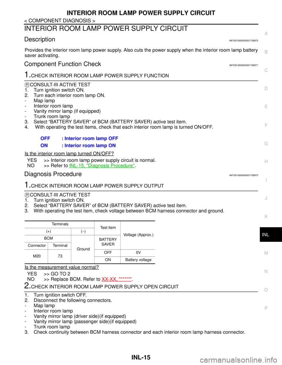
1.CHECK INTERIOR ROOM LAMP POWER SUPPLY OUTPUT
CONSULT-III ACTIVE TEST
1. Turn ignition switch ON.
2. Select “BATTERY SAVER” of BCM (BATTERY SAVER) active test item.
3. With operating the test item, check voltage between BCM harness connector and ground.
Is the measurement value normal?
YES >> GO TO 2
NO >> Replace BCM. Refer to XX-XX, "*****"
.
2.CHECK INTERIOR ROOM LAMP POWER SUPPLY OPEN CIRCUIT
1. Turn ignition switch OFF.
2. Disconnect the following connectors.
- Map lamp
- Interior room lamp
- Vanity mirror lamp (driver side)(if equipped)
- Vanity mirror lamp (passenger side)(if equipped)
- Trunk room lamp
3. Check continuity between BCM harness connector and each interior room lamp harness connector.OFF : Interior room lamp OFF
ON : Interior room lamp ON
Te r m i n a l s
Te s t i t e m
Voltage (Approx.) (+) (−)
BCM
GroundBATTERY
SAVER
Connector Terminal
M20 73OFF 0V
ON Battery voltage
Page 3667 of 5883
INL-16
< COMPONENT DIAGNOSIS >
INTERIOR ROOM LAMP POWER SUPPLY CIRCUIT
Does continuity exist?
YES >> GO TO 3
NO >> Repair the harnesses or connectors.
3.CHECK INTERIOR ROOM LAMP POWER SUPPLY SHORT CIRCUIT
Check continuity between BCM harness connector and ground.
Does continuity exist?
YES >> Repair the harnesses or connectors.
NO >> Check that each interior room lamp has no internal short circuit.
BCM Each interior room lamp
Continu-
ity Connec-
torTerminal Connector Terminal
M20 73Map lamp R2 4
Existed Interior room lamp R7 3
Vanity mirror lamp
RHR10 1
Vanity mirror lamp
LHR9 1
Trunk room lamp B36 1
BCM
GroundContinuity
Connector Terminal
M20 73 Not existed
Page 3674 of 5883

INTERIOR LIGHTING SYSTEM SYMPTOMS
INL-23
< SYMPTOM DIAGNOSIS >
C
D
E
F
G
H
I
J
K
MA
B
INL
N
O
P
SYMPTOM DIAGNOSIS
INTERIOR LIGHTING SYSTEM SYMPTOMS
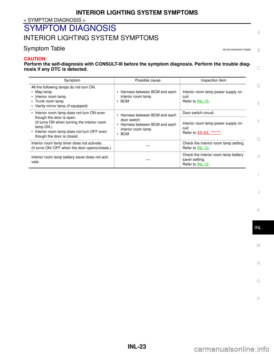
Symptom TableINFOID:0000000001728883
CAUTION:
Perform the self-diagnosis with CONSULT-III before the symptom diagnosis. Perform the trouble diag-
nosis if any DTC is detected.
Symptom Possible cause Inspection item
All the following lamps do not turn ON.
Map lamp
Interior room lamp
Trunk room lamp
Vanity mirror lamp (if equipped) Harness between BCM and each
interior room lamp
BCMInterior room lamp power supply cir-
cuit
Refer to INL-15
.
Interior room lamp does not turn ON even
though the door is open.
(It turns ON when turning the interior room
lamp ON.)
Interior room lamp does not turn OFF even
though the door is closed. Harness between BCM and each
door switch
Harness between BCM and each
interior room lamp
BCMDoor switch circuit.
Interior room lamp power supply cir-
cuit
Refer to XX-XX, "*****"
.
Interior room lamp timer does not activate.
(It turns ON/ OFF when the door opens/closes.)—Check the interior room lamp setting.
Refer to INL-10
.
Interior room lamp battery saver does not acti-
vate.—Check the interior room lamp battery
saver setting.
Refer to INL-12
.
Page 3678 of 5883

INTERIOR ROOM LAMP
INL-27
< ON-VEHICLE REPAIR >
C
D
E
F
G
H
I
J
K
MA
B
INL
N
O
P
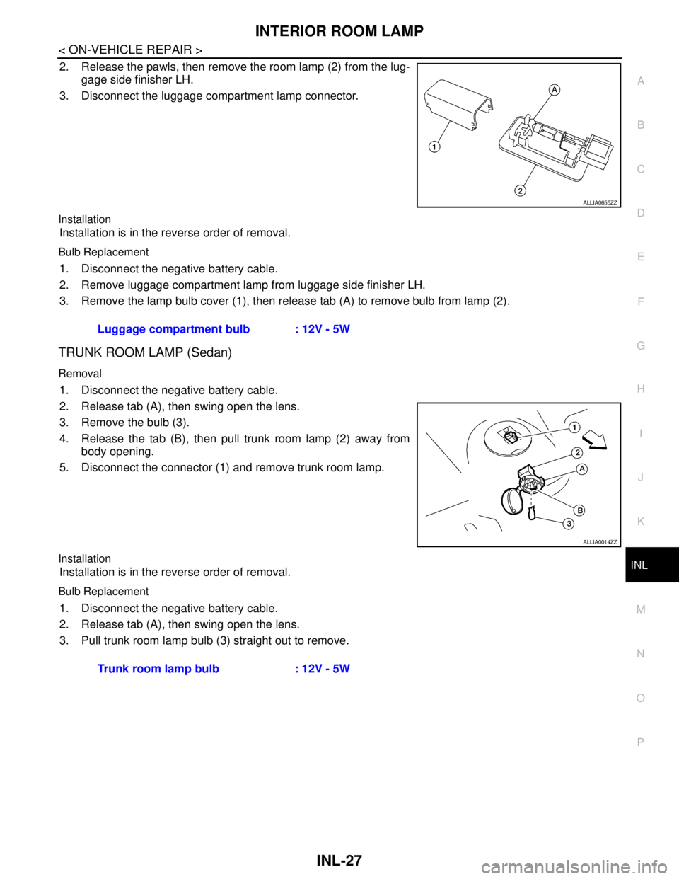
2. Release the pawls, then remove the room lamp (2) from the lug-
gage side finisher LH.
3. Disconnect the luggage compartment lamp connector.
Installation
Installation is in the reverse order of removal.
Bulb Replacement
1. Disconnect the negative battery cable.
2. Remove luggage compartment lamp from luggage side finisher LH.
3. Remove the lamp bulb cover (1), then release tab (A) to remove bulb from lamp (2).
TRUNK ROOM LAMP (Sedan)
Removal
1. Disconnect the negative battery cable.
2. Release tab (A), then swing open the lens.
3. Remove the bulb (3).
4. Release the tab (B), then pull trunk room lamp (2) away from
body opening.
5. Disconnect the connector (1) and remove trunk room lamp.
Installation
Installation is in the reverse order of removal.
Bulb Replacement
1. Disconnect the negative battery cable.
2. Release tab (A), then swing open the lens.
3. Pull trunk room lamp bulb (3) straight out to remove.
ALLIA0655ZZ
Luggage compartment bulb : 12V - 5W
ALLIA0014ZZ
Trunk room lamp bulb : 12V - 5W
Page 3679 of 5883
INL-28
< SERVICE DATA AND SPECIFICATIONS (SDS)
SERVICE DATA AND SPECIFICATIONS (SDS)
SERVICE DATA AND SPECIFICATIONS (SDS)
SERVICE DATA AND SPECIFICATIONS (SDS)
Bulb SpecificationsINFOID:0000000001726700
* Always check with the Parts Department for the latest parts information.Item Type Wattage (W) Bulb No.*
Map lamp Cylinder 8 AL54
Vanity mirror lamp (if equipped) Cylinder 2 -
Glove box lamp (if equipped) Wedge 1.4 -
Room lamp Cylinder 8 -
Luggage compartment lamp (Hatchback) Cylinder 5 B5Y
Trunk room lamp (Sedan) Wedge 5 158
Page 3680 of 5883

INT-1
BODY INTERIOR
C
D
E
F
G
H
I
K
L
M
SECTION INT
A
B
INT
N
O
P
CONTENTS
INTERIOR
PRECAUTION ...............................................2
PRECAUTIONS ...................................................2
Precaution for Supplemental Restraint System
(SRS) "AIR BAG" and "SEAT BELT PRE-TEN-
SIONER" ...................................................................
2
Precaution .................................................................2
PREPARATION ............................................3
PREPARATION ...................................................3
Commercial Service Tool ..........................................3
CLIP AND FASTENER ........................................4
Description ................................................................4
SQUEAK AND RATTLE TROUBLE DIAGNO-
SIS .......................................................................
7
Work Flow .................................................................7
Generic Squeak and Rattle Troubleshooting ............9
Diagnostic Worksheet .............................................11
ON-VEHICLE REPAIR .................................13
DOOR FINISHER ...............................................13
Removal and Installation .........................................13
TRUNK LID FINISHER ......................................17
Removal and Installation .........................................17
BACK DOOR TRIM ...........................................18
Removal and Installation .........................................18
BODY SIDE TRIM .............................................19
Component ..............................................................19
Removal and Installation .........................................20
LUGGAGE FLOOR TRIM .................................24
Removal and Installation .........................................24
REAR PARCEL SHELF FINISHER ..................26
Removal and Installation .........................................26
FLOOR TRIM ....................................................27
Removal and Installation .........................................27
HEADLINING ....................................................29
Component ..............................................................29
Removal and Installation - Hatchback .....................31
Removal and Installation - Sedan ............................33
TRUNK ROOM TRIM & TRUNK LID FINISH-
ER ......................................................................
35
Removal and Installation .........................................35