2007 NISSAN TIIDA boot
[x] Cancel search: bootPage 3140 of 5883
FAX-6
< ON-VEHICLE MAINTENANCE >
FRONT DRIVE SHAFT
FRONT DRIVE SHAFT
On-Vehicle Inspection and ServiceINFOID:0000000001716790
Check drive shaft mounting point and joint for looseness and other damage.
Check boot for cracks and other damage.
Replace or repair components as necessary. Refer to FAX-10, "
Removal and Installation (Left Side)" , FA X - 11 ,
"Removal and Installation (Right Side)" , FAX-14, "Disassembly and Assembly (Left Side)" or FAX-19, "Disas-
sembly and Assembly (Right Side)" .
CAUTION:
Replace entire drive shaft assembly when noise or vibration occur from drive shaft.
Page 3142 of 5883
FAX-8
< REMOVAL AND INSTALLATION >
FRONT WHEEL HUB AND KNUCKLE
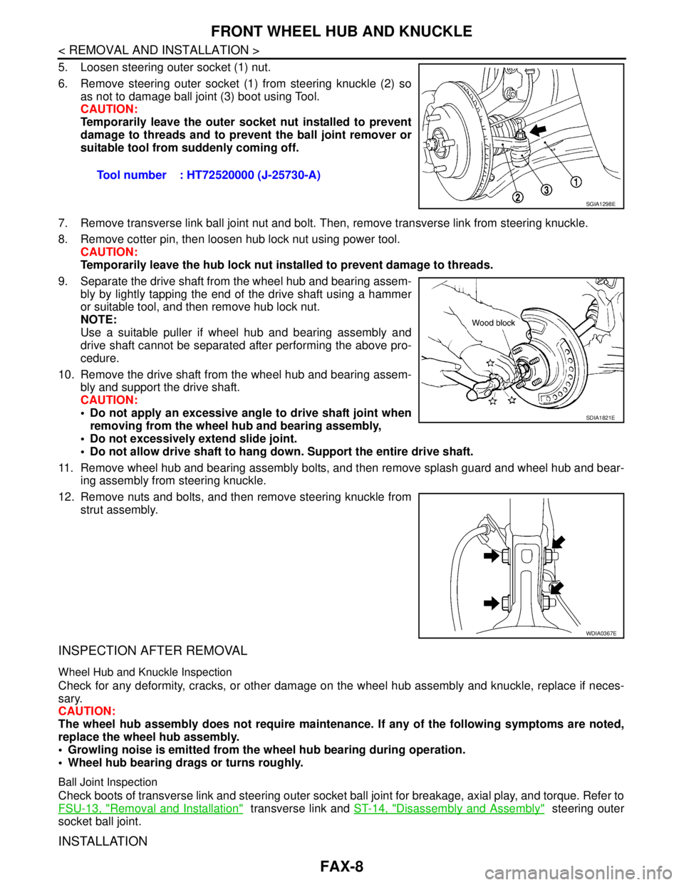
5. Loosen steering outer socket (1) nut.
6. Remove steering outer socket (1) from steering knuckle (2) so
as not to damage ball joint (3) boot using Tool.
CAUTION:
Temporarily leave the outer socket nut installed to prevent
damage to threads and to prevent the ball joint remover or
suitable tool from suddenly coming off.
7. Remove transverse link ball joint nut and bolt. Then, remove transverse link from steering knuckle.
8. Remove cotter pin, then loosen hub lock nut using power tool.
CAUTION:
Temporarily leave the hub lock nut installed to prevent damage to threads.
9. Separate the drive shaft from the wheel hub and bearing assem-
bly by lightly tapping the end of the drive shaft using a hammer
or suitable tool, and then remove hub lock nut.
NOTE:
Use a suitable puller if wheel hub and bearing assembly and
drive shaft cannot be separated after performing the above pro-
cedure.
10. Remove the drive shaft from the wheel hub and bearing assem-
bly and support the drive shaft.
CAUTION:
Do not apply an excessive angle to drive shaft joint when
removing from the wheel hub and bearing assembly,
Do not excessively extend slide joint.
Do not allow drive shaft to hang down. Support the entire drive shaft.
11. Remove wheel hub and bearing assembly bolts, and then remove splash guard and wheel hub and bear-
ing assembly from steering knuckle.
12. Remove nuts and bolts, and then remove steering knuckle from
strut assembly.
INSPECTION AFTER REMOVAL
Wheel Hub and Knuckle Inspection
Check for any deformity, cracks, or other damage on the wheel hub assembly and knuckle, replace if neces-
sary.
CAUTION:
The wheel hub assembly does not require maintenance. If any of the following symptoms are noted,
replace the wheel hub assembly.
Growling noise is emitted from the wheel hub bearing during operation.
Wheel hub bearing drags or turns roughly.
Ball Joint Inspection
Check boots of transverse link and steering outer socket ball joint for breakage, axial play, and torque. Refer to
FSU-13, "
Removal and Installation" transverse link and ST-14, "Disassembly and Assembly" steering outer
socket ball joint.
INSTALLATION
Tool number : HT72520000 (J-25730-A)
SGIA1298E
SDIA1821E
WDIA0367E
Page 3145 of 5883
FRONT DRIVE SHAFT
FAX-11
< REMOVAL AND INSTALLATION >
C
E
F
G
H
I
J
K
L
MA
B
FA X
N
O
P
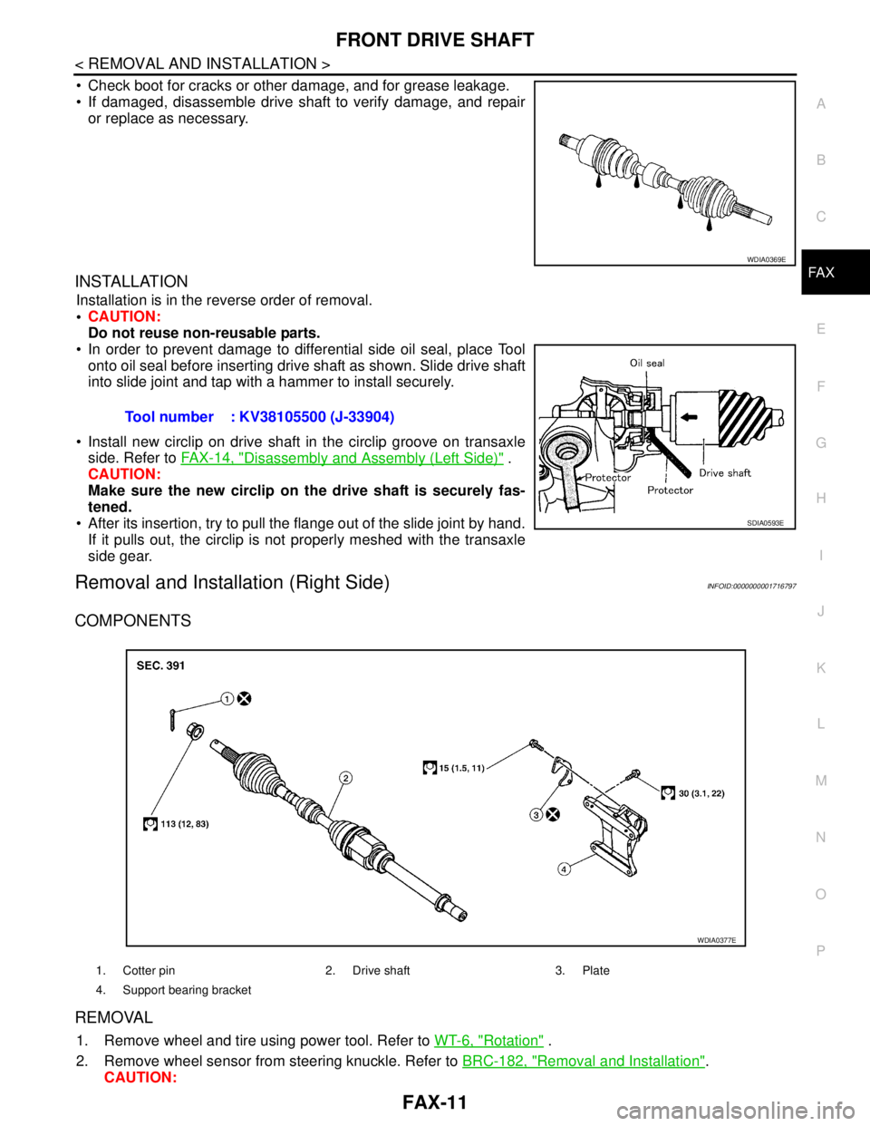
Check boot for cracks or other damage, and for grease leakage.
If damaged, disassemble drive shaft to verify damage, and repair
or replace as necessary.
INSTALLATION
Installation is in the reverse order of removal.
CAUTION:
Do not reuse non-reusable parts.
In order to prevent damage to differential side oil seal, place Tool
onto oil seal before inserting drive shaft as shown. Slide drive shaft
into slide joint and tap with a hammer to install securely.
Install new circlip on drive shaft in the circlip groove on transaxle
side. Refer to FAX-14, "
Disassembly and Assembly (Left Side)" .
CAUTION:
Make sure the new circlip on the drive shaft is securely fas-
tened.
After its insertion, try to pull the flange out of the slide joint by hand.
If it pulls out, the circlip is not properly meshed with the transaxle
side gear.
Removal and Installation (Right Side)INFOID:0000000001716797
COMPONENTS
REMOVAL
1. Remove wheel and tire using power tool. Refer to WT-6, "Rotation" .
2. Remove wheel sensor from steering knuckle. Refer to BRC-182, "
Removal and Installation".
CAUTION:
WDIA0369E
Tool number : KV38105500 (J-33904)
SDIA0593E
1. Cotter pin 2. Drive shaft 3. Plate
4. Support bearing bracket
WDIA0377E
Page 3146 of 5883
FAX-12
< REMOVAL AND INSTALLATION >
FRONT DRIVE SHAFT
Do not pull on wheel sensor harness.
3. Remove transverse link ball joint nut and bolt. Then, remove transverse link from steering knuckle.
4. Remove cotter pin, then loosen hub lock nut using power tool.
CAUTION:
Temporarily leave the hub lock nut installed to prevent damage to threads.
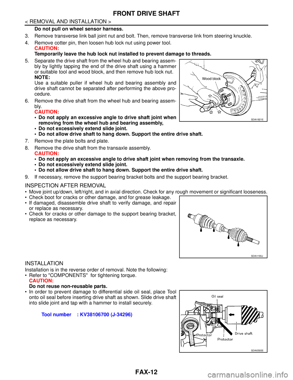
5. Separate the drive shaft from the wheel hub and bearing assem-
bly by lightly tapping the end of the drive shaft using a hammer
or suitable tool and wood block, and then remove hub lock nut.
NOTE:
Use a suitable puller if wheel hub and bearing assembly and
drive shaft cannot be separated after performing the above pro-
cedure.
6. Remove the drive shaft from the wheel hub and bearing assem-
bly.
CAUTION:
Do not apply an excessive angle to drive shaft joint when
removing from the wheel hub and bearing assembly,
Do not excessively extend slide joint.
Do not allow drive shaft to hang down. Support the entire drive shaft.
7. Remove the plate bolts and plate.
8. Remove the drive shaft from the transaxle assembly.
CAUTION:
Do not apply an excessive angle to drive shaft joint when removing from the transaxle.
Do not excessively extend slide joint.
Do not allow drive shaft to hang down. Support the entire drive shaft.
9. If necessary, remove the support bearing bracket bolts and the support bearing bracket.
INSPECTION AFTER REMOVAL
Move joint up/down, left/right, and in axial direction. Check for any rough movement or significant looseness.
Check boot for cracks or other damage, and for grease leakage.
If damaged, disassemble drive shaft to verify damage, and repair
or replace as necessary.
Check for cracks or other damage to the support bearing bracket,
replace as necessary.
INSTALLATION
Installation is in the reverse order of removal. Note the following:
Refer to "COMPONENTS" for tightening torque.
CAUTION:
Do not reuse non-reusable parts.
In order to prevent damage to differential side oil seal, place Tool
onto oil seal before inserting drive shaft as shown. Slide drive shaft
into slide joint and tap with a hammer to install securely.
SDIA1821E
SDIA1190J
Tool number : KV38106700 (J-34296)
SDIA0593E
Page 3148 of 5883
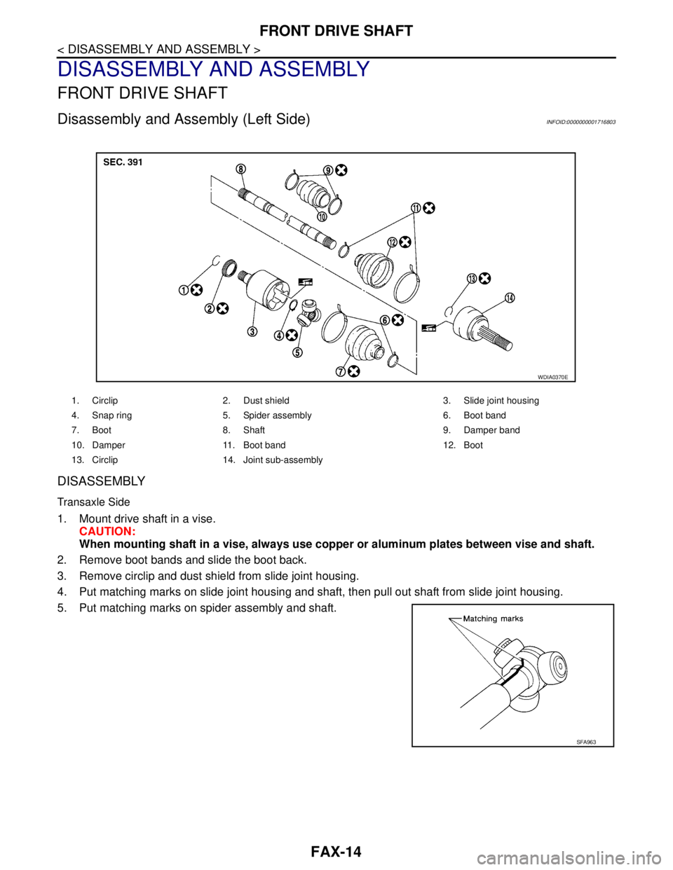
FAX-14
< DISASSEMBLY AND ASSEMBLY >
FRONT DRIVE SHAFT
DISASSEMBLY AND ASSEMBLY
FRONT DRIVE SHAFT
Disassembly and Assembly (Left Side)INFOID:0000000001716803
DISASSEMBLY
Transaxle Side
1. Mount drive shaft in a vise.
CAUTION:
When mounting shaft in a vise, always use copper or aluminum plates between vise and shaft.
2. Remove boot bands and slide the boot back.
3. Remove circlip and dust shield from slide joint housing.
4. Put matching marks on slide joint housing and shaft, then pull out shaft from slide joint housing.
5. Put matching marks on spider assembly and shaft.
1. Circlip 2. Dust shield 3. Slide joint housing
4. Snap ring 5. Spider assembly 6. Boot band
7. Boot 8. Shaft 9. Damper band
10. Damper 11. Boot band 12. Boot
13. Circlip 14. Joint sub-assembly
WDIA0370E
SFA963
Page 3149 of 5883
FRONT DRIVE SHAFT
FAX-15
< DISASSEMBLY AND ASSEMBLY >
C
E
F
G
H
I
J
K
L
MA
B
FA X
N
O
P
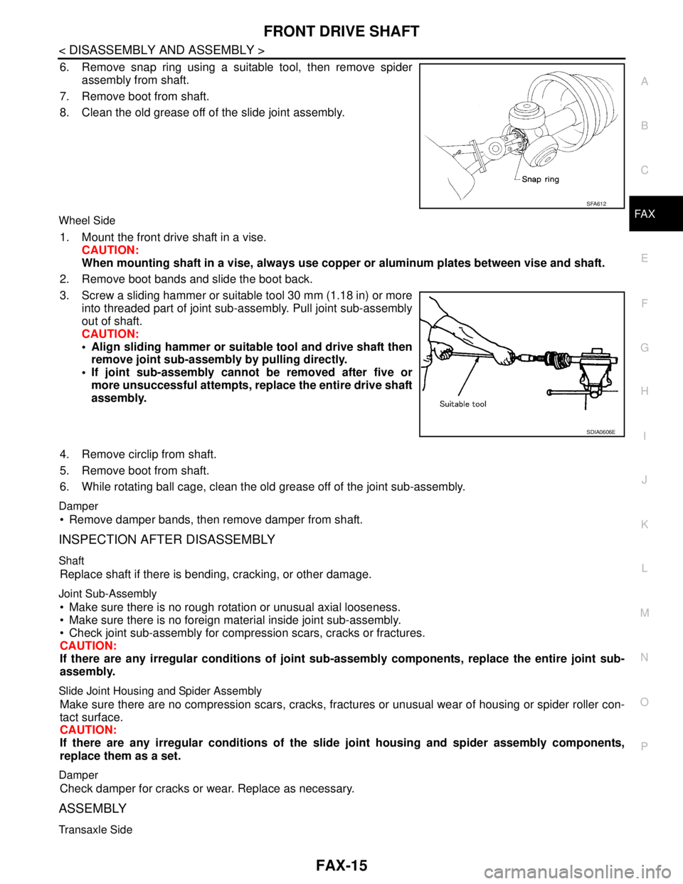
6. Remove snap ring using a suitable tool, then remove spider
assembly from shaft.
7. Remove boot from shaft.
8. Clean the old grease off of the slide joint assembly.
Wheel Side
1. Mount the front drive shaft in a vise.
CAUTION:
When mounting shaft in a vise, always use copper or aluminum plates between vise and shaft.
2. Remove boot bands and slide the boot back.
3. Screw a sliding hammer or suitable tool 30 mm (1.18 in) or more
into threaded part of joint sub-assembly. Pull joint sub-assembly
out of shaft.
CAUTION:
Align sliding hammer or suitable tool and drive shaft then
remove joint sub-assembly by pulling directly.
If joint sub-assembly cannot be removed after five or
more unsuccessful attempts, replace the entire drive shaft
assembly.
4. Remove circlip from shaft.
5. Remove boot from shaft.
6. While rotating ball cage, clean the old grease off of the joint sub-assembly.
Damper
Remove damper bands, then remove damper from shaft.
INSPECTION AFTER DISASSEMBLY
Shaft
Replace shaft if there is bending, cracking, or other damage.
Joint Sub-Assembly
Make sure there is no rough rotation or unusual axial looseness.
Make sure there is no foreign material inside joint sub-assembly.
Check joint sub-assembly for compression scars, cracks or fractures.
CAUTION:
If there are any irregular conditions of joint sub-assembly components, replace the entire joint sub-
assembly.
Slide Joint Housing and Spider Assembly
Make sure there are no compression scars, cracks, fractures or unusual wear of housing or spider roller con-
tact surface.
CAUTION:
If there are any irregular conditions of the slide joint housing and spider assembly components,
replace them as a set.
Damper
Check damper for cracks or wear. Replace as necessary.
ASSEMBLY
Transaxle Side
SFA612
SDIA0606E
Page 3150 of 5883
FAX-16
< DISASSEMBLY AND ASSEMBLY >
FRONT DRIVE SHAFT
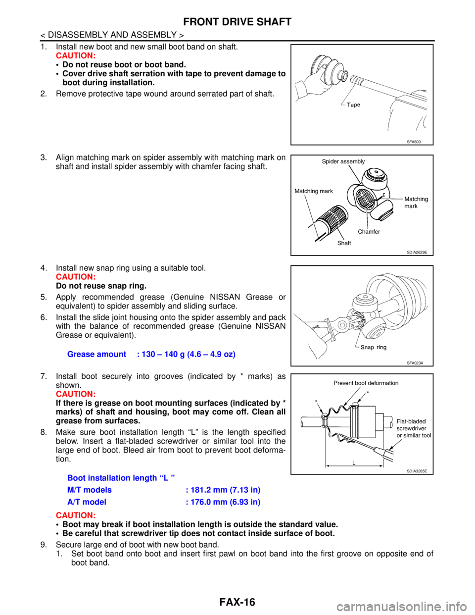
1. Install new boot and new small boot band on shaft.
CAUTION:
Do not reuse boot or boot band.
Cover drive shaft serration with tape to prevent damage to
boot during installation.
2. Remove protective tape wound around serrated part of shaft.
3. Align matching mark on spider assembly with matching mark on
shaft and install spider assembly with chamfer facing shaft.
4. Install new snap ring using a suitable tool.
CAUTION:
Do not reuse snap ring.
5. Apply recommended grease (Genuine NISSAN Grease or
equivalent) to spider assembly and sliding surface.
6. Install the slide joint housing onto the spider assembly and pack
with the balance of recommended grease (Genuine NISSAN
Grease or equivalent).
7. Install boot securely into grooves (indicated by * marks) as
shown.
CAUTION:
If there is grease on boot mounting surfaces (indicated by *
marks) of shaft and housing, boot may come off. Clean all
grease from surfaces.
8. Make sure boot installation length “L” is the length specified
below. Insert a flat-bladed screwdriver or similar tool into the
large end of boot. Bleed air from boot to prevent boot deforma-
tion.
CAUTION:
Boot may break if boot installation length is outside the standard value.
Be careful that screwdriver tip does not contact inside surface of boot.
9. Secure large end of boot with new boot band.
1. Set boot band onto boot and insert first pawl on boot band into the first groove on opposite end of
boot band.
SFA800
SDIA2629E
Grease amount : 130 – 140 g (4.6 – 4.9 oz) SFA023A
Boot installation length “L ”
M/T models : 181.2 mm (7.13 in)
A/T model : 176.0 mm (6.93 in)
SDIA3285E
Page 3151 of 5883
FRONT DRIVE SHAFT
FAX-17
< DISASSEMBLY AND ASSEMBLY >
C
E
F
G
H
I
J
K
L
MA
B
FA X
N
O
P
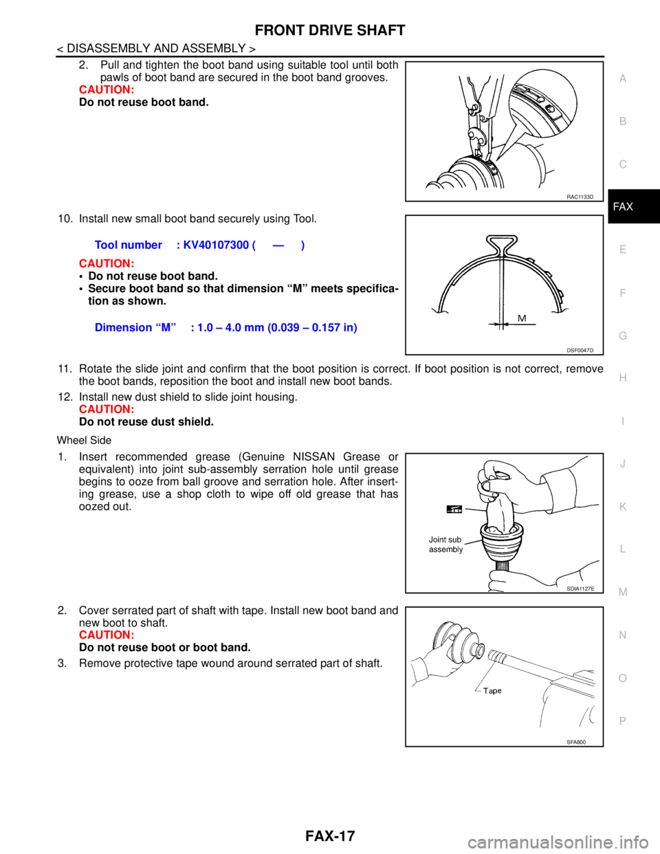
2. Pull and tighten the boot band using suitable tool until both
pawls of boot band are secured in the boot band grooves.
CAUTION:
Do not reuse boot band.
10. Install new small boot band securely using Tool.
CAUTION:
Do not reuse boot band.
Secure boot band so that dimension “M” meets specifica-
tion as shown.
11. Rotate the slide joint and confirm that the boot position is correct. If boot position is not correct, remove
the boot bands, reposition the boot and install new boot bands.
12. Install new dust shield to slide joint housing.
CAUTION:
Do not reuse dust shield.
Wheel Side
1. Insert recommended grease (Genuine NISSAN Grease or
equivalent) into joint sub-assembly serration hole until grease
begins to ooze from ball groove and serration hole. After insert-
ing grease, use a shop cloth to wipe off old grease that has
oozed out.
2. Cover serrated part of shaft with tape. Install new boot band and
new boot to shaft.
CAUTION:
Do not reuse boot or boot band.
3. Remove protective tape wound around serrated part of shaft.
RAC1133D
Tool number : KV40107300 ( — )
Dimension “M” : 1.0 – 4.0 mm (0.039 – 0.157 in)
DSF0047D
SDIA1127E
SFA800