2007 NISSAN TIIDA boot
[x] Cancel search: bootPage 3187 of 5883
FRONT SUSPENSION ASSEMBLY
FSU-11
< REMOVAL AND INSTALLATION >
C
D
F
G
H
I
J
K
L
MA
B
FSU
N
O
P
REMOVAL AND INSTALLATION
FRONT SUSPENSION ASSEMBLY
Removal and InstallationINFOID:0000000001716901
REMOVAL
1. Separate intermediate shaft from steering gear pinion shaft. Refer to ST-9, "Removal and Installation".
2. Remove front tires from vehicle using a power tool.
3. Remove wheel sensor from steering knuckle. Refer to BRC-182, "
Removal and Installation".
CAUTION:
Do not pull on wheel sensor harness.
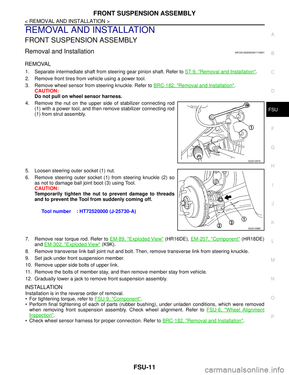
4. Remove the nut on the upper side of stabilizer connecting rod
(1) with a power tool, and then remove stabilizer connecting rod
(1) from strut assembly.
5. Loosen steering outer socket (1) nut.
6. Remove steering outer socket (1) from steering knuckle (2) so
as not to damage ball joint boot (3) using Tool.
CAUTION:
Temporarily tighten the nut to prevent damage to threads
and to prevent the Tool from suddenly coming off.
7. Remove rear torque rod. Refer to EM-89, "
Exploded View" (HR16DE), EM-207, "Component" (HR18DE)
and EM-302, "
Exploded View" (K9K).
8. Remove transverse link ball joint nut and bolt. Then, remove transverse link from steering knuckle.
9. Set jack under front suspension member.
10. Remove upper side bolts of upper link.
11. Remove the bolts of member stay, and then remove member stay from vehicle.
12. Gradually lower a jack to remove front suspension assembly.
INSTALLATION
Installation is in the reverse order of removal.
For tightening torque, refer to FSU-9, "
Component".
Perform final tightening of each of parts (rubber bushing), under unladen conditions, which were removed
when removing front suspension assembly. Check wheel alignment. Refer to FSU-6, "
Wheel Alignment
Inspection".
Check wheel sensor harness for proper connection. Refer to BRC-182, "
Removal and Installation".
SGIA1297E
Tool number : HT72520000 (J-25730-A)
SGIA1298E
Page 3189 of 5883
TRANSVERSE LINK
FSU-13
< REMOVAL AND INSTALLATION >
C
D
F
G
H
I
J
K
L
MA
B
FSU
N
O
P
TRANSVERSE LINK
Removal and InstallationINFOID:0000000001716885
REMOVAL
1. Remove front tires using power tool.
2. Remove transverse link ball joint nut and bolt. Then, remove transverse link from steering knuckle.
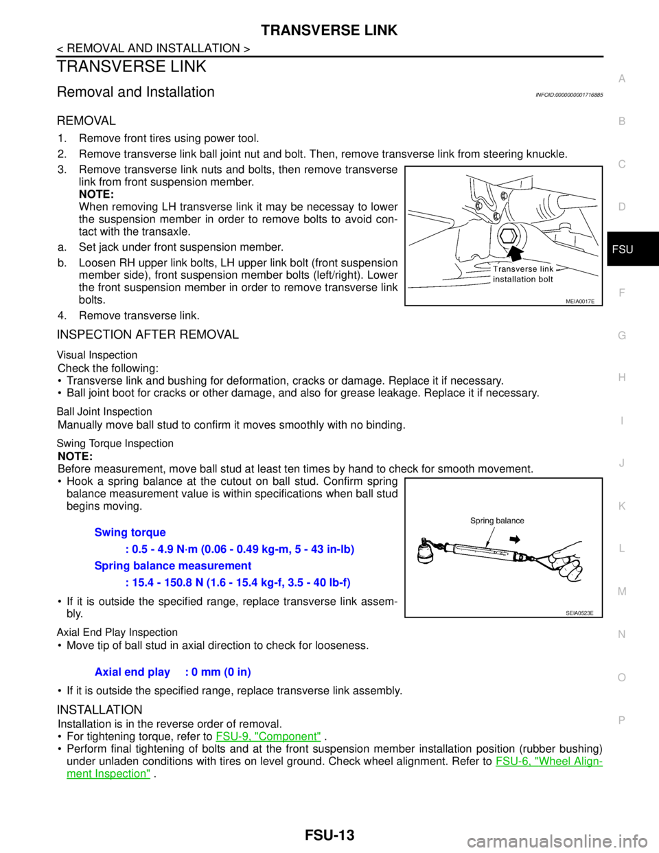
3. Remove transverse link nuts and bolts, then remove transverse
link from front suspension member.
NOTE:
When removing LH transverse link it may be necessay to lower
the suspension member in order to remove bolts to avoid con-
tact with the transaxle.
a. Set jack under front suspension member.
b. Loosen RH upper link bolts, LH upper link bolt (front suspension
member side), front suspension member bolts (left/right). Lower
the front suspension member in order to remove transverse link
bolts.
4. Remove transverse link.
INSPECTION AFTER REMOVAL
Visual Inspection
Check the following:
Transverse link and bushing for deformation, cracks or damage. Replace it if necessary.
Ball joint boot for cracks or other damage, and also for grease leakage. Replace it if necessary.
Ball Joint Inspection
Manually move ball stud to confirm it moves smoothly with no binding.
Swing Torque Inspection
NOTE:
Before measurement, move ball stud at least ten times by hand to check for smooth movement.
Hook a spring balance at the cutout on ball stud. Confirm spring
balance measurement value is within specifications when ball stud
begins moving.
If it is outside the specified range, replace transverse link assem-
bly.
Axial End Play Inspection
Move tip of ball stud in axial direction to check for looseness.
If it is outside the specified range, replace transverse link assembly.
INSTALLATION
Installation is in the reverse order of removal.
For tightening torque, refer to FSU-9, "
Component" .
Perform final tightening of bolts and at the front suspension member installation position (rubber bushing)
under unladen conditions with tires on level ground. Check wheel alignment. Refer to FSU-6, "
Wheel Align-
ment Inspection" .
MEIA0017E
Swing torque
: 0.5 - 4.9 N·m (0.06 - 0.49 kg-m, 5 - 43 in-lb)
Spring balance measurement
: 15.4 - 150.8 N (1.6 - 15.4 kg-f, 3.5 - 40 lb-f)
SEIA0523E
Axial end play : 0 mm (0 in)
Page 3190 of 5883
FSU-14
< REMOVAL AND INSTALLATION >
STABILIZER BAR
STABILIZER BAR
Removal and InstallationINFOID:0000000001716884
REMOVAL
1. Separate intermediate shaft from steering gear pinion shaft. Refer to ST-9, "Removal and Installation" .
2. Remove front tires using power tool.
3. Remove the nut on the lower side of stabilizer connecting rod using power tool, and then remove stabilizer
connecting rod from stabilizer bar.
4. If necessary remove stabilize connecting rod upper nut using power tool. Separate stabilizer connecting
rod and strut.
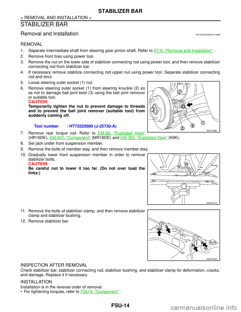
5. Loose steering outer socket (1) nut.
6. Remove steering outer socket (1) from steering knuckle (2) so
as not to damage ball joint boot (3) using the ball joint remover
or suitable tool.
CAUTION:
Temporarily tighten the nut to prevent damage to threads
and to prevent the ball joint remover (suitable tool) from
suddenly coming off.
7. Remove rear torque rod. Refer to EM-89, "
Exploded View"
(HR16DE), EM-207, "Component" (MR18DE) and EM-302, "Exploded View" (K9K).
8. Set jack under front suspension member.
9. Remove the bolts of member stay, and then remove member stay.
10. Gradually lower front suspension member in order to remove
stabilizer bolts.
CAUTION:
Be careful not to lower it too far. (Do not over load the
links.)
11. Remove the bolts of stabilizer clamp, and then remove stabilizer
clamp and stabilizer bushing.
12. Remove stabilizer bar.
INSPECTION AFTER REMOVAL
Check stabilizer bar, stabilizer connecting rod, stabilizer bushing, and stabilizer clamp for deformation, cracks,
and damage. Replace it if necessary.
INSTALLATION
Installation is in the reverse order of removal.
For tightening torques, refer to FSU-9, "
Component" . Tool number : HT72520000 (J-25730-A)
SGIA1298E
WEIA0181E
WEIA0182E
Page 3199 of 5883
HOW TO USE THIS MANUAL
GI-5
< HOW TO USE THIS MANUAL >
C
D
E
F
G
H
I
J
K
L
MB
GI
N
O
P
SYMBOLS
How to Follow Trouble DiagnosisINFOID:0000000001606148
DESCRIPTION
NOTICE:
Trouble diagnoses indicate work procedures required to diagnose problems effectively. Observe the following
instructions before diagnosing.
1.Before performing trouble diagnoses, read the “Preliminary Check”, the “Symptom Chart” or the
“Work Flow”.
2.After repairs, re-check that the problem has been completely eliminated.
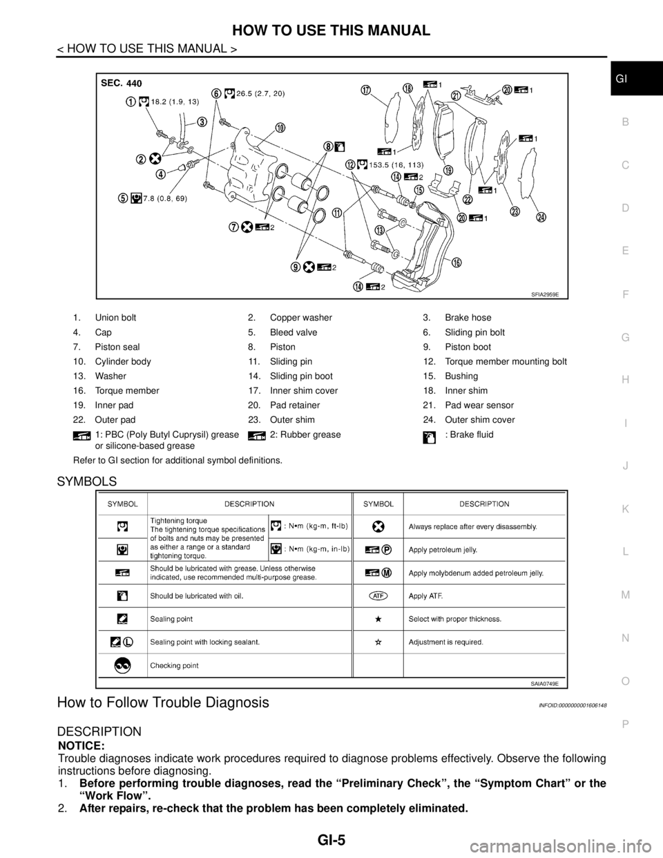
1. Union bolt 2. Copper washer 3. Brake hose
4. Cap 5. Bleed valve 6. Sliding pin bolt
7. Piston seal 8. Piston 9. Piston boot
10. Cylinder body 11. Sliding pin 12. Torque member mounting bolt
13. Washer 14. Sliding pin boot 15. Bushing
16. Torque member 17. Inner shim cover 18. Inner shim
19. Inner pad 20. Pad retainer 21. Pad wear sensor
22. Outer pad 23. Outer shim 24. Outer shim cover
1: PBC (Poly Butyl Cuprysil) grease
or silicone-based grease2: Rubber grease : Brake fluid
Refer to GI section for additional symbol definitions.
SFIA2959E
SAIA0749E
Page 3726 of 5883
INSTRUMENT PANEL ASSEMBLY
IP-11
< SERVICE INFORMATION >
C
D
E
F
G
H
I
K
L
MA
B
IP
N
O
P
NOTE:
The LHD model shown, RHD similar.
Removal and InstallationINFOID:0000000001523318
NOTE:
The LHD model shown, RHD model similar.
WORK STEPS
When removing instrument panel & pad, cluster lid A, cluster lid C, passenger air bag module assembly and
center console assembly, follow steps in the order shown.
CAUTION:
Disconnect both battery cables.
Never tamper with or force air bag lid open, as this may adversely affect air bag performance.
Be careful not to scratch pad and other parts.
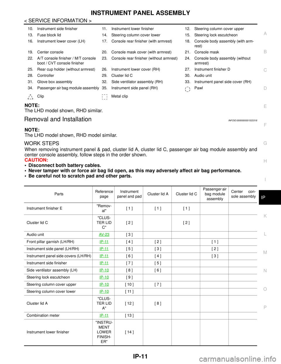
10. Instrument side finisher 11. Instrument lower finisher 12. Steering column cover upper
13. Fuse block lid 14. Steering column cover lower 15. Steering lock escutcheon
16. Instrument lower cover (LH) 17. Console rear finisher (with armrest) 18. Console body assembly (with arm-
rest)
19. Center console 20. Console mask cover (with armrest) 21. Console mask
22. A/T console finisher / M/T console
boot / CVT console finisher23. Console rear finisher (without armrest) 24. Console body assembly (without
armrest)
25. Rear cup holder (without armrest) 26. Instrument lower cover (RH) 27. Instrument finisher D
28. Controller 29. Cluster lid C 30. Audio unit
31. Glove box assembly 32. Side ventilator assembly (RH) 33. Instrument panel side cover (RH)
34. Passenger air bag module assembly 35. Instrument side panel (RH) Pawl
Clip Metal clip
PartsReference
pageInstrument
panel and padCluster lid A Cluster lid C Passenger air
bag module
assemblyCenter con-
sole assembly
Instrument finisher E"Remov-
al"[ 1 ] [ 1 ] [ 1 ]
Cluster lid C"CLUS-
TER LID
C"[ 2 ] [ 2 ]
Audio unitAV- 2 3
[ 3 ]
Front pillar garnish (LH/RH)IP-11
[ 4 ] [ 2 ] [ 1 ]
Instrument side panel (LH/RH)IP-11
[ 5 ] [ 3 ] [ 2 ]
Instrument panel side covers (LH/RH)IP-11
[ 6 ] [ 4 ] [ 3 ]
Instrument side finisherIP-11
[ 7 ] [ 5 ]
Side ventilator assembly (LH)IP-10
[ 8 ] [ 6 ]
Steering lock escutcheonIP-10
[ 9 ]
Steering column cover upperIP-10
[ 10 ] [ 7 ]
Steering column cover lowerIP-10
[ 11 ]
Cluster lid A"CLUS-
TER LID
A"[ 12 ] [ 8 ]
Combination meterIP-11
[ 13 ]
Instrument lower finisher"INSTRU-
MENT
LOWER
FINISH-
ER"[ 14 ]
Page 3727 of 5883
![NISSAN TIIDA 2007 Service Repair Manual IP-12
< SERVICE INFORMATION >
INSTRUMENT PANEL ASSEMBLY
[ ]: Number indicates step in removal procedures.
INSTRUMENT PANEL ASSEMBLY
Removal
1. Pull instrument finisher E backward by approximately 30
d](/manual-img/5/57395/w960_57395-3726.png "NISSAN TIIDA 2007 Service Repair Manual IP-12
< SERVICE INFORMATION >
INSTRUMENT PANEL ASSEMBLY
[ ]: Number indicates step in removal procedures.
INSTRUMENT PANEL ASSEMBLY
Removal
1. Pull instrument finisher E backward by approximately 30
d")
IP-12
< SERVICE INFORMATION >
INSTRUMENT PANEL ASSEMBLY
[ ]: Number indicates step in removal procedures.
INSTRUMENT PANEL ASSEMBLY
Removal
1. Pull instrument finisher E backward by approximately 30
degrees while disengaging the instrument finisher E metal clips
and pawl.
Glove box assembly"GLOVE
BOX AS-
SEMBLY"[ 15 ]
Side ventilator assembly (RH)IP-10
[ 16 ] [ 4 ]
Passenger air bag module assemblySR-9
[ 17 ] [ 5 ]
Instrument upper maskIP-10
[ 18 ]
Instrument finisher DIP-10
[ 19 ]
Controller TM-674
[ 20 ]
Instrument upper panel assembly IP-11
[ 21 ]
Console mask"Remov-
al"[ 22 ] [ 1 ]
CVT, A/T console finisherIP-23
[ 23 ] [ 2 ]
M/T console bootIP-23
[ 23 ] [ 2 ]
Console rear finisherIP-23
[ 24 ] [ 3 ]
Console mask cover (with arm rest)IP-23
[ 25 ] [ 4 ]
Rear cup holder (without arm rest)IP-23
[ 25 ] [ 4 ]
Console body assemblyIP-23
[ 26 ] [ 5 ]
Instrument lower cover (LH/RH)"INSTRU-
MENT
LOWER
FINISH-
ER"[ 27 ] [ 6 ]
Center console assembly"CEN-
TER
CON-
SOLE AS-
SEMBLY"[ 28 ] [ 7 ]
Fuse block lidIP-10
[ 29 ]
Lighting and turn signal switchEXL-101
[ 30 ]
Wiper & washer switchWW-76
[ 31 ]
Instrument panel & padIP-10
[ 32 ] PartsReference
pageInstrument
panel and padCluster lid A Cluster lid C Passenger air
bag module
assemblyCenter con-
sole assembly
WIIA1224E
Page 3737 of 5883
IP-22
< SERVICE INFORMATION >
INSTRUMENT PANEL ASSEMBLY
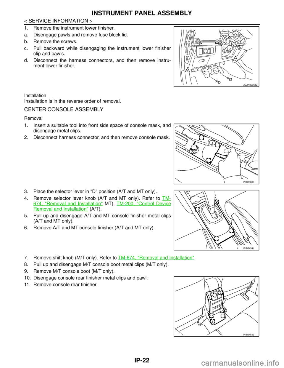
1. Remove the instrument lower finisher.
a. Disengage pawls and remove fuse block lid.
b. Remove the screws.
c. Pull backward while disengaging the instrument lower finisher
clip and pawls.
d. Disconnect the harness connectors, and then remove instru-
ment lower finisher.
Installation
Installation is in the reverse order of removal.
CENTER CONSOLE ASSEMBLY
Removal
1. Insert a suitable tool into front side space of console mask, and
disengage metal clips.
2. Disconnect harness connector, and then remove console mask.
3. Place the selector lever in "D" position (A/T and MT only).
4. Remove selector lever knob (A/T and MT only). Refer to TM-
674, "Removal and Installation" MT), TM-200, "Control Device
Removal and Installation" (A/T).
5. Pull up and disengage A/T and MT console finisher metal clips
(A/T and MT only).
6. Remove A/T and MT console finisher (A/T and MT only).
7. Remove shift knob (M/T only). Refer to TM-674, "
Removal and Installation".
8. Pull up and disengage M/T console boot metal clips (M/T only).
9. Remove M/T console boot (M/T only).
10. Disengage console rear finisher metal clips and pawl.
11. Remove console rear finisher.
ALJIA0096ZZ
PIIB6386E
PIIB2454J
PIIB2452J
Page 4296 of 5883
MA-56
< ON-VEHICLE MAINTENANCE >
CHASSIS AND BODY MAINTENANCE
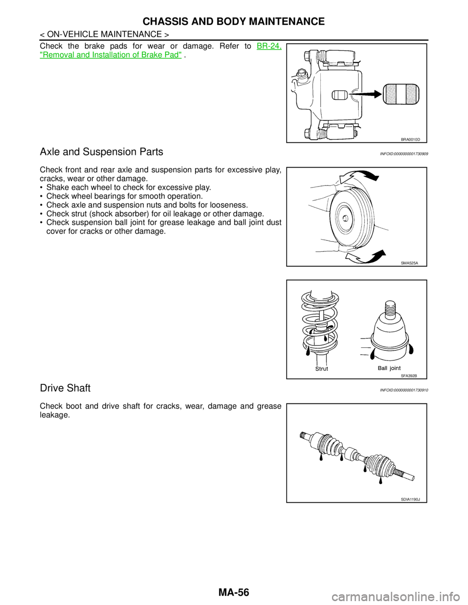
Check the brake pads for wear or damage. Refer to BR-24,
"Removal and Installation of Brake Pad" .
Axle and Suspension PartsINFOID:0000000001730909
Check front and rear axle and suspension parts for excessive play,
cracks, wear or other damage.
Shake each wheel to check for excessive play.
Check wheel bearings for smooth operation.
Check axle and suspension nuts and bolts for looseness.
Check strut (shock absorber) for oil leakage or other damage.
Check suspension ball joint for grease leakage and ball joint dust
cover for cracks or other damage.
Drive ShaftINFOID:0000000001730910
Check boot and drive shaft for cracks, wear, damage and grease
leakage.
BRA0010D
SMA525A
SFA392B
SDIA1190J