2007 NISSAN TIIDA oil level
[x] Cancel search: oil levelPage 4345 of 5883

MWI-38
< ECU DIAGNOSIS >
COMBINATION METER
36 L Oil level sensor signal ON —Refer to MWI-32, "
Component Inspec-
tion (With Diesel)" or MWI-33, "Compo-
nent Inspection (Without Diesel)".
NOTE:
The measurement cannot be performed
because the signal is only input for a
moment when the ignition switch is
turned ON.
37 O Oil level sensor signal ground ON — 0
38 L Generator ONGenerator voltage low 0
Generator voltage normal Battery voltage Te r -
mi-
nal
No.Wire
colorItemCondition
Reference value (V)
(Approx.) Ignition
switchOperation or condition
Page 4575 of 5883

PRECAUTIONS
RSU-3
< PRECAUTION >
C
D
F
G
H
I
J
K
L
MA
B
RSU
N
O
P
PRECAUTION
PRECAUTIONS
Precaution for Supplemental Restraint System (SRS) "AIR BAG" and "SEAT BELT
PRE-TENSIONER"
INFOID:0000000001724583
The Supplemental Restraint System such as “AIR BAG” and “SEAT BELT PRE-TENSIONER”, used along
with a front seat belt, helps to reduce the risk or severity of injury to the driver and front passenger for certain
types of collision. This system includes seat belt switch inputs and dual stage front air bag modules. The SRS
system uses the seat belt switches to determine the front air bag deployment, and may only deploy one front
air bag, depending on the severity of a collision and whether the front occupants are belted or unbelted.
Information necessary to service the system safely is included in the SRS and SB section of this Service Man-
ual.
WARNING:
• To avoid rendering the SRS inoperative, which could increase the risk of personal injury or death in
the event of a collision which would result in air bag inflation, all maintenance must be performed by
an authorized NISSAN/INFINITI dealer.
Improper maintenance, including incorrect removal and installation of the SRS, can lead to personal
injury caused by unintentional activation of the system. For removal of Spiral Cable and Air Bag
Module, see the SRS section.
Do not use electrical test equipment on any circuit related to the SRS unless instructed to in this
Service Manual. SRS wiring harnesses can be identified by yellow and/or orange harnesses or har-
ness connectors.
Precaution for Rear SuspensionINFOID:0000000001724584
When installing the rubber bushings, the final tightening must be done under unladen condition and with the
tires on level ground. Oil will shorten the life of the rubber bushings, so wipe off any spilled oil immediately.
Unladen condition means the fuel tank, engine coolant and lubricants are at the full specification. The spare
tire, jack, hand tools, and mats are in their designated positions.
After installing suspension components, check the wheel alignment.
Caulking nuts are not reusable. Always use new caulking nuts for installation. New caulking nuts are pre-
oiled, do not apply any additional lubrication.
Page 4577 of 5883

REAR SUSPENSION ASSEMBLY
RSU-5
< ON-VEHICLE MAINTENANCE >
C
D
F
G
H
I
J
K
L
MA
B
RSU
N
O
P
ON-VEHICLE MAINTENANCE
REAR SUSPENSION ASSEMBLY
On-Vehicle Inspection and ServiceINFOID:0000000001724575
Make sure the mounting conditions (looseness, backlash) of each component and component conditions
(wear, damage) are within specifications.
SHOCK ABSORBER INSPECTION
Check shock absorber for oil leakage, damage and replace it if necessary.
Wheel AlignmentINFOID:0000000001724576
DESCRIPTION
Measure wheel alignment under unladen conditions.
NOTE:
“Unladen conditions” means that fuel, engine coolant, and lubricant are full. Spare tire, jack, hand tools and
mats are in designated positions.
PRELIMINARY
Check the following:
1. Tires for improper air pressure and wear.
2. Road wheels for runout. Refer to WT-5, "
Inspection" .
3. Wheel bearing axial end play. Refer to RAX-5, "
On-Vehicle Inspection and Service" .
4. Shock absorber operation.
5. Each mounting part of suspension for looseness and deformation.
6. Rear suspension beam for cracks, deformation, and other damage.
7. Vehicle height (posture).
GENERAL INFORMATION AND RECOMMENDATIONS
1. A Four-Wheel Thrust Alignment should be performed.
This type of alignment is recommended for any NISSAN vehicle.
The four-wheel “thrust” process helps ensure that the vehicle is properly aligned and the steering wheel
is centered.
The alignment machine itself should be capable of accepting any NISSAN vehicle.
The alignment machine should be checked to ensure that it is level.
2. Make sure the alignment machine is properly calibrated.
Your alignment machine should be regularly calibrated in order to give correct information.
Check with the manufacturer of your specific alignment machine for their recommended Service/Cali-
bration Schedule.
THE ALIGNMENT PROCESS
IMPORTANT: Use only the alignment specifications listed in this Service Manual. Refer to RSU-5, "Wheel
Alignment" .
1. When displaying the alignment settings, many alignment machines use “indicators”: (Green/red, plus or
minus, Go/No Go). Do NOT use these indicators.
The alignment specifications programmed into your alignment machine that operate these indicators
may not be correct.
This may result in an ERROR.
2. Some newer alignment machines are equipped with an optional “Rolling Compensation” method to “com-
pensate” the sensors (alignment targets or head units). Do NOT use this “Rolling Compensation”
method.
Use the “Jacking Compensation” method. After installing the alignment targets or head units, raise the
vehicle and rotate the wheels 1/2 turn both ways.
See Instructions in the alignment machine you are using for more information.
CAMBER INSPECTION
Page 4583 of 5883

REAR SUSPENSION BEAM
RSU-11
< ON-VEHICLE REPAIR >
C
D
F
G
H
I
J
K
L
MA
B
RSU
N
O
P
REAR SUSPENSION BEAM
Removal and InstallationINFOID:0000000001724580
REMOVAL
1. Remove rear tires from vehicle using power tool.
2. Separate parking brake rear cable from rear drum brake and rear suspension beam. Refer to PB-4, "
On-
Vehicle Service" .
3. Remove wheel sensor and wheel sensor harness from wheel hub and bearing assembly and rear suspen-
sion beam. Refer to BRC-83, "
Removal and Installation" .
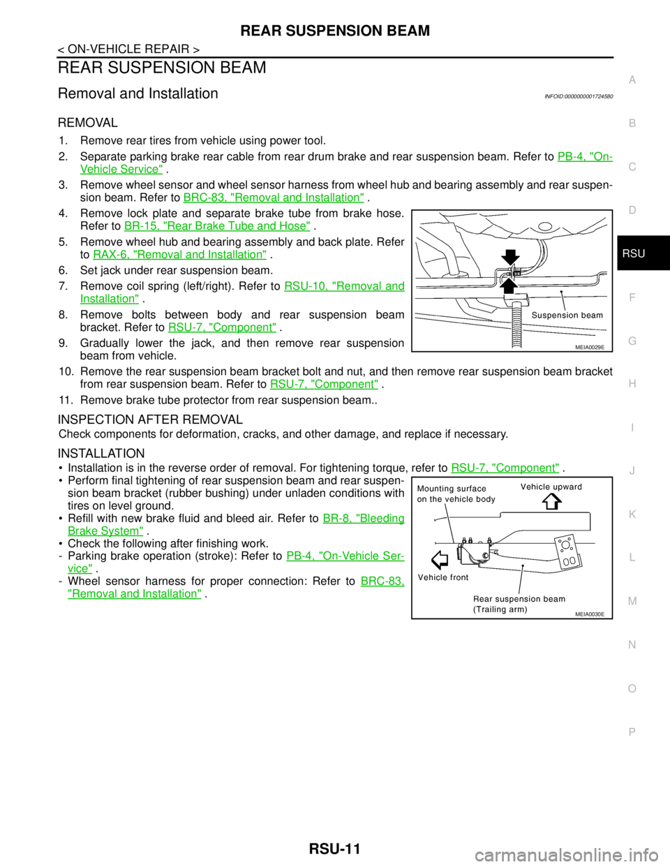
4. Remove lock plate and separate brake tube from brake hose.
Refer to BR-15, "
Rear Brake Tube and Hose" .
5. Remove wheel hub and bearing assembly and back plate. Refer
to RAX-6, "
Removal and Installation" .
6. Set jack under rear suspension beam.
7. Remove coil spring (left/right). Refer to RSU-10, "
Removal and
Installation" .
8. Remove bolts between body and rear suspension beam
bracket. Refer to RSU-7, "
Component" .
9. Gradually lower the jack, and then remove rear suspension
beam from vehicle.
10. Remove the rear suspension beam bracket bolt and nut, and then remove rear suspension beam bracket
from rear suspension beam. Refer to RSU-7, "
Component" .
11. Remove brake tube protector from rear suspension beam..
INSPECTION AFTER REMOVAL
Check components for deformation, cracks, and other damage, and replace if necessary.
INSTALLATION
Installation is in the reverse order of removal. For tightening torque, refer to RSU-7, "Component" .
Perform final tightening of rear suspension beam and rear suspen-
sion beam bracket (rubber bushing) under unladen conditions with
tires on level ground.
Refill with new brake fluid and bleed air. Refer to BR-8, "
Bleeding
Brake System" .
Check the following after finishing work.
- Parking brake operation (stroke): Refer to PB-4, "
On-Vehicle Ser-
vice" .
- Wheel sensor harness for proper connection: Refer to BRC-83,
"Removal and Installation" .
MEIA0029E
MEIA0030E
Page 4974 of 5883
![NISSAN TIIDA 2007 Service Repair Manual TM-28
< FUNCTION DIAGNOSIS >[TYPE 1 (4AT: RE4F03B)]
A/T CONTROL SYSTEM
Control Valve
INFOID:0000000001694429
FUNCTION OF CONTROL VALVES
Centrifugal Cancel MechanismINFOID:0000000001694419
FUNCTION
The NISSAN TIIDA 2007 Service Repair Manual TM-28
< FUNCTION DIAGNOSIS >[TYPE 1 (4AT: RE4F03B)]
A/T CONTROL SYSTEM
Control Valve
INFOID:0000000001694429
FUNCTION OF CONTROL VALVES
Centrifugal Cancel MechanismINFOID:0000000001694419
FUNCTION
The](/manual-img/5/57395/w960_57395-4973.png)
TM-28
< FUNCTION DIAGNOSIS >[TYPE 1 (4AT: RE4F03B)]
A/T CONTROL SYSTEM
Control Valve
INFOID:0000000001694429
FUNCTION OF CONTROL VALVES
Centrifugal Cancel MechanismINFOID:0000000001694419
FUNCTION
The centrifugal cancel mechanism is a mechanism to cancel the centrifugal hydraulic pressure instead of the
conventional check balls. It cancels the centrifugal hydraulic pressure which is generated as high clutch drum
rotates, and it allows for preventing high clutch from dragging and for providing stable high clutch piston press-
ing force in all revolution speeds.
STRUCTURE/OPERATION
Valve name Function
Pressure regulator valve, plug and sleeve
plugRegulates oil discharged from the oil pump to provide optimum line pressure for all driving
conditions.
Pressure modifier valve and sleeve Used as a signal supplementary valve to the pressure regulator valve. Regulates pres-
sure-modifier pressure (signal pressure) which controls optimum line pressure for all driv-
ing conditions.
Pilot valve Regulates line pressure to maintain a constant pilot pressure level which controls lock-up
mechanism, overrun clutch, shift timing.
Accumulator control valve Regulates accumulator back-pressure to pressure suited to driving conditions.
Manual valve Directs line pressure to oil circuits corresponding to select positions.
Hydraulic pressure drains when the shift lever is in Neutral.
Shift valve A Simultaneously switches three oil circuits using output pressure of shift solenoid valve A
to meet driving conditions (vehicle speed, throttle opening, etc.).
Provides automatic downshifting and upshifting (1st → 2nd → 3rd → 4th gears/4th → 3rd
→ 2nd → 1st gears) in combination with shift valve B.
Shift valve B Simultaneously switches two oil circuits using output pressure of shift solenoid valve B in
relation to driving conditions (vehicle speed, throttle opening, etc.).
Provides automatic downshifting and upshifting (1st → 2nd → 3rd → 4th gears/4th → 3rd
→ 2nd → 1st gears) in combination with shift valve A.
Overrun clutch control valve Switches hydraulic circuits to prevent engagement of the overrun clutch simultaneously
with application of the brake band in D
4. (Interlocking occurs if the overrun clutch engages
during D
4.)
1st reducing valve Reduces low & reverse brake pressure to dampen engine-brake shock when downshift-
ing from the 1st position 1
2 to 11.
Overrun clutch reducing valve Reduces oil pressure directed to the overrun clutch and prevents engine-brake shock.
In the 1st and 2nd positions, line pressure acts on the overrun clutch reducing valve to
increase the pressure-regulating point, with resultant engine brake capability.
Torque converter relief valve Prevents an excessive rise in torque converter pressure.
Torque converter clutch control valve, plug
and sleeveActivates or inactivates the lock-up function.
Also provides smooth lock-up through transient application and release of the lock-up
system.
1-2 accumulator valve and piston Lessens the shock find when the 2nd gear band servo contracts, and provides smooth
shifting.
3-2 timing valve Switches the pace that oil pressure is released depending on vehicle speed; maximizes
the high clutch release timing, and allows for soft downshifting.
Shuttle valve Determines if the overrun clutch solenoid valve should control the 3-2 timing valve or the
overrun clutch control valve and switches between the two.
Cooler check valve At low speeds and with a small load when a little heat is generated, saves the volume of
cooler flow, and stores the oil pressure for lock-up.
Page 5079 of 5883
![NISSAN TIIDA 2007 Service Repair Manual SYSTEM SYMPTOM
TM-133
< SYMPTOM DIAGNOSIS >[TYPE 1 (4AT: RE4F03B)]
C
E
F
G
H
I
J
K
L
MA
B
TM
N
O
P
Slips/Will Not EngageVehicle will not run in
“D”, “1”, “2” positions
(but runs in R pos NISSAN TIIDA 2007 Service Repair Manual SYSTEM SYMPTOM
TM-133
< SYMPTOM DIAGNOSIS >[TYPE 1 (4AT: RE4F03B)]
C
E
F
G
H
I
J
K
L
MA
B
TM
N
O
P
Slips/Will Not EngageVehicle will not run in
“D”, “1”, “2” positions
(but runs in R pos](/manual-img/5/57395/w960_57395-5078.png)
SYSTEM SYMPTOM
TM-133
< SYMPTOM DIAGNOSIS >[TYPE 1 (4AT: RE4F03B)]
C
E
F
G
H
I
J
K
L
MA
B
TM
N
O
P
Slips/Will Not EngageVehicle will not run in
“D”, “1”, “2” positions
(but runs in R posi-
tion). Clutch slips.
Very poor accelera-
tion.ON vehicle1. A/T fluid levelTM-171
2. Stall testTM-175
3. Line pressure testTM-178
4. Line pressure solenoid valveTM-81
5. Control valve assemblyTM-191
6. Accumulator N-DTM-191
OFF vehicle7. Reverse clutchTM-258
8. High clutchTM-262
9. Forward clutchTM-267
10. Forward one-way clutchTM-278
11. Low one-way clutchTM-222
Clutches or brakes
slip somewhat in start-
ing.ON vehicle1. A/T fluid levelTM-171
2. Control cable adjustmentTM-204
3. Accelerator pedal position sensorEC-297
4. Line pressure testTM-178
5. Line pressure solenoid valveTM-81
6. Control valve assemblyTM-191
7. Accumulator N-DTM-191
OFF vehicle8. Forward clutchTM-267
9. Reverse clutchTM-258
10. Low & reverse brakeTM-273
11. Oil pumpTM-240
12. Torque converterTM-222
No creep at all.
TM-142
, TM-144
ON vehicle1. A/T fluid levelTM-1712. Line pressure testTM-178
3. Control valve assemblyTM-191
OFF vehicle4. Forward clutchTM-2675. Oil pumpTM-240
6. Torque converterTM-222
Almost no shock or
clutches slipping in
change from D
1 to D2.ON vehicle1. A/T fluid levelTM-171
2. Accelerator pedal position sensorEC-297
3. Line pressure testTM-178
4. Accumulator servo releaseTM-191
5. Control valve assemblyTM-191
OFF vehicle 6. Brake bandTM-287
Items Symptom Condition Diagnostic item Reference page
Page 5081 of 5883
![NISSAN TIIDA 2007 Service Repair Manual SYSTEM SYMPTOM
TM-135
< SYMPTOM DIAGNOSIS >[TYPE 1 (4AT: RE4F03B)]
C
E
F
G
H
I
J
K
L
MA
B
TM
N
O
P
Slips/Will Not EngageRaces extremely fast
or slips in changing
from D
3 to D2 when
depressing acce NISSAN TIIDA 2007 Service Repair Manual SYSTEM SYMPTOM
TM-135
< SYMPTOM DIAGNOSIS >[TYPE 1 (4AT: RE4F03B)]
C
E
F
G
H
I
J
K
L
MA
B
TM
N
O
P
Slips/Will Not EngageRaces extremely fast
or slips in changing
from D
3 to D2 when
depressing acce](/manual-img/5/57395/w960_57395-5080.png)
SYSTEM SYMPTOM
TM-135
< SYMPTOM DIAGNOSIS >[TYPE 1 (4AT: RE4F03B)]
C
E
F
G
H
I
J
K
L
MA
B
TM
N
O
P
Slips/Will Not EngageRaces extremely fast
or slips in changing
from D
3 to D2 when
depressing accelera-
tor pedal. ON vehicle1. A/T fluid levelTM-171
2. Accelerator pedal position sensor EC-297
3. Line pressure testTM-178
4. Line pressure solenoid valveTM-81
5. Shift solenoid valve BTM-89
6. Control valve assemblyTM-191
OFF vehicle7. Brake bandTM-2878. High clutchTM-262
Races extremely fast
or slips in changing
from D
4 or D3 to D 1
when depressing ac-
celerator pedal.ON vehicle1. A/T fluid levelTM-171
2. Accelerator pedal position sensorEC-297
3. Line pressure testTM-178
4. Line pressure solenoid valveTM-81
5. Shift solenoid valve ATM-85
6. Shift solenoid valve BTM-89
7. Control valve assemblyTM-191
OFF vehicle8. Forward clutchTM-2679. Forward one-way clutchTM-278
10. Low one-way clutchTM-222
Vehicle will not run in
any position.ON vehicle1. A/T fluid levelTM-171
2. Control cable adjustmentTM-204
3. Line pressure testTM-178
4. Line pressure solenoid valveTM-81
OFF vehicle5. Oil pumpTM-240
6. High clutchTM-262
7. Brake bandTM-287
8. Low & reverse brakeTM-273
9. Torque converterTM-222
10. Parking componentsTM-213
OthersEngine cannot be
started in “P” and “N”
positions.
TM-140
ON vehicle1. Ignition switch and starterSTR-62. Control cable adjustmentTM-204
3. PNP switch adjustmentTM-195
Engine starts in posi-
tions other than “P”
and “N”.ON vehicle1. Control cable adjustmentTM-204
2. PNP switch adjustmentTM-195
Items Symptom Condition Diagnostic item Reference page
Page 5082 of 5883
![NISSAN TIIDA 2007 Service Repair Manual TM-136
< SYMPTOM DIAGNOSIS >[TYPE 1 (4AT: RE4F03B)]
SYSTEM SYMPTOM
OthersTransaxle noise in“ P”
and “N” positions.ON vehicle1. A/T fluid levelTM-171
2. Line pressure testTM-178
3. Accelerator NISSAN TIIDA 2007 Service Repair Manual TM-136
< SYMPTOM DIAGNOSIS >[TYPE 1 (4AT: RE4F03B)]
SYSTEM SYMPTOM
OthersTransaxle noise in“ P”
and “N” positions.ON vehicle1. A/T fluid levelTM-171
2. Line pressure testTM-178
3. Accelerator](/manual-img/5/57395/w960_57395-5081.png)
TM-136
< SYMPTOM DIAGNOSIS >[TYPE 1 (4AT: RE4F03B)]
SYSTEM SYMPTOM
OthersTransaxle noise in“ P”
and “N” positions.ON vehicle1. A/T fluid levelTM-171
2. Line pressure testTM-178
3. Accelerator pedal position sensorEC-297
4. Vehicle speed sensor·A/T (Revolution sensor)
and vehicle speed sensor·MTRTM-52 and TM-97
OFF vehicle5. Oil pumpTM-2406. Torque converterTM-222
Vehicle moves when
changing into “P” po-
sition or parking gear
does not disengage
when shifted out of “P”
position.ON vehicle 1. Control cable adjustmentTM-204
OFF vehicle 2. Parking componentsTM-213
Vehicle runs in “N” po-
sition.
TM-141
ON vehicle 1. Control cable adjustmentTM-204
OFF vehicle2. Forward clutchTM-2673. Reverse clutchTM-258
4. Overrun clutchTM-267
Vehicle braked when
shifting into “R” posi-
tion.ON vehicle1. A/T fluid levelTM-171
2. Control cable adjustmentTM-204
3. Line pressure testTM-178
4. Line pressure solenoid valveTM-81
5. Control valve assemblyTM-191
OFF vehicle6. High clutchTM-2627. Brake band TM-287
8. Forward clutchTM-267
9. Overrun clutchTM-267
Excessive creep. ON vehicle 1. Engine idling speedEC-26
Engine stops when
shifting lever into “R”,
“D”, “2” and “1” posi-
tions.ON vehicle1. Engine idling speedEC-262. A/T fluid levelTM-171
3. Torque converter clutch solenoid valveTM-73
4. Control valve assemblyTM-191
OFF vehicle 5. Torque converterTM-222
Vehicle braked by
gear change from D
1
to D
2.ON vehicle 1. A/T fluid levelTM-171OFF vehicle2. Reverse clutchTM-2583. Low & reverse brakeTM-273
4. High clutchTM-262
5. Low one-way clutchTM-222
Vehicle braked by
gear change from D
2
to D
3.ON vehicle 1. A/T fluid levelTM-171OFF vehicle 2. Brake bandTM-287
Items Symptom Condition Diagnostic item Reference page