2007 NISSAN TIIDA radiator
[x] Cancel search: radiatorPage 3123 of 5883

FRONT GRILLE
EXT-19
< ON-VEHICLE REPAIR >
C
D
E
F
G
H
I
J
L
MA
B
EXT
N
O
P
FRONT GRILLE
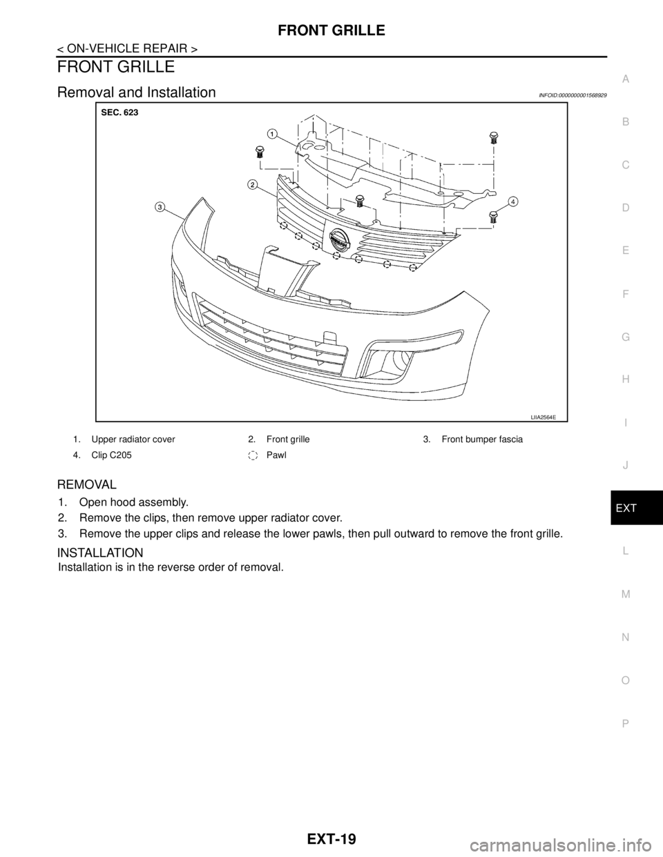
Removal and InstallationINFOID:0000000001568929
REMOVAL
1. Open hood assembly.
2. Remove the clips, then remove upper radiator cover.
3. Remove the upper clips and release the lower pawls, then pull outward to remove the front grille.
INSTALLATION
Installation is in the reverse order of removal.
LIIA2564E
1. Upper radiator cover 2. Front grille 3. Front bumper fascia
4. Clip C205 Pawl
Page 3238 of 5883

GI-44
< PRECAUTION >
PRECAUTIONS
General Precaution
INFOID:0000000001606118
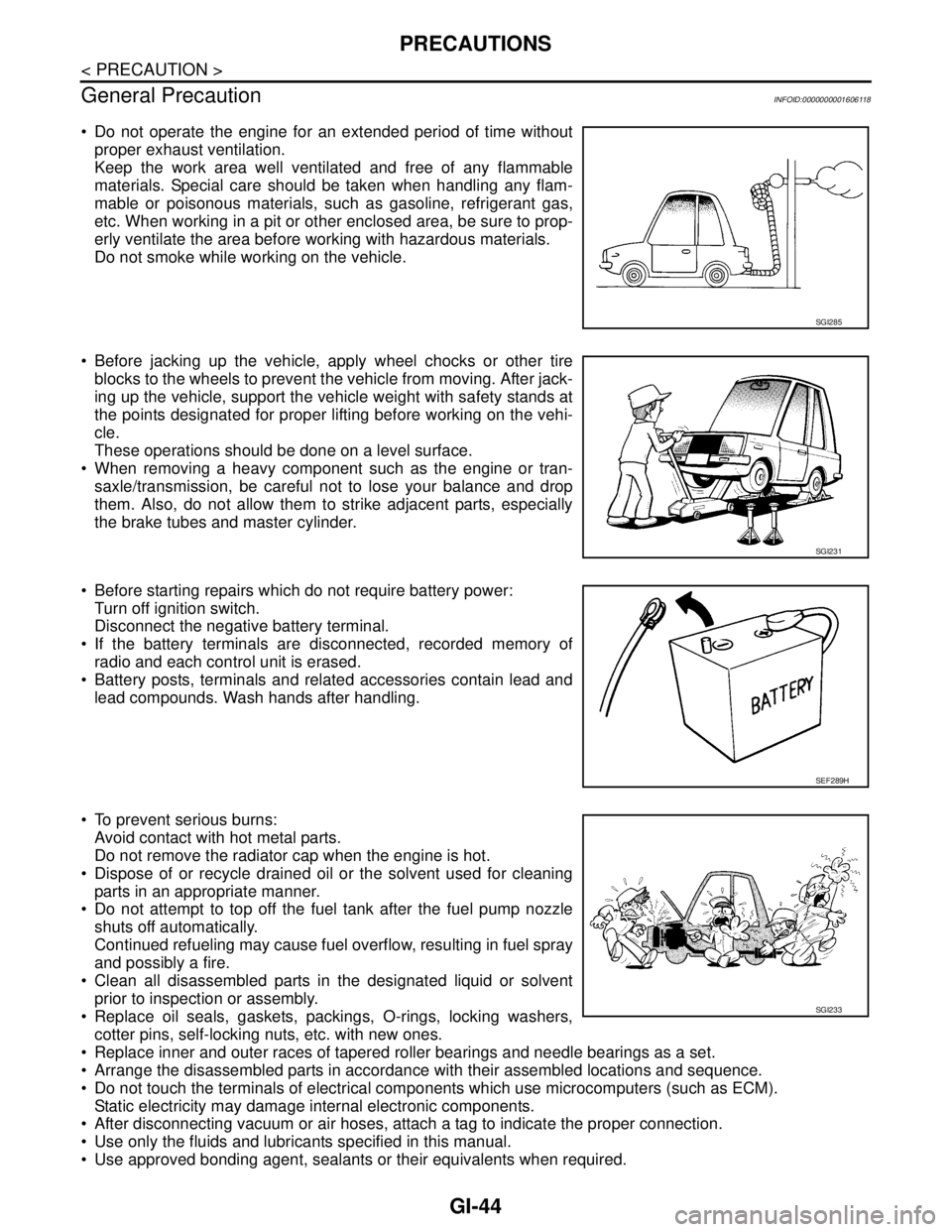
Do not operate the engine for an extended period of time without
proper exhaust ventilation.
Keep the work area well ventilated and free of any flammable
materials. Special care should be taken when handling any flam-
mable or poisonous materials, such as gasoline, refrigerant gas,
etc. When working in a pit or other enclosed area, be sure to prop-
erly ventilate the area before working with hazardous materials.
Do not smoke while working on the vehicle.
Before jacking up the vehicle, apply wheel chocks or other tire
blocks to the wheels to prevent the vehicle from moving. After jack-
ing up the vehicle, support the vehicle weight with safety stands at
the points designated for proper lifting before working on the vehi-
cle.
These operations should be done on a level surface.
When removing a heavy component such as the engine or tran-
saxle/transmission, be careful not to lose your balance and drop
them. Also, do not allow them to strike adjacent parts, especially
the brake tubes and master cylinder.
Before starting repairs which do not require battery power:
Turn off ignition switch.
Disconnect the negative battery terminal.
If the battery terminals are disconnected, recorded memory of
radio and each control unit is erased.
Battery posts, terminals and related accessories contain lead and
lead compounds. Wash hands after handling.
To prevent serious burns:
Avoid contact with hot metal parts.
Do not remove the radiator cap when the engine is hot.
Dispose of or recycle drained oil or the solvent used for cleaning
parts in an appropriate manner.
Do not attempt to top off the fuel tank after the fuel pump nozzle
shuts off automatically.
Continued refueling may cause fuel overflow, resulting in fuel spray
and possibly a fire.
Clean all disassembled parts in the designated liquid or solvent
prior to inspection or assembly.
Replace oil seals, gaskets, packings, O-rings, locking washers,
cotter pins, self-locking nuts, etc. with new ones.
Replace inner and outer races of tapered roller bearings and needle bearings as a set.
Arrange the disassembled parts in accordance with their assembled locations and sequence.
Do not touch the terminals of electrical components which use microcomputers (such as ECM).
Static electricity may damage internal electronic components.
After disconnecting vacuum or air hoses, attach a tag to indicate the proper connection.
Use only the fluids and lubricants specified in this manual.
Use approved bonding agent, sealants or their equivalents when required.
SGI285
SGI231
SEF289H
SGI233
Page 3264 of 5883

SQUEAK AND RATTLE TROUBLE DIAGNOSES
GW-5
< SYMPTOM DIAGNOSIS >
C
D
E
F
G
H
I
J
L
MA
B
GW
N
O
P
2. Trunk lid striker out of adjustment
3. The trunk lid torsion bars knocking together
4. A loose license plate or bracket
Most of these incidents can be repaired by adjusting, securing or insulating the item(s) or component(s) caus-
ing the noise.
SUNROOF/HEADLINING
Noises in the sunroof/headlining area can often be traced to one of the following:
1. Sunroof lid, rail, linkage or seals making a rattle or light knocking noise
2. Sun visor shaft shaking in the holder
3. Front or rear windshield touching headliner and squeaking
Again, pressing on the components to stop the noise while duplicating the conditions can isolate most of these
incidents. Repairs usually consist of insulating with felt cloth tape.
OVERHEAD CONSOLE (FRONT AND REAR)
Overhead console noises are often caused by the console panel clips not being engaged correctly. Most of
these incidents are repaired by pushing up on the console at the clip locations until the clips engage.
In addition look for:
1. Loose harness or harness connectors.
2. Front console map/reading lamp lense loose.
3. Loose screws at console attachment points.
SEATS
When isolating seat noise it's important to note the position the seat is in and the load placed on the seat when
the noise is present. These conditions should be duplicated when verifying and isolating the cause of the
noise.
Cause of seat noise include:
1. Headrest rods and holder
2. A squeak between the seat pad cushion and frame
3. The rear seatback lock and bracket
These noises can be isolated by moving or pressing on the suspected components while duplicating the con-
ditions under which the noise occurs. Most of these incidents can be repaired by repositioning the component
or applying urethane tape to the contact area.
UNDERHOOD
Some interior noise may be caused by components under the hood or on the engine wall. The noise is then
transmitted into the passenger compartment.
Causes of transmitted underhood noise include:
1. Any component mounted to the engine wall
2. Components that pass through the engine wall
3. Engine wall mounts and connectors
4. Loose radiator mounting pins
5. Hood bumpers out of adjustment
6. Hood striker out of adjustment
These noises can be difficult to isolate since they cannot be reached from the interior of the vehicle. The best
method is to secure, move or insulate one component at a time and test drive the vehicle. Also, engine RPM
or load can be changed to isolate the noise. Repairs can usually be made by moving, adjusting, securing, or
insulating the component causing the noise.
Page 3327 of 5883

CONDENSER
HA-45
< ON-VEHICLE REPAIR >
C
D
E
F
G
H
J
K
L
MA
B
HA
N
O
P
CONDENSER
Removal and Installation of Condenser - MR18DE, HR16DEINFOID:0000000001527646
REMOVAL
1. Use the recovery/recycling equipment to evacuate the refrigerant. Refer to HA-21, "HFC-134a (R-134a)
Service Procedure".
2. Remove the three upper headlamp bolts to reposition the headlamps out of the way
3. Remove the radiator core support upper.
4. Disconnect the high-pressure flexible hose and high-pressure pipe from condenser.
CAUTION:
Cap or wrap the joint of the pipe with suitable material such as vinyl tape to avoid the entry of air.
5. Disconnect refrigerant pressure sensor connector.
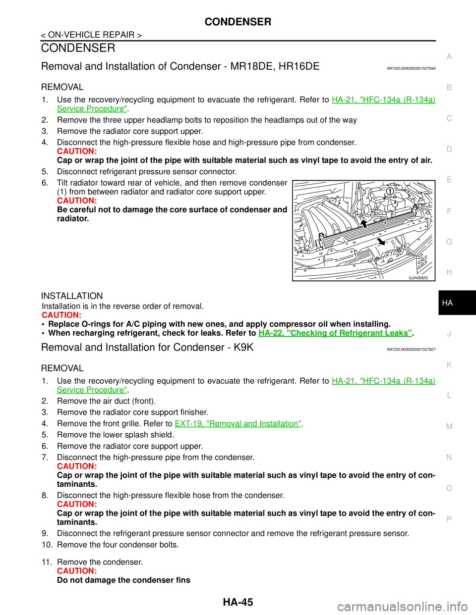
6. Tilt radiator toward rear of vehicle, and then remove condenser
(1) from between radiator and radiator core support upper.
CAUTION:
Be careful not to damage the core surface of condenser and
radiator.
INSTALLATION
Installation is in the reverse order of removal.
CAUTION:
Replace O-rings for A/C piping with new ones, and apply compressor oil when installing.
When recharging refrigerant, check for leaks. Refer to HA-22, "
Checking of Refrigerant Leaks".
Removal and Installation for Condenser - K9KINFOID:0000000001527627
REMOVAL
1. Use the recovery/recycling equipment to evacuate the refrigerant. Refer to HA-21, "HFC-134a (R-134a)
Service Procedure".
2. Remove the air duct (front).
3. Remove the radiator core support finisher.
4. Remove the front grille. Refer to EXT-19, "
Removal and Installation".
5. Remove the lower splash shield.
6. Remove the radiator core support upper.
7. Disconnect the high-pressure pipe from the condenser.
CAUTION:
Cap or wrap the joint of the pipe with suitable material such as vinyl tape to avoid the entry of con-
taminants.
8. Disconnect the high-pressure flexible hose from the condenser.
CAUTION:
Cap or wrap the joint of the pipe with suitable material such as vinyl tape to avoid the entry of con-
taminants.
9. Disconnect the refrigerant pressure sensor connector and remove the refrigerant pressure sensor.
10. Remove the four condenser bolts.
11. Remove the condenser.
CAUTION:
Do not damage the condenser fins
SJIA0682E
Page 3330 of 5883

HA-48
< ON-VEHICLE REPAIR >
REFRIGERANT PRESSURE SENSOR
REFRIGERANT PRESSURE SENSOR
Removal and Installation of Refrigerant Pressure Sensor - MR18DE, HR16DE
INFOID:0000000001527644
REMOVAL
1. Use the recovery/recycling equipment to evacuate the refrigerant. Refer to HA-21, "HFC-134a (R-134a)
Service Procedure".
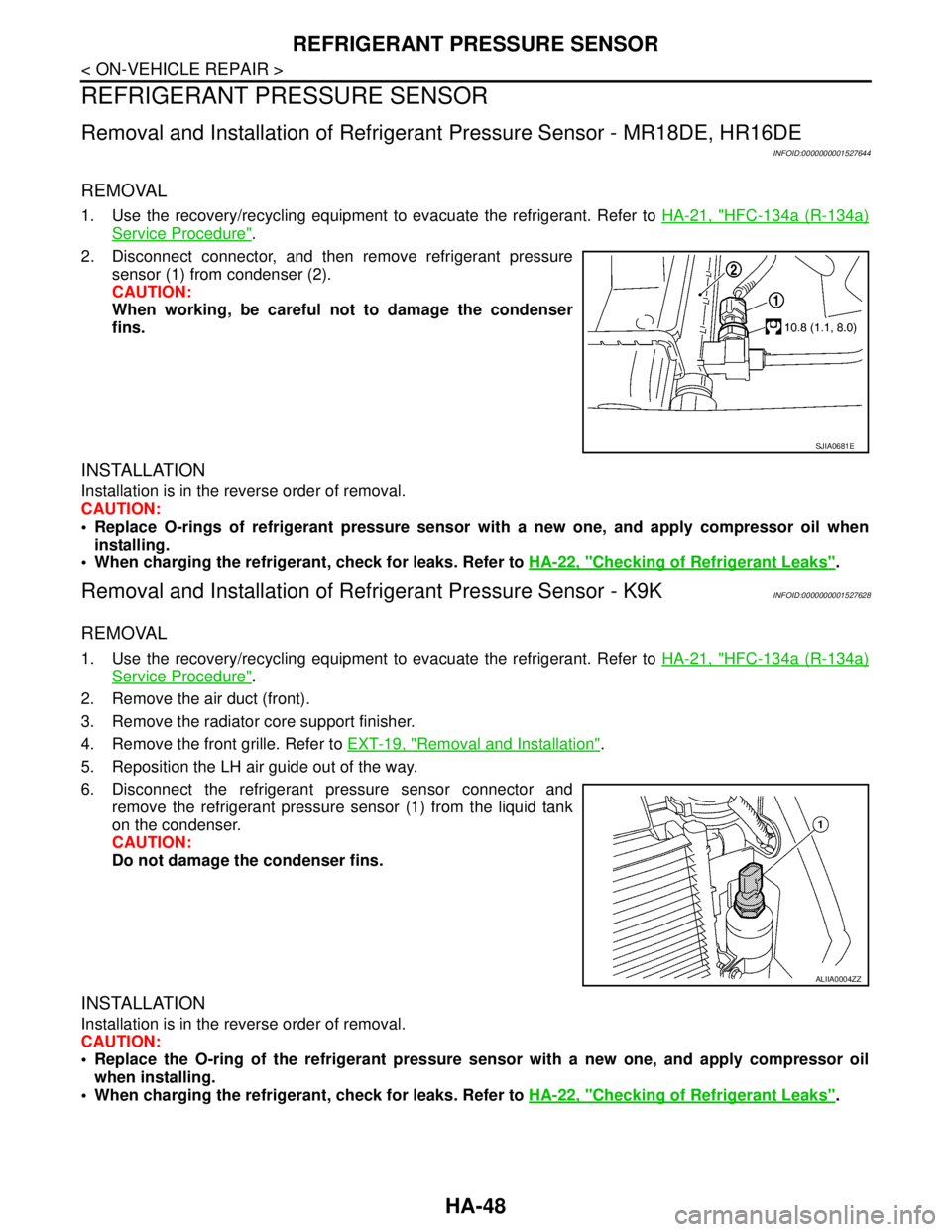
2. Disconnect connector, and then remove refrigerant pressure
sensor (1) from condenser (2).
CAUTION:
When working, be careful not to damage the condenser
fins.
INSTALLATION
Installation is in the reverse order of removal.
CAUTION:
Replace O-rings of refrigerant pressure sensor with a new one, and apply compressor oil when
installing.
When charging the refrigerant, check for leaks. Refer to HA-22, "
Checking of Refrigerant Leaks".
Removal and Installation of Refrigerant Pressure Sensor - K9KINFOID:0000000001527628
REMOVAL
1. Use the recovery/recycling equipment to evacuate the refrigerant. Refer to HA-21, "HFC-134a (R-134a)
Service Procedure".
2. Remove the air duct (front).
3. Remove the radiator core support finisher.
4. Remove the front grille. Refer to EXT-19, "
Removal and Installation".
5. Reposition the LH air guide out of the way.
6. Disconnect the refrigerant pressure sensor connector and
remove the refrigerant pressure sensor (1) from the liquid tank
on the condenser.
CAUTION:
Do not damage the condenser fins.
INSTALLATION
Installation is in the reverse order of removal.
CAUTION:
Replace the O-ring of the refrigerant pressure sensor with a new one, and apply compressor oil
when installing.
When charging the refrigerant, check for leaks. Refer to HA-22, "
Checking of Refrigerant Leaks".
SJIA0681E
ALIIA0004ZZ
Page 3367 of 5883
![NISSAN TIIDA 2007 Service Repair Manual HAC-34
< COMPONENT DIAGNOSIS >[MANUAL AIR CONDITIONER]
PTC HEATER CONTROL SYSTEM
PTC HEATER (300 WATT) : PTC Heater Component Description
INFOID:0000000001674172
COMPONENT DESCRIPTION
PTC Control Unit NISSAN TIIDA 2007 Service Repair Manual HAC-34
< COMPONENT DIAGNOSIS >[MANUAL AIR CONDITIONER]
PTC HEATER CONTROL SYSTEM
PTC HEATER (300 WATT) : PTC Heater Component Description
INFOID:0000000001674172
COMPONENT DESCRIPTION
PTC Control Unit](/manual-img/5/57395/w960_57395-3366.png)
HAC-34
< COMPONENT DIAGNOSIS >[MANUAL AIR CONDITIONER]
PTC HEATER CONTROL SYSTEM
PTC HEATER (300 WATT) : PTC Heater Component Description
INFOID:0000000001674172
COMPONENT DESCRIPTION
PTC Control Unit
The PTC control unit is attached on the A/C unit assembly. It controls
PTC heater by ambient temperature, water temperature, FAN ON
signal and temperature control dial.
PTC Heater
The PTC heater is attached on the A/C unit assembly. It generates
heat electrically.
Ambient Sensor
The ambient sensor is attached on the radiator core support upper. It
detects ambient temperature and converts it into a resistance value
which is then input into the PTC control unit.
Water Temperature Sensor
The water temperature sensor is attached on heater pipe. It detects
water temperature and converts it into a resistance value which is
then input in to PTC control unit.
Full Hot Switch
SJIA0906E
SJIA0907E
AWIIA0600ZZ
SJIA0908E
Page 3378 of 5883
![NISSAN TIIDA 2007 Service Repair Manual PTC HEATER CONTROL SYSTEM
HAC-45
< COMPONENT DIAGNOSIS >[MANUAL AIR CONDITIONER]
C
D
E
F
G
H
J
K
L
MA
B
HAC
N
O
P
The PTC control unit is attached on the A/C unit assembly. It controls
PTC heater by a NISSAN TIIDA 2007 Service Repair Manual PTC HEATER CONTROL SYSTEM
HAC-45
< COMPONENT DIAGNOSIS >[MANUAL AIR CONDITIONER]
C
D
E
F
G
H
J
K
L
MA
B
HAC
N
O
P
The PTC control unit is attached on the A/C unit assembly. It controls
PTC heater by a](/manual-img/5/57395/w960_57395-3377.png)
PTC HEATER CONTROL SYSTEM
HAC-45
< COMPONENT DIAGNOSIS >[MANUAL AIR CONDITIONER]
C
D
E
F
G
H
J
K
L
MA
B
HAC
N
O
P
The PTC control unit is attached on the A/C unit assembly. It controls
PTC heater by ambient temperature, and FAN ON signal.
PTC Heater
The PTC heater is attached on the A/C unit assembly. It generates
heat electrically.
Ambient Sensor
The ambient sensor is attached on the radiator core support upper. It
detects ambient temperature and converts it into a resistance value
which is then input into the PTC control unit.
PTC HEATER (1500 WATT) : PTC Heater (1500 Watt) Diagnosis Procedure
INFOID:0000000001682732
DIAGNOSTIC PROCEDURE FOR PTC SYSTEM
SYMPTOM: PTC heater system operation is malfunction.
1.CHECK POWER SUPPLY FOR BLOWER RELAY
1. Turn ignition switch ON.
2. Disconnect blower relay.
3. Check voltage between blower relay harness connector J-1 ter-
minals 1, 5, and ground.
Is the inspection result normal
YES >> GO TO 2.
NO >> Repair harness or connector.
SJIA0906E
ALIIA0132ZZ
AWIIA0600ZZ
Te r m i n a l s
Vo l ta g e
(Approx.)
(+) (−)
Connector Terminal
Ground Battery voltage
Blower relay: J-11
5
WJIA1783E
Page 3414 of 5883
![NISSAN TIIDA 2007 Service Repair Manual INSUFFICIENT HEATING
HAC-81
< SYMPTOM DIAGNOSIS >[MANUAL AIR CONDITIONER]
C
D
E
F
G
H
J
K
L
MA
B
HAC
N
O
P
INSUFFICIENT HEATING
Component Function CheckINFOID:0000000001547078
SYMPTOM: Insufficient he NISSAN TIIDA 2007 Service Repair Manual INSUFFICIENT HEATING
HAC-81
< SYMPTOM DIAGNOSIS >[MANUAL AIR CONDITIONER]
C
D
E
F
G
H
J
K
L
MA
B
HAC
N
O
P
INSUFFICIENT HEATING
Component Function CheckINFOID:0000000001547078
SYMPTOM: Insufficient he](/manual-img/5/57395/w960_57395-3413.png)
INSUFFICIENT HEATING
HAC-81
< SYMPTOM DIAGNOSIS >[MANUAL AIR CONDITIONER]
C
D
E
F
G
H
J
K
L
MA
B
HAC
N
O
P
INSUFFICIENT HEATING
Component Function CheckINFOID:0000000001547078
SYMPTOM: Insufficient heating
INSPECTION FLOW
1.CONFIRM SYMPTOM BY PERFORMING OPERATIONAL CHECK - TEMPERATURE DECREASE
1. Turn temperature control dial clockwise to maximum heat position.
2. Check for hot air at discharge air outlets.
Can the symptom be duplicated?
YES >> GO TO 3.
NO >> GO TO 2.
2.CHECK FOR ANY SYMPTOMS
Perform a complete operational check for any symptoms. Refer to HAC-6, "
Operational Check".
Does another symptom exist?
YES >> Refer to HAC-5, "How to Perform Trouble Diagnosis For Quick and Accurate Repair" .
NO >> System OK.
3.CHECK FOR SERVICE BULLETINS
Check for any service bulletins.
>> GO TO 4.
4.CHECK COOLANT SYSTEM
1. Check engine coolant level. Refer to XX-XX, "*****" .
2. Check hoses for leaks or kinks.
3. Check Radiator cap. Refer to XX-XX, "*****" .
OK or NG
OK >> GO TO 5.
NG >> Repair/replace as necessary.
5.CHECK AIR MIX DOOR CABLE
Check air mix door cable operation. Refer to XXXX AIR MIX DOOR CABLE ADJUSTMENT .
OK or NG
YES >> GO TO 6.
NO >> Adjust or replace air mix door cable. Refer to XXXX AIR MIX DOOR CABLE ADJUST. .
6.CHECK AIR DUCTS
Check ducts for air leaks.
OK or NG
OK >> GO TO 7.
NG >> Repair air leaks.
7.CHECK HEATER HOSE TEMPERATURES
1. Start engine and warm it up to normal operating temperature.
2. Touch both the inlet and outlet heater hoses.
Is the inlet hose hot and the outlet hose warm?
YES >> GO TO 8.
NO >> Both hoses warm: GO TO 9.
8.CHECK ENGINE COOLANT TEMPERATURE SENSOR
Check engine control temperature sensor. Refer to XX-XX, "*****" .
OK or NG
OK >> System OK.