Page 606 of 2896

INTELLIGENT KEY SYSTEM
BL-117
C
D
E
F
G
H
J
K
L
MA
B
BL
Revision: June 20062007 Versa
Symptom Diagnosis/service procedure Reference page
Door lock/unlock do not operate by all request
switch.1. Check door switch.BL-129
2. Check key switch.BL-124
3. Check ignition knob switch.BL-127
4. Replace Intelligent Key unit.BL-160
Door lock/unlock does not operate by request
switch (driver side).1. Check door request switch (driver side).BL-1322. Check outside key antenna (driver side).BL-139
3. Replace Intelligent Key unit.BL-160
Door lock/unlock does not operate by request
switch (passenger side).1. Check door request switch (passenger side).BL-1322. Check outside key antenna (passenger side).BL-139
3. Replace Intelligent Key unit.BL-160
Door lock/unlock does not operate by back door
request switch.1. Check back door request switch.BL-1342. Check outside key antenna (rear bumper).BL-141
3. Replace Intelligent Key unit.BL-160
Auto lock function does not operate.1.Check “AUTO RELOCK TIMER” setting in “WORK
SUPPORT”.BL-113
2. Replace Intelligent Key unit.BL-160
Key reminder function does not operate.1. Check door switch.BL-129
2. Check inside key antenna.BL-143
3. Check unlock sensor.BL-136
4. Check Intelligent Key battery.BL-159
5. Replace Intelligent Key unit.BL-160
Page 607 of 2896

BL-118
INTELLIGENT KEY SYSTEM
Revision: June 20062007 Versa
REMOTE KEYLESS ENTRY FUNCTION MALFUNCTION
NOTE:
�Before performing the diagnosis in the following table, check “Trouble Diagnosis Procedure”. Refer to BL-
109, "Trouble Diagnosis Procedure" .
�Make sure that vehicle is under the condition shown in “Conditions of vehicle” before starting diagnosis,
and check each symptom.
�If the following “symptoms” are detected, check systems shown in the “Diagnosis/service procedure” col-
umn in this order.
Conditions of Vehicle (Operating Conditions)
�Ignition switch is not depressed.
�All doors are closed.
Symptom Diagnosis/service procedureReference
page
All of the remote keyless entry functions
do not operate.1. Check Intelligent Key unit power supply and ground circuit.BL-123
2. Check key switch (BCM input).BL-126
3. Check Intelligent Key battery.BL-159
4. Remote Keyless Entry function inspection.BL-159
5. Replace Intelligent Key unit.BL-160
Auto lock function does not operate.1. Check “AUTO RELOCK TIMER” setting in “WORK SUPPORT”.BL-1132. Replace Intelligent Key unit.BL-160
Key reminder function does not operate.1. Check door switch.BL-129
2. Check inside key antenna.BL-143
3. Check unlock sensor.BL-136
4. Check Intelligent Key battery.BL-159
5. Replace Intelligent Key unit.BL-160
Panic alarm function does not operate.1. Check “PANIC ALARM DELAY” setting in “WORK SUPPORT”.BL-113
2. Check Intelligent Key battery inspection.BL-159
3. Check horn function.BL-157
4. Check headlamp function.BL-158
5. Check key switch.BL-124
6. Check ignition knob switch.BL-127
7. Replace Intelligent Key unit.BL-160
Page 625 of 2896

BL-136
INTELLIGENT KEY SYSTEM
Revision: June 20062007 Versa
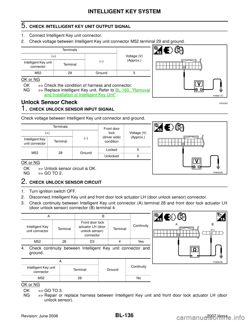
5. CHECK INTELLIGENT KEY UNIT OUTPUT SIGNAL
1. Connect Intelligent Key unit connector.
2. Check voltage between Intelligent Key unit connector M52 terminal 29 and ground.
OK or NG
OK >> Check the condition of harness and connector.
NG >> Replace Intelligent Key unit. Refer to BL-160, "
Removal
and Installation of Intelligent Key Unit" .
Unlock Sensor CheckEIS0092I
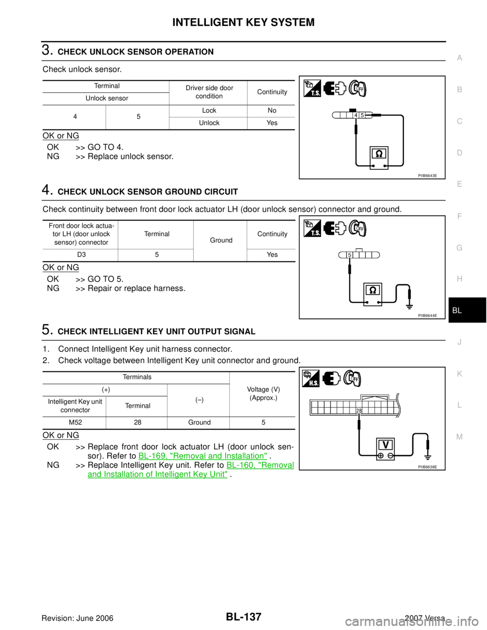
1. CHECK UNLOCK SENSOR INPUT SIGNAL
Check voltage between Intelligent Key unit connector and ground.
OK or NG
OK >> Unlock sensor circuit is OK.
NG >> GO TO 2.
2. CHECK UNLOCK SENSOR CIRCUIT
1. Turn ignition switch OFF.
2. Disconnect Intelligent Key unit and front door lock actuator LH (door unlock sensor) connector.
3. Check continuity between Intelligent Key unit connector (A) terminal 28 and front door lock actuator LH
(door unlock sensor) connector (B) terminal 4.
4. Check continuity between Intelligent Key unit connector and
ground.
OK or NG
OK >> GO TO 3.
NG >> Repair or replace harness between Intelligent Key unit and front door lock actuator LH (door
unlock sensor).
Te r m i n a l s
Voltage (V)
(Approx.) (+)
(–)
Intelligent Key unit
connectorTerminal
M52 29 Ground 5
PIIB6617E
Te r m i n a l s
Front door
lock
(driver side)
conditionVoltage (V)
(Approx.) (+)
(–)
Intelligent Key
unit connectorTerminal
M52 28 GroundLocked 5
Unlocked 0
PIIB6638E
AB
Continuity
Intelligent Key
unit connectorTe r m i n a l Front door lock
actuator LH (door
unlock sensor)
connectorTe r m i n a l
M52 28 D3 4 Yes
A
GroundContinuity
Intelligent Key unit
connectorTe r m i n a l
M52 28 No
PIIB6639E
Page 626 of 2896

INTELLIGENT KEY SYSTEM
BL-137
C
D
E
F
G
H
J
K
L
MA
B
BL
Revision: June 20062007 Versa
3. CHECK UNLOCK SENSOR OPERATION
Check unlock sensor.
OK or NG
OK >> GO TO 4.
NG >> Replace unlock sensor.
4. CHECK UNLOCK SENSOR GROUND CIRCUIT
Check continuity between front door lock actuator LH (door unlock sensor) connector and ground.
OK or NG
OK >> GO TO 5.
NG >> Repair or replace harness.
5. CHECK INTELLIGENT KEY UNIT OUTPUT SIGNAL
1. Connect Intelligent Key unit harness connector.
2. Check voltage between Intelligent Key unit connector and ground.
OK or NG
OK >> Replace front door lock actuator LH (door unlock sen-
sor). Refer to BL-169, "
Removal and Installation" .
NG >> Replace Intelligent Key unit. Refer to BL-160, "
Removal
and Installation of Intelligent Key Unit" .
Terminal
Driver side door
conditionContinuity
Unlock sensor
45Lock No
Unlock Yes
PIIB6643E
Front door lock actua-
tor LH (door unlock
sensor) connectorTe r m i n a l
GroundContinuity
D3 5 Yes
PIIB6644E
Te r m i n a l s
Voltage (V)
(Approx.) (+)
(–)
Intelligent Key unit
connectorTe r m i n a l
M52 28 Ground 5
PIIB6638E
Page 664 of 2896
BACK DOOR LOCK
BL-175
C
D
E
F
G
H
J
K
L
MA
B
BL
Revision: June 20062007 Versa
BACK DOOR LOCKPFP:90504
Component Parts and Harness Connector LocationEIS009DK
LIIA2638E
1. BCM M18, M19, M20
(view with glove box removed)2. Intelligent Key unit M52
(if equipped)3. Back door lock assembly (actuator)
D405
4. Back door opener switch D408 5. Front door lock actuator (door
unlock sensor) LH D3, RH D114
Page 665 of 2896

BL-176
BACK DOOR LOCK
Revision: June 20062007 Versa
System DescriptionEIS0 09 DL
Power is supplied at all times
�through 40A fusible link (letter g, located in fuse and fusible link box)
�to BCM terminal 70
�through 10A fuse [No. 8, located in fuse block (J/B)]
�to BCM terminal 57
�through 10A fuse [No. 31, located in fuse block (J/B)]
�to Intelligent Key unit terminal 11 (if equipped).
Ground is supplied
�to BCM terminal 67 and
�to Intelligent Key unit terminal 12 (if equipped)
�through body grounds M57 and M61.
When back door opener switch is ON (pushed), ground is supplied
�to BCM terminal 30 (without Intelligent Key)
�through back door opener switch terminals 1 and 2
�through front door lock actuator LH (door unlock sensor) terminals 4 and 5 (without power windows) or
�through front door lock actuator RH (door unlock sensor) terminals 4 and 5 (with power windows)
�through body grounds M57 and M61
�to Intelligent Key unit terminal 24 (if equipped)
�through back door opener switch terminals 1 and 2
�through body grounds B117, B132 and D402.
Then power is supplied
�through BCM terminal 53
�to back door lock assembly (actuator) terminal 1.
Ground is supplied
�to back door lock assembly (actuator) terminal 2
�through body grounds B117, B132 and D402.
Then BCM operates back door lock assembly (actuator).
Page 671 of 2896

BL-182
BACK DOOR LOCK
Revision: June 20062007 Versa
3. CHECK BACK DOOR OPENER SWITCH
Check continuity between back door opener switch terminals 1 and 2.
OK or NG
OK >> GO TO 4.
NG >> Replace back door opener switch.
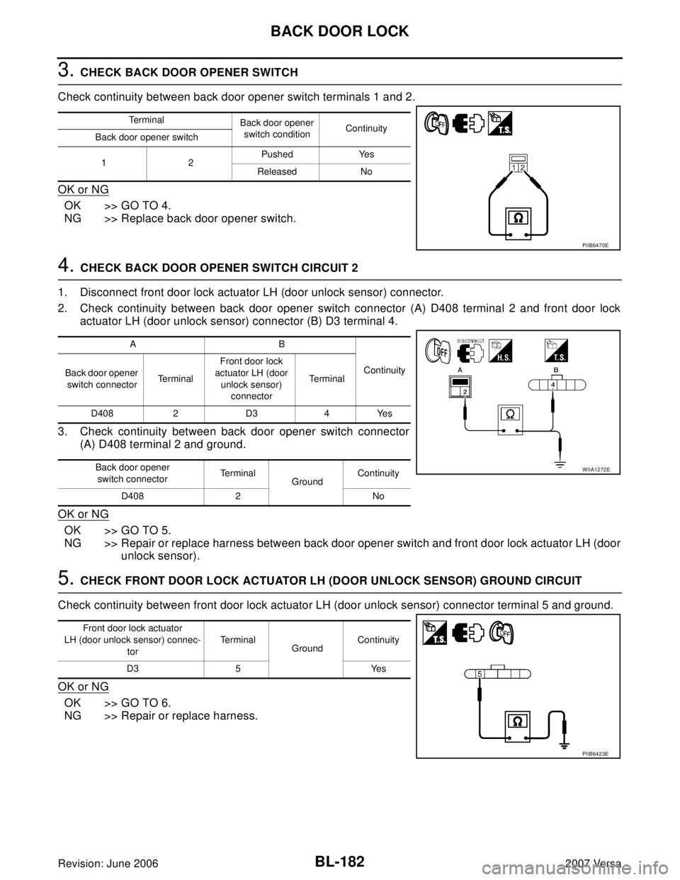
4. CHECK BACK DOOR OPENER SWITCH CIRCUIT 2
1. Disconnect front door lock actuator LH (door unlock sensor) connector.
2. Check continuity between back door opener switch connector (A) D408 terminal 2 and front door lock
actuator LH (door unlock sensor) connector (B) D3 terminal 4.
3. Check continuity between back door opener switch connector
(A) D408 terminal 2 and ground.
OK or NG
OK >> GO TO 5.
NG >> Repair or replace harness between back door opener switch and front door lock actuator LH (door
unlock sensor).
5. CHECK FRONT DOOR LOCK ACTUATOR LH (DOOR UNLOCK SENSOR) GROUND CIRCUIT
Check continuity between front door lock actuator LH (door unlock sensor) connector terminal 5 and ground.
OK or NG
OK >> GO TO 6.
NG >> Repair or replace harness.
Te r m i n a l
Back door opener
switch conditionContinuity
Back door opener switch
12Pushed Yes
Released No
PIIB6470E
AB
Continuity
Back door opener
switch connectorTe r m i n a lFront door lock
actuator LH (door
unlock sensor)
connectorTe r m i n a l
D408 2 D3 4 Yes
Back door opener
switch connectorTe r m i n a l
GroundContinuity
D408 2 No
WIIA1272E
Front door lock actuator
LH (door unlock sensor) connec-
torTe r m i n a l
GroundContinuity
D3 5 Yes
PIIB6423E
Page 672 of 2896
BACK DOOR LOCK
BL-183
C
D
E
F
G
H
J
K
L
MA
B
BL
Revision: June 20062007 Versa
6. CHECK UNLOCK SENSOR FUNCTION
1. Connect front door lock actuator LH (door unlock sensor) connector.
2. Check continuity between back door opener switch connector D408 terminal 2 and ground.
OK or NG
OK >> GO TO 7.
NG >> Replace front door lock actuator LH (door unlock sen-
sor). Refer to BL-169, "
FRONT DOOR LOCK" .
7. CHECK BACK DOOR OPENER SWITCH SIGNAL 2
1. Connect BCM connector.
2. Check voltage between BCM connector M18 terminal 30 and ground.
OK or NG
OK >> Check the condition of harness and connector.
NG >> Replace BCM. Refer to BCS-25, "
Removal and Installa-
tion of BCM" .
Back door
opener switch
connectorTe r m i n a lFront door lock
knob LH positionContinuity
D408 2 GroundUnlock Yes
Lock No
PIIB6472E
Te r m i n a l s
Voltage (V)
(Approx.) (+)
(–)
BCM connector Terminal
M18 30 Ground Battery voltage
PIIB6468E