Page 674 of 2896

BACK DOOR LOCK
BL-185
C
D
E
F
G
H
J
K
L
MA
B
BL
Revision: June 20062007 Versa
3. CHECK BACK DOOR OPENER SWITCH
Check continuity between back door opener switch terminals 1 and 2.
OK or NG
OK >> GO TO 4.
NG >> Replace back door opener switch.
4. CHECK BACK DOOR OPENER SWITCH CIRCUIT 2
1. Disconnect front door lock actuator RH (door unlock sensor) connector.
2. Check continuity between back door opener switch connector (A) D408 terminal 2 and front door lock
actuator RH (door unlock sensor) connector (B) D114 terminal 4.
3. Check continuity between back door opener switch connector
(A) D408 terminal 2 and ground.
OK or NG
OK >> GO TO 5.
NG >> Repair or replace harness between back door opener switch and front door lock actuator RH
(door unlock sensor).
5. CHECK FRONT DOOR LOCK ACTUATOR RH (DOOR UNLOCK SENSOR) GROUND CIRCUIT
Check continuity between front door lock actuator RH (door unlock sensor) connector terminal 5 and ground.
OK or NG
OK >> GO TO 6.
NG >> Repair or replace harness.
Terminal
Back door opener
switch conditionContinuity
Back door opener switch
12Pushed Yes
Released No
PIIB6470E
AB
Continuity
Back door opener
switch connectorTe r m i n a lFront door lock
actuator RH (door
unlock sensor)
connectorTe r m i n a l
D408 2 D114 4 Yes
Back door opener
switch connectorTe r m i n a l
GroundContinuity
D408 2 No
WIIA1271E
Front door lock actuator
RH (door unlock sensor) con-
nectorTe r m i n a l
GroundContinuity
D114 5 Yes
WIIA1273E
Page 675 of 2896
BL-186
BACK DOOR LOCK
Revision: June 20062007 Versa
6. CHECK UNLOCK SENSOR FUNCTION
1. Connect front door lock actuator RH (door unlock sensor) connector.
2. Check continuity between back door opener switch connector D408 terminal 2 and ground.
OK or NG
OK >> GO TO 7.
NG >> Replace front door lock actuator RH (door unlock sen-
sor). Refer to BL-169, "
FRONT DOOR LOCK" .
7. CHECK BACK DOOR OPENER SWITCH SIGNAL 2
1. Connect BCM connector.
2. Check voltage between BCM connector and ground.
OK or NG
OK >> Check the condition of harness and connector.
NG >> Replace BCM. Refer to BCS-25, "
Removal and Installa-
tion of BCM" .
Back door
opener switch
connectorTe r m i n a lFront door lock
knob RH positionContinuity
D408 2 GroundUnlock Yes
Lock No
PIIB6472E
Te r m i n a l s
Voltage (V)
(Approx.) (+)
(–)
BCM connector Terminal
M18 30 Ground Battery voltage
PIIB6468E
Page 791 of 2896

BR-8
BRAKE PEDAL
Revision: June 20062007 Versa
REMOVAL
1. Disconnect accelerator pedal position sensor harness connec-
tor.
2. Remove stop lamp switch from brake pedal assembly.
3. Remove snap pin and clevis pin from clevis of brake booster.
4. Remove nuts from brake pedal bracket, and remove brake pedal
assembly from vehicle.
5. Remove accelerator pedal from brake pedal assembly.
INSPECTION AFTER REMOVAL
�Check brake pedal upper rivet for deformation.
�Make sure that the lapping length of sub-bracket and slide plate
is at least 6.9 mm (0.272 in).
�Check brake pedal for bend, damage, and cracks on the welded
parts.
�Replace brake pedal assembly if any non-standard condition is
detected.
�Check clevis pin and plastic stopper for damage and deforma-
tion. Replace clevis pin as necessary.
INSTALLATION
Installation is in the reverse order of the removal.
�After installing brake pedal assembly to vehicle, adjust brake pedal. Refer to BR-7, "ADJUSTMENT" .
�After installing accelerator pedal, check accelerator pedal. Refer to ACC-3, "INSPECTION AFTER
INSTALLATION" .
SFIA2044E
SFIA2866E
SBR9 97
Page 807 of 2896
BR-24
FRONT DISC BRAKE
Revision: June 20062007 Versa
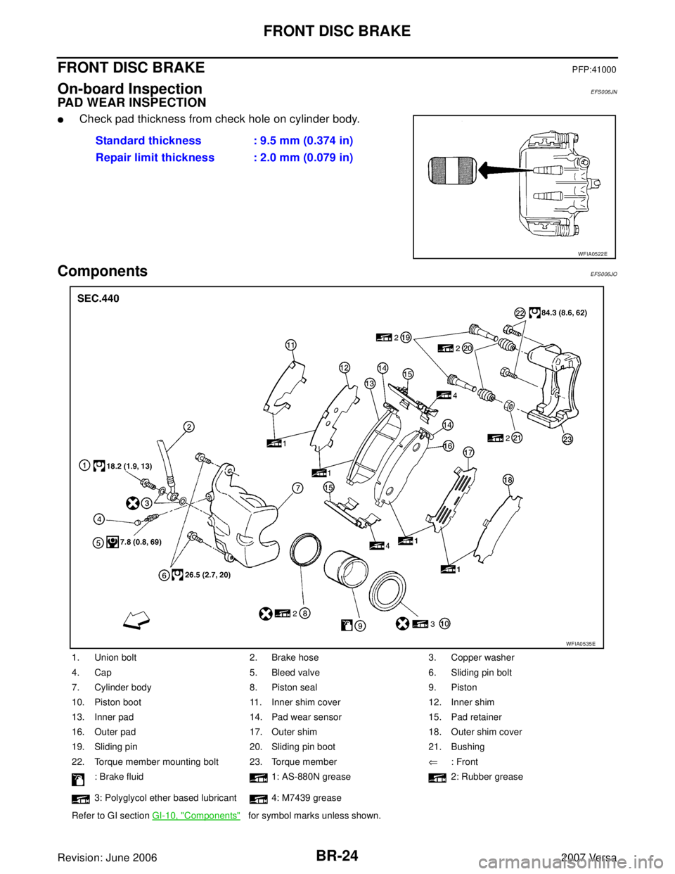
FRONT DISC BRAKEPFP:41000
On-board InspectionEFS006JN
PAD WEAR INSPECTION
�Check pad thickness from check hole on cylinder body.
ComponentsEFS006JO
Standard thickness : 9.5 mm (0.374 in)
Repair limit thickness : 2.0 mm (0.079 in)
WFIA0522E
1. Union bolt 2. Brake hose 3. Copper washer
4. Cap 5. Bleed valve 6. Sliding pin bolt
7. Cylinder body 8. Piston seal 9. Piston
10. Piston boot 11. Inner shim cover 12. Inner shim
13. Inner pad 14. Pad wear sensor 15. Pad retainer
16. Outer pad 17. Outer shim 18. Outer shim cover
19. Sliding pin 20. Sliding pin boot 21. Bushing
22. Torque member mounting bolt 23. Torque member⇐: Front
: Brake fluid 1: AS-880N grease 2: Rubber grease
3: Polyglycol ether based lubricant 4: M7439 grease
Refer to GI section GI-10, "
Components" for symbol marks unless shown.
WFIA0535E
Page 820 of 2896

BRC-1
BRAKE CONTROL SYSTEM
F BRAKES
CONTENTS
C
D
E
G
H
I
J
K
L
M
SECTION BRC
A
B
BRC
Revision: June 20062007 VersaABS
PRECAUTIONS .......................................................... 2
Precautions for Supplemental Restraint System
(SRS) “AIR BAG” and “SEAT BELT PRE-TEN-
SIONER” .................................................................. 2
Precautions for Brake System .................................. 2
Precautions When Using CONSULT-II ..................... 2
CHECK POINTS FOR USING CONSULT-II ......... 2
Precautions for Brake Control .................................. 3
Precautions for CAN System ................................... 3
PREPARATION ........................................................... 4
Special Service Tools ............................................... 4
Commercial Service Tools ........................................ 4
SYSTEM DESCRIPTION ............................................ 5
System Components ................................................ 5
ABS Function ........................................................... 5
EBD Function ........................................................... 5
Fail-Safe Function .................................................... 6
ABS/EBD SYSTEM ............................................... 6
Hydraulic Circuit Diagram ........................................ 6
CAN COMMUNICATION ............................................ 7
System Description .................................................. 7
TROUBLE DIAGNOSIS .............................................. 8
How to Perform Trouble Diagnoses for Quick and
Accurate Repair ....................................................... 8
INTRODUCTION ................................................... 8
WORK FLOW ........................................................ 9
CLARIFY CONCERN .......................................... 10
EXAMPLE OF DIAGNOSIS SHEET ................... 10
Component Parts and Harness Connector Location ....11
Schematic .............................................................. 12
Wiring Diagram — ABS — ..................................... 13
Basic Inspection ..................................................... 17
BRAKE FLUID LEVEL, FLUID LEAK, AND
BRAKE PAD INSPECTION ................................. 17
POWER SYSTEM TERMINAL LOOSENESS AND BATTERY INSPECTION ............................. 17
ABS WARNING LAMP INSPECTION ................. 17
Warning Lamp and Indicator Timing ....................... 18
Control Unit Input/Output Signal Standard ............. 18
REFERENCE VALUE FROM CONSULT-II ......... 18
CONSULT-II Function (ABS) .................................. 20
CONSULT-II START PROCEDURE .................... 20
SELF-DIAGNOSIS .............................................. 20
DATA MONITOR ................................................. 22
ACTIVE TEST ..................................................... 24
TROUBLE DIAGNOSIS FOR SELF-DIAGNOSTIC
ITEMS ........................................................................ 25
Wheel Sensor System ............................................ 25
ABS Control Unit Inspection ................................... 26
Solenoid Valve System Inspection ......................... 27
Actuator Motor, Motor Relay, and Circuit Inspection ... 28
ABS Control Unit Power and Ground Systems
Inspection ............................................................... 29
CAN Communication System Inspection ................ 29
TROUBLE DIAGNOSES FOR SYMPTOMS ............ 30
ABS Works Frequently ........................................... 30
Unexpected Pedal Action ....................................... 31
Long Stopping Distance .......................................... 32
ABS Does Not Work ............................................... 32
Pedal Vibration or ABS Operation Noise ................ 32
WHEEL SENSORS ................................................... 33
Removal and Installation ........................................ 33
REMOVAL ........................................................... 33
INSTALLATION ................................................... 33
SENSOR ROTOR ..................................................... 35
Removal and Installation ........................................ 35
ACTUATOR AND ELECTRIC UNIT (ASSEMBLY) ... 36
Removal and Installation ........................................ 36
REMOVAL ........................................................... 36
INSTALLATION ................................................... 37
Page 823 of 2896
BRC-4
[ABS]
PREPARATION
Revision: June 20062007 Versa
PREPARATIONPFP:00002
Special Service ToolsEFS006M7
The actual shapes of Kent-Moore tools may differ from those of special service tools illustrated here.
Commercial Service ToolsEFS006M8
Tool number
(Kent-Moore No.)
Tool nameDescription
KV991J0080
(J-45741)
ABS active wheel sensor testerChecking operation of ABS active wheel sen-
sors
WFIA0101E
Tool nameDescription
1. Flare nut crowfoot
2. Torque wrenchRemoving and installing brake piping
a: 10 mm (0.39 in)/12 mm (0.47 in)
S-NT360
Page 827 of 2896
![NISSAN LATIO 2007 Service Repair Manual BRC-8
[ABS]
TROUBLE DIAGNOSIS
Revision: June 20062007 Versa
TROUBLE DIAGNOSISPFP:00000
How to Perform Trouble Diagnoses for Quick and Accurate RepairEFS006LI
INTRODUCTION
The ABS system has an electro](/manual-img/5/57361/w960_57361-826.png "NISSAN LATIO 2007 Service Repair Manual BRC-8
[ABS]
TROUBLE DIAGNOSIS
Revision: June 20062007 Versa
TROUBLE DIAGNOSISPFP:00000
How to Perform Trouble Diagnoses for Quick and Accurate RepairEFS006LI
INTRODUCTION
The ABS system has an electro")
BRC-8
[ABS]
TROUBLE DIAGNOSIS
Revision: June 20062007 Versa
TROUBLE DIAGNOSISPFP:00000
How to Perform Trouble Diagnoses for Quick and Accurate RepairEFS006LI
INTRODUCTION
The ABS system has an electronic control unit to control major func-
tions. The control unit accepts input signals from sensors and con-
trols actuator operation. It is also important to check for air leaks in
the booster or brake and vacuum lines, lack of brake fluid, or other
malfunctions in the brake system.
It is much more difficult to diagnose a malfunction that occurs inter-
mittently rather than continuously. Most intermittent conditions are
caused by poor electrical connections or damaged wiring. In this
case, careful checking of suspicious circuits may help prevent the
replacement of good parts.
A visual check only may not find the cause of the malfunction, so a
road test should be performed.
Before undertaking actual checks, take just a few minutes to talk with
a customer who approaches with an ABS complaint. The customer
is a very good source of information, especially for intermittent condi-
tions. Through the talks with the customer, find out what symptoms
are present and under what conditions they occur.
Start your diagnosis by looking for “conventional” malfunctions first.
This is one of the best ways to troubleshoot brake malfunctions on
an ABS equipped vehicle. Also check related Service Bulletins for
information.
SEF 2 33 G
SEF 2 34 G
Page 830 of 2896
TROUBLE DIAGNOSIS
BRC-11
[ABS]
C
D
E
G
H
I
J
K
L
MA
B
BRC
Revision: June 20062007 Versa
Component Parts and Harness Connector LocationEFS006LJ
1. Front wheel sensor
LH E51
RH E522. Rear wheel sensor
LH B123
RH B1243. ABS actuator and electric unit (con-
trol unit) E33
4. Combination meter M24
WFIA0497E
 connector.
2. Check continuity between back door opener")
![NISSAN LATIO 2007 Service Repair Manual BRC-4
[ABS]
PREPARATION
Revision: June 20062007 Versa
PREPARATIONPFP:00002
Special Service ToolsEFS006M7
The actual shapes of Kent-Moore tools may differ from those of special service tools illustrate](/manual-img/5/57361/w960_57361-822.png "NISSAN LATIO 2007 Service Repair Manual BRC-4
[ABS]
PREPARATION
Revision: June 20062007 Versa
PREPARATIONPFP:00002
Special Service ToolsEFS006M7
The actual shapes of Kent-Moore tools may differ from those of special service tools illustrate")
![NISSAN LATIO 2007 Service Repair Manual TROUBLE DIAGNOSIS
BRC-11
[ABS]
C
D
E
G
H
I
J
K
L
MA
B
BRC
Revision: June 20062007 Versa
Component Parts and Harness Connector LocationEFS006LJ
1. Front wheel sensor
LH E51
RH E522. Rear wheel sensor
L](/manual-img/5/57361/w960_57361-829.png "NISSAN LATIO 2007 Service Repair Manual TROUBLE DIAGNOSIS
BRC-11
[ABS]
C
D
E
G
H
I
J
K
L
MA
B
BRC
Revision: June 20062007 Versa
Component Parts and Harness Connector LocationEFS006LJ
1. Front wheel sensor
LH E51
RH E522. Rear wheel sensor
L")