Page 2838 of 2896

WT-20
TROUBLE DIAGNOSIS FOR SELF-DIAGNOSTIC ITEMS
Revision: June 20062007 Versa
TROUBLE DIAGNOSIS FOR SELF-DIAGNOSTIC ITEMSPFP:00000
Data From Transmitter Not Being ReceivedEES002F5
MALFUNCTION CODE NO. 21, 22, 23 OR 24 (DTC C1708, C1709, C1710 OR C1711)
1. CHECK BCM
Drive for several minutes. Check all tire pressures with CONSULT-II.
Are all tire pressures displayed as 0 kPa?
YES >> GO TO 2.
NO >> GO TO 3.
2. CHECK REMOTE KEYLESS ENTRY RECEIVER CONNECTOR
Check remote keyless entry receiver connector for damage or loose connections.
OK or NG
OK >> Replace BCM, then GO TO 3. Refer to BCS-25, "Removal and Installation of BCM" .
NG >> Repair or replace remote keyless entry receiver connector.
3. PERFORM ID REGISTRATION
Carry out ID registration of all transmitters. Refer to WT-11, "
ID Registration Procedure" .
Is there a tire that cannot register ID?
YES >> Replace transmitter of the tire, then GO TO 5. Refer to WT-27, "Transmitter (Pressure Sensor)" .
NO >> GO TO 4.
4. DRIVE VEHICLE
1. Drive at a speed of 40 km/h (25 MPH) or more for several minutes without stopping.
2. Check all tire pressures with CONSULT-II within 15 minutes after vehicle speed becomes 17 km/h (11
MPH).
Does
“DATA MONITOR ITEM” display tire pressure as normal without any warning lamp?
YES >> Inspection End.
NO >> GO TO 5.
5. ID REGISTRATION AND VEHICLE DRIVING
1. Carry out ID registration of all transmitters. Refer to WT-11, "
ID Registration Procedure" .
2. Drive at a speed of 40 km/h (25 MPH) or more for 3 minutes, and then drive the vehicle at any speed for
10 minutes.
3. Check all tire pressures with CONSULT-II within 5 minutes.
Does
“DATA MONITOR ITEM” display tire pressure as normal without any warning lamp?
YES >> Inspection End.
NO >> GO TO the inspection applicable to DTC.
Transmitter MalfunctionEES002F6
MALFUNCTION CODE NO. 31, 32, 33, 34, 41, 42, 43, 44, 45, 46, 47 OR 48
1. PERFORM ID REGISTRATION
1. Carry out ID registration of all transmitters. Refer to WT-11, "
ID Registration Procedure" .
2. Drive at a speed of 40 km/h (25 MPH) or more for 3 minutes, and then drive the vehicle at any speed for
10 minutes.
>> GO TO 2.
Page 2839 of 2896

TROUBLE DIAGNOSIS FOR SELF-DIAGNOSTIC ITEMS
WT-21
C
D
F
G
H
I
J
K
L
MA
B
WT
Revision: June 20062007 Versa
2. REPLACE TRANSMITTER
1. Check low tire pressure warning lamp again for flashing, replace malfunctioning transmitter. Refer to WT-
27, "Transmitter (Pressure Sensor)" .
2. Carry out ID registration of all transmitters. Refer to WT-11, "
ID Registration Procedure" .
Can ID registration of all transmitters be completed?
YES >> GO TO 3.
NO >> GO TO WT-20, "
Data From Transmitter Not Being Received" .
3. DRIVE VEHICLE
1. Drive at a speed of 40 km/h (25 MPH) or more for 3 minutes, and then drive the vehicle at any speed for
10 minutes.
2. Check all tire pressures with CONSULT-II within 5 minutes.
Does
“DATA MONITOR ITEM” display tire pressure as normal without any warning lamp?
YES >> Inspection End.
NO >> Replace malfunctioning transmitter, and perform Step 3 again. Refer to WT-27, "
Tran sm it ter
(Pressure Sensor)" .
Transmitter Pressure MalfunctionEES002F7
MALFUNCTION CODE NO. 35, 36, 37 OR 38
1. CHECK ALL TIRE PRESSURES
Check all tire pressures. Refer to WT-29, "
Tire" .
Are there any tires with pressure of 64 psi or more?
YES >> Adjust tire pressure to specified value.
NO >> GO TO 2.
2. ID REGISTRATION AND VEHICLE DRIVING
1. Carry out ID registration of all transmitters. Refer to WT-11, "
ID Registration Procedure" .
2. Drive at a speed of 40 km/h (25 MPH) or more for several minutes without stopping.
3. Check all tire pressures with CONSULT-II within 15 minutes after vehicle speed becomes 17 km/h (11
MPH).
Does
“DATA MONITOR ITEM” display 64 psi or more?
YES >> Replace transmitter. Refer to WT-27, "Transmitter (Pressure Sensor)" . GO TO 3.
NO >> GO TO 3.
3. ID REGISTRATION AND VEHICLE DRIVING
1. Carry out ID registration of all transmitters. Refer to WT-11, "
ID Registration Procedure" .
2. Drive at a speed of 40 km/h (25 MPH) or more for 3 minutes, and then drive the vehicle at any speed for
10 minutes.
3. Check all tire pressures with CONSULT-II within 5 minutes.
Does
“DATA MONITOR ITEM” display tire pressure as normal without any warning lamp?
YES >> Inspection End.
NO >> GO TO the inspection applicable to DTC.
Page 2840 of 2896
WT-22
TROUBLE DIAGNOSIS FOR SELF-DIAGNOSTIC ITEMS
Revision: June 20062007 Versa
Vehicle Speed SignalEES002F8
MALFUNCTION CODE NO. 52 (DTC C1729)
1. SELF-DIAGNOSTIC RESULT CHECK
Using CONSULT-II, check display contents in self-diagnostic results.
Is " CAN COMM CIRCUIT" displayed in the self-diagnosis display items?
YES >> Malfunction in CAN communication system. GO TO LAN-44, "TROUBLE DIAGNOSIS" .
NO >> GO TO 2.
2. CHECK BCM
Perform BCM diagnosis. Refer to BCS-17, "
CONSULT-II Function (BCM)" .
Inspection results OK?
OK >> Perform Vehicle Speed Sensor Inspection. Refer to EC-422, "Diagnostic Procedure" .
NG >> Replace BCM. Refer to BCS-25, "
Removal and Installation of BCM" .
Page 2845 of 2896

REMOVAL AND INSTALLATION
WT-27
C
D
F
G
H
I
J
K
L
MA
B
WT
Revision: June 20062007 Versa
REMOVAL AND INSTALLATIONPFP:00000
Transmitter (Pressure Sensor)EES002EG
REMOVAL
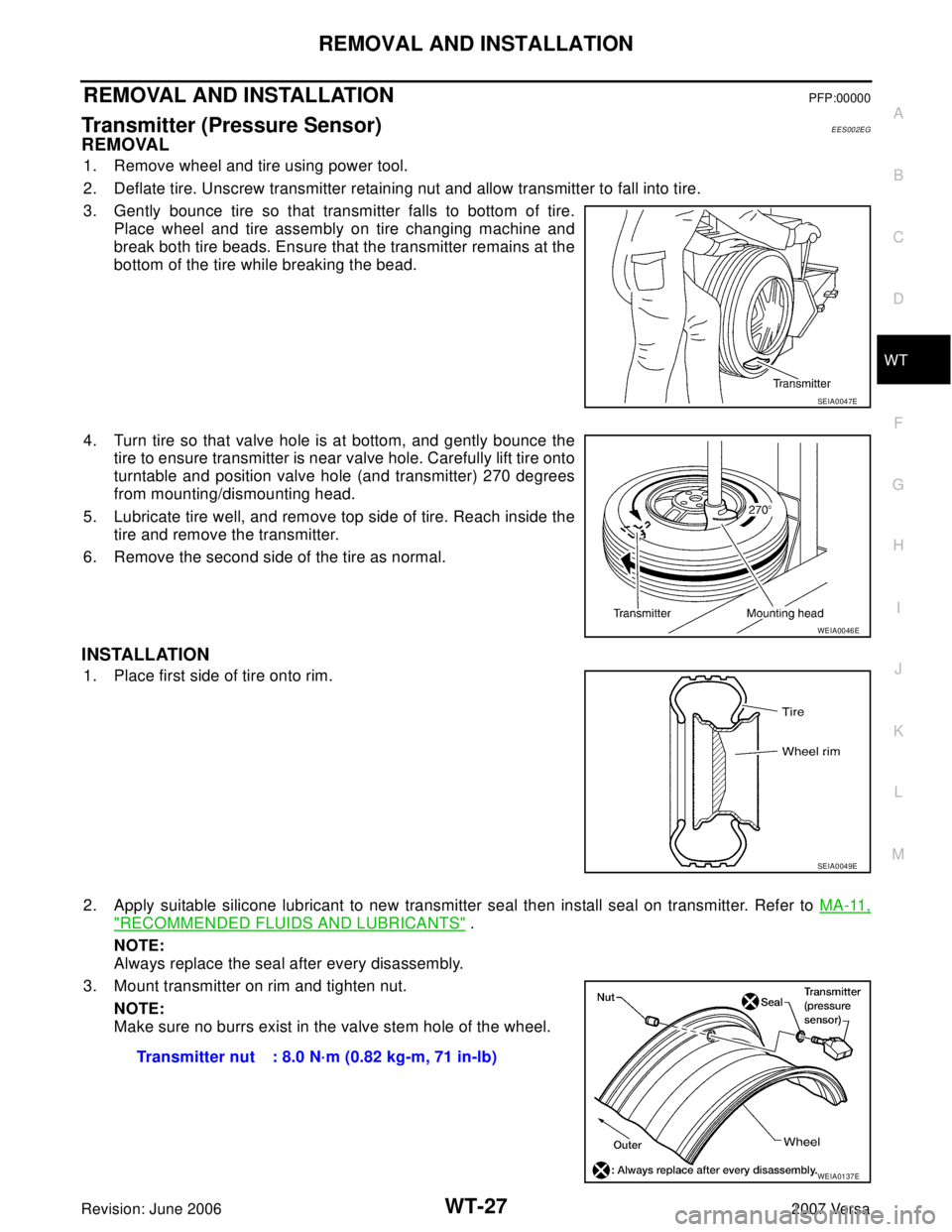
1. Remove wheel and tire using power tool.
2. Deflate tire. Unscrew transmitter retaining nut and allow transmitter to fall into tire.
3. Gently bounce tire so that transmitter falls to bottom of tire.
Place wheel and tire assembly on tire changing machine and
break both tire beads. Ensure that the transmitter remains at the
bottom of the tire while breaking the bead.
4. Turn tire so that valve hole is at bottom, and gently bounce the
tire to ensure transmitter is near valve hole. Carefully lift tire onto
turntable and position valve hole (and transmitter) 270 degrees
from mounting/dismounting head.
5. Lubricate tire well, and remove top side of tire. Reach inside the
tire and remove the transmitter.
6. Remove the second side of the tire as normal.
INSTALLATION
1. Place first side of tire onto rim.
2. Apply suitable silicone lubricant to new transmitter seal then install seal on transmitter. Refer to MA-11,
"RECOMMENDED FLUIDS AND LUBRICANTS" .
NOTE:
Always replace the seal after every disassembly.
3. Mount transmitter on rim and tighten nut.
NOTE:
Make sure no burrs exist in the valve stem hole of the wheel.
SEIA0047E
WEIA0046E
SEIA0049E
Transmitter nut : 8.0 N·m (0.82 kg-m, 71 in-lb)
WEIA0137E
Page 2877 of 2896

FRONT WIPER AND WASHER SYSTEM
WW-29
C
D
E
F
G
H
I
J
L
MA
B
WW
Revision: June 20062007 Versa
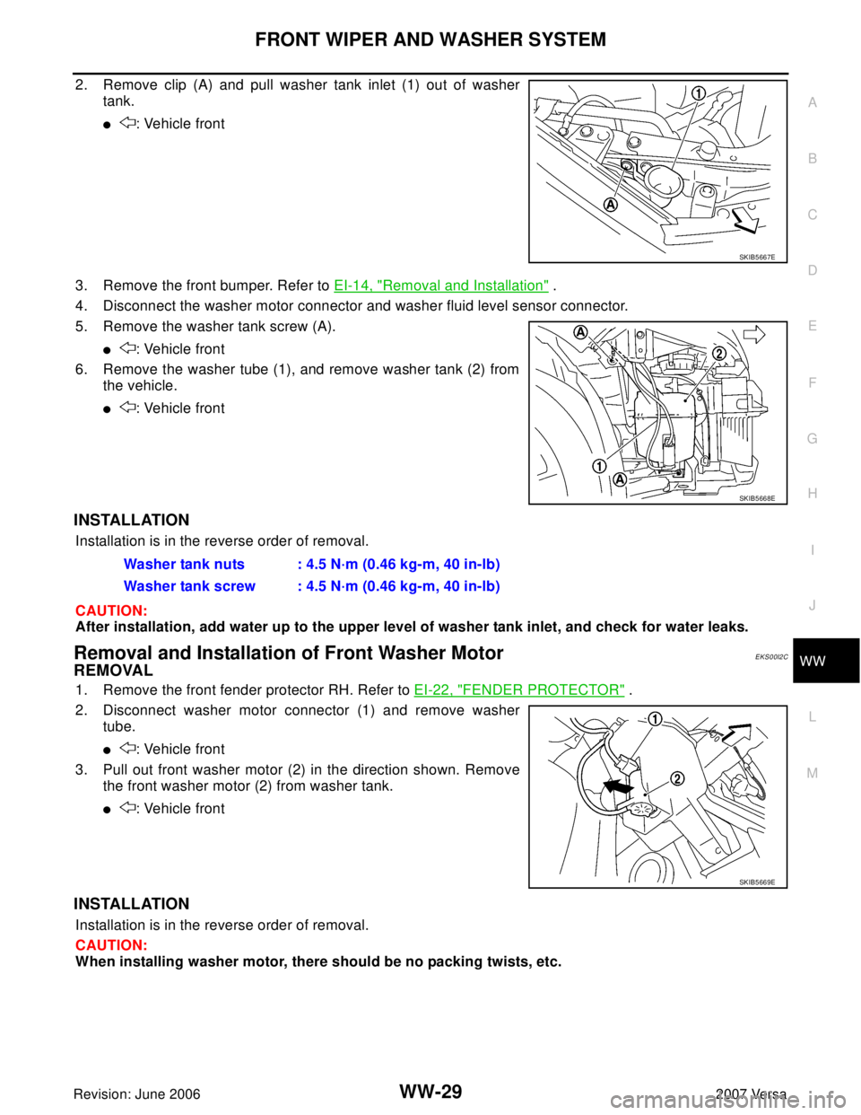
2. Remove clip (A) and pull washer tank inlet (1) out of washer
tank.
�: Vehicle front
3. Remove the front bumper. Refer to EI-14, "
Removal and Installation" .
4. Disconnect the washer motor connector and washer fluid level sensor connector.
5. Remove the washer tank screw (A).
�: Vehicle front
6. Remove the washer tube (1), and remove washer tank (2) from
the vehicle.
�: Vehicle front
INSTALLATION
Installation is in the reverse order of removal.
CAUTION:
After installation, add water up to the upper level of washer tank inlet, and check for water leaks.
Removal and Installation of Front Washer MotorEKS00I2C
REMOVAL
1. Remove the front fender protector RH. Refer to EI-22, "FENDER PROTECTOR" .
2. Disconnect washer motor connector (1) and remove washer
tube.
�: Vehicle front
3. Pull out front washer motor (2) in the direction shown. Remove
the front washer motor (2) from washer tank.
�: Vehicle front
INSTALLATION
Installation is in the reverse order of removal.
CAUTION:
When installing washer motor, there should be no packing twists, etc.
SKIB5667E
SKIB5668E
Washer tank nuts : 4.5 N·m (0.46 kg-m, 40 in-lb)
Washer tank screw : 4.5 N·m (0.46 kg-m, 40 in-lb)
SKIB5669E