Page 240 of 2896
TROUBLE DIAGNOSIS FOR SYMPTOMS
AT-227
D
E
F
G
H
I
J
K
L
MA
B
AT
Revision: June 20062007 Versa
11 . CHECK TCM
1. Check TCM input/output signals. Refer to AT- 7 8 , "
TCM Terminals and Reference Value" .
2. If NG, recheck TCM pin terminals for damage or loose connection with harness connector.
OK or NG
OK >> INSPECTION END
NG >> Repair or replace damaged parts.
TCM Self-diagnosis Does Not ActivateUCS005VF
SYMPTOM:
OD OFF indicator lamp does not come on in TCM self-diagnostic procedure even if the lamp circuit is
good.
DESCRIPTION
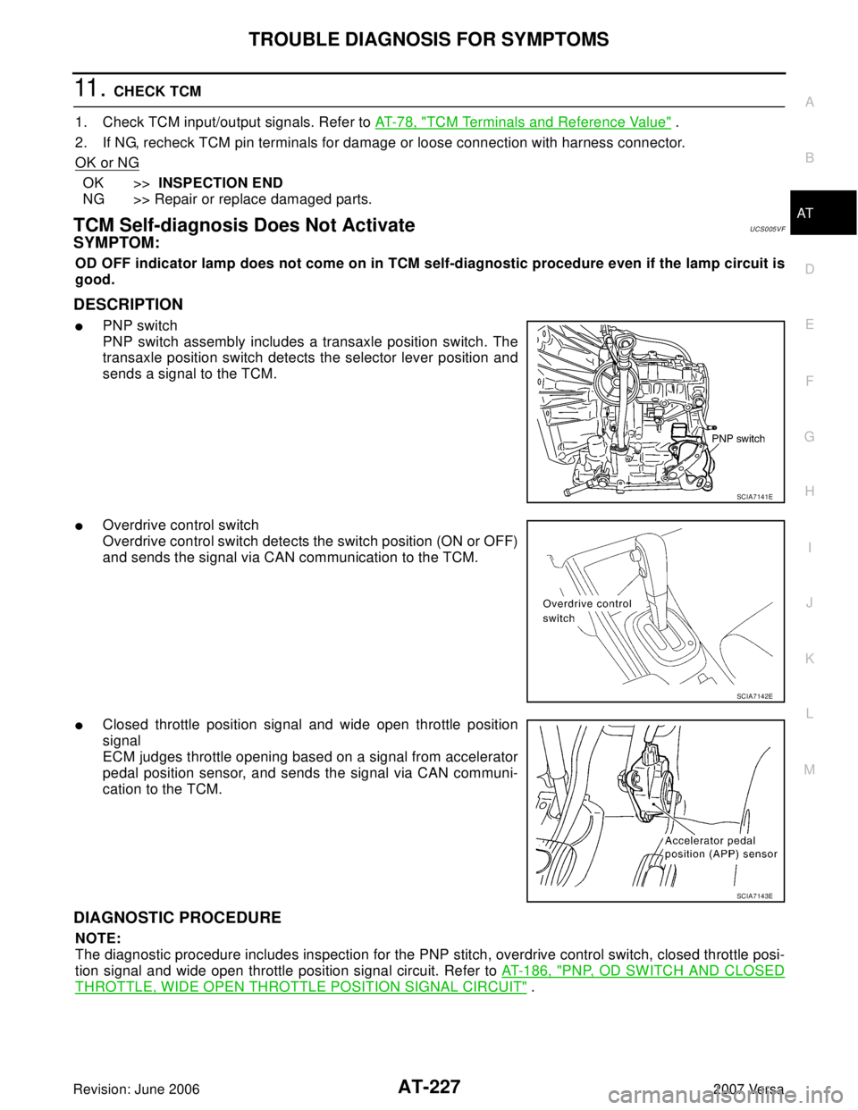
�PNP switch
PNP switch assembly includes a transaxle position switch. The
transaxle position switch detects the selector lever position and
sends a signal to the TCM.
�Overdrive control switch
Overdrive control switch detects the switch position (ON or OFF)
and sends the signal via CAN communication to the TCM.
�Closed throttle position signal and wide open throttle position
signal
ECM judges throttle opening based on a signal from accelerator
pedal position sensor, and sends the signal via CAN communi-
cation to the TCM.
DIAGNOSTIC PROCEDURE
NOTE:
The diagnostic procedure includes inspection for the PNP stitch, overdrive control switch, closed throttle posi-
tion signal and wide open throttle position signal circuit. Refer to AT-186, "
PNP, OD SWITCH AND CLOSED
THROTTLE, WIDE OPEN THROTTLE POSITION SIGNAL CIRCUIT" .
SCIA7141E
SCIA7142E
SCIA7143E
Page 260 of 2896
ON-VEHICLE SERVICE
AT-247
D
E
F
G
H
I
J
K
L
MA
B
AT
Revision: June 20062007 Versa
PARK/NEUTRAL POSITION (PNP) SWITCH ADJUSTMENT
1. Remove air duct (inlet). Refer to EM-16, "AIR CLEANER AND AIR DUCT" .
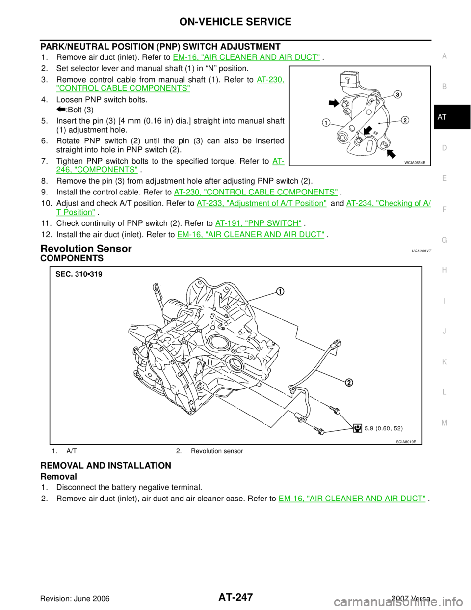
2. Set selector lever and manual shaft (1) in “N” position.
3. Remove control cable from manual shaft (1). Refer to AT-230,
"CONTROL CABLE COMPONENTS"
4. Loosen PNP switch bolts.
:Bolt (3)
5. Insert the pin (3) [4 mm (0.16 in) dia.] straight into manual shaft
(1) adjustment hole.
6. Rotate PNP switch (2) until the pin (3) can also be inserted
straight into hole in PNP switch (2).
7. Tighten PNP switch bolts to the specified torque. Refer to AT-
246, "COMPONENTS" .
8. Remove the pin (3) from adjustment hole after adjusting PNP switch (2).
9. Install the control cable. Refer to AT-230, "
CONTROL CABLE COMPONENTS" .
10. Adjust and check A/T position. Refer to AT-233, "
Adjustment of A/T Position" and AT- 2 3 4 , "Checking of A/
T Position" .
11. Check continuity of PNP switch (2). Refer to AT-191, "
PNP SWITCH" .
12. Install the air duct (inlet). Refer to EM-16, "
AIR CLEANER AND AIR DUCT" .
Revolution SensorUCS005VT
COMPONENTS
REMOVAL AND INSTALLATION
Removal
1. Disconnect the battery negative terminal.
2. Remove air duct (inlet), air duct and air cleaner case. Refer to EM-16, "
AIR CLEANER AND AIR DUCT" .
WCIA0654E
1. A/T 2. Revolution sensor
SCIA8019E
Page 261 of 2896
AT-248
ON-VEHICLE SERVICE
Revision: June 20062007 Versa
3. Disconnect revolution sensor harness connector.
4. Remove clip (A).
5. Remove revolution sensor (1) from A/T.
: Bolt (2)
6. Remove O-ring from revolution sensor (1)
Installation
Installation is in the reverse order of removal.
CAUTION:
�Do not reuse O-ring.
�Apply ATF to O-ring.
�Ensure revolution sensor harness is firmly secured with
bolt.
(1): Revolution sensor
: Bolt (1)
Turbine Revolution Sensor (Power Train Revolution Sensor) UCS005VU
COMPONENTS
REMOVAL AND INSTALLATION
Removal
1. Disconnect the battery negative terminal.
2. Remove air duct (inlet). Refer to EM-16, "
AIR CLEANER AND AIR DUCT" .
WCIA0655E
WCIA0656E
1. A/T 2. O-ring 3. Turbine revolution sensor (power
train revolution sensor)
SCIA8020E
Page 262 of 2896
ON-VEHICLE SERVICE
AT-249
D
E
F
G
H
I
J
K
L
MA
B
AT
Revision: June 20062007 Versa
3. Disconnect turbine revolution sensor (power train revolution
sensor) harness connector (1).
4. Remove turbine revolution sensor (power train revolution sen-
sor) bolt.
: Bolt (1)
5. Remove turbine revolution sensor (power train revolution sen-
sor) (2) from A/T.
6. Remove O-ring from turbine revolution sensor (power train revo-
lution sensor) (2).
Installation
Installation is in the reverse order of removal.
CAUTION:
�Do not reuse O-ring.
�Apply ATF to O-ring.
WCIA0658E
Page 267 of 2896
AT-254
TRANSAXLE ASSEMBLY
Revision: June 20062007 Versa
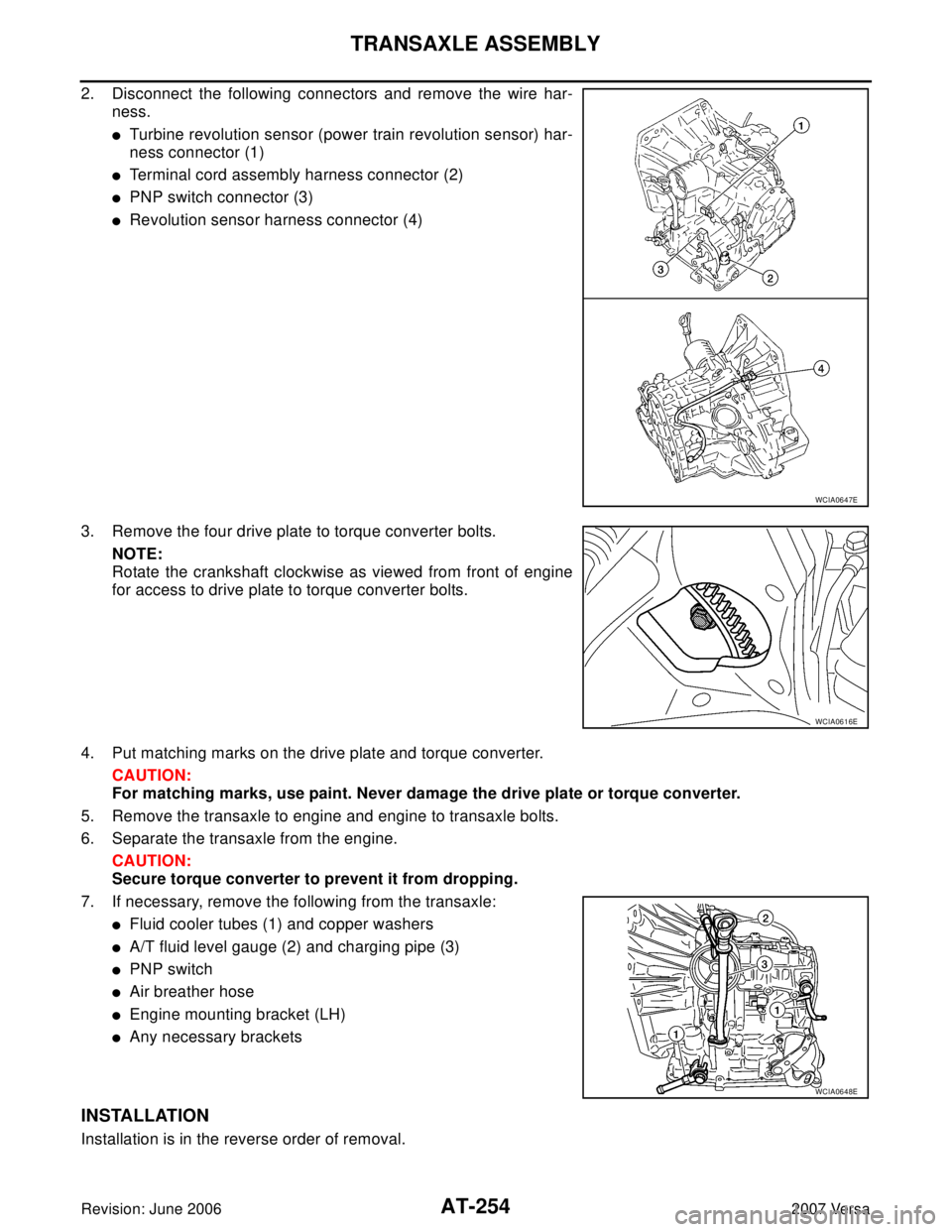
2. Disconnect the following connectors and remove the wire har-
ness.
�Turbine revolution sensor (power train revolution sensor) har-
ness connector (1)
�Terminal cord assembly harness connector (2)
�PNP switch connector (3)
�Revolution sensor harness connector (4)
3. Remove the four drive plate to torque converter bolts.
NOTE:
Rotate the crankshaft clockwise as viewed from front of engine
for access to drive plate to torque converter bolts.
4. Put matching marks on the drive plate and torque converter.
CAUTION:
For matching marks, use paint. Never damage the drive plate or torque converter.
5. Remove the transaxle to engine and engine to transaxle bolts.
6. Separate the transaxle from the engine.
CAUTION:
Secure torque converter to prevent it from dropping.
7. If necessary, remove the following from the transaxle:
�Fluid cooler tubes (1) and copper washers
�A/T fluid level gauge (2) and charging pipe (3)
�PNP switch
�Air breather hose
�Engine mounting bracket (LH)
�Any necessary brackets
INSTALLATION
Installation is in the reverse order of removal.
WCIA0647E
WCIA0616E
WCIA0648E
Page 277 of 2896
AT-264
OVERHAUL
Revision: June 20062007 Versa
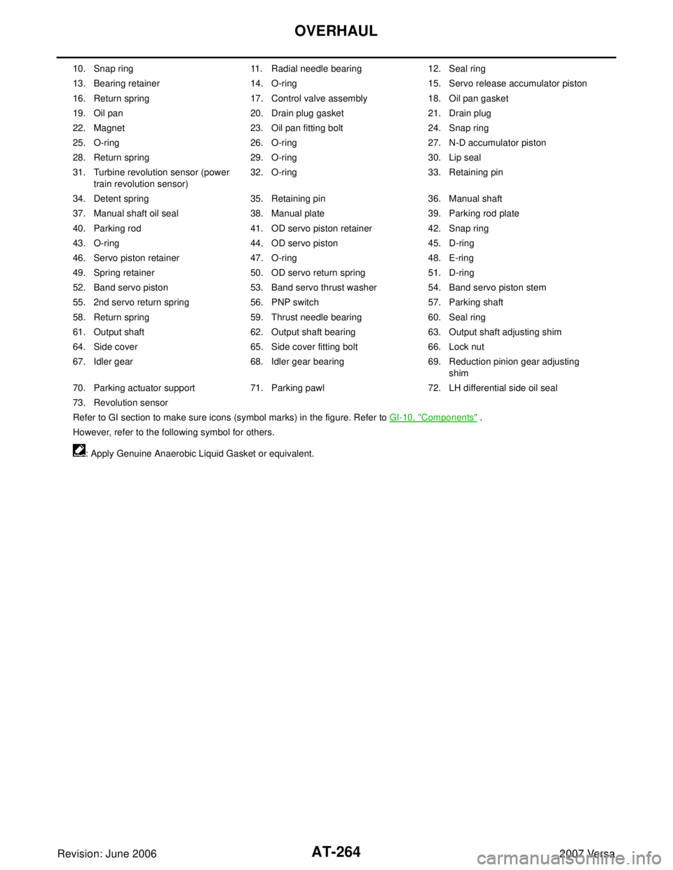
10. Snap ring 11. Radial needle bearing 12. Seal ring
13. Bearing retainer 14. O-ring 15. Servo release accumulator piston
16. Return spring 17. Control valve assembly 18. Oil pan gasket
19. Oil pan 20. Drain plug gasket 21. Drain plug
22. Magnet 23. Oil pan fitting bolt 24. Snap ring
25. O-ring 26. O-ring 27. N-D accumulator piston
28. Return spring 29. O-ring 30. Lip seal
31. Turbine revolution sensor (power
train revolution sensor)32. O-ring 33. Retaining pin
34. Detent spring 35. Retaining pin 36. Manual shaft
37. Manual shaft oil seal 38. Manual plate 39. Parking rod plate
40. Parking rod 41. OD servo piston retainer 42. Snap ring
43. O-ring 44. OD servo piston 45. D-ring
46. Servo piston retainer 47. O-ring 48. E-ring
49. Spring retainer 50. OD servo return spring 51. D-ring
52. Band servo piston 53. Band servo thrust washer 54. Band servo piston stem
55. 2nd servo return spring 56. PNP switch 57. Parking shaft
58. Return spring 59. Thrust needle bearing 60. Seal ring
61. Output shaft 62. Output shaft bearing 63. Output shaft adjusting shim
64. Side cover 65. Side cover fitting bolt 66. Lock nut
67. Idler gear 68. Idler gear bearing 69. Reduction pinion gear adjusting
shim
70. Parking actuator support 71. Parking pawl 72. LH differential side oil seal
73. Revolution sensor
Refer to GI section to make sure icons (symbol marks) in the figure. Refer to GI-10, "
Components" .
However, refer to the following symbol for others.
: Apply Genuine Anaerobic Liquid Gasket or equivalent.
Page 282 of 2896
DISASSEMBLY
AT-269
D
E
F
G
H
I
J
K
L
MA
B
AT
Revision: June 20062007 Versa
5. Remove turbine revolution sensor (power train revolution sen-
sor) (1) from transaxle case (2).
: Bolt (1)
6. Remove O-ring (3) from turbine revolution sensor (power train
revolution sensor) (1).
7. Remove revolution sensor (1) from transaxle case (2).
: Bolt (2)
8. Remove plug or speedometer pinion according to the following procedures.
a. With ABS
i. Remove plug (1) from converter housing (2).
: Bolt (1)
ii. Remove O-ring (3) from plug (1).
b. Without ABS
i. Remove speedometer pinion (1) from converter housing (2).
: Bolt (1)
ii. Remove O-ring (3) from speedometer pinion (1).
SCIA7004J
SCIA7170J
SCIA7747E
SCIA7462E
Page 310 of 2896
REPAIR FOR COMPONENT PARTS
AT-297
D
E
F
G
H
I
J
K
L
MA
B
AT
Revision: June 20062007 Versa
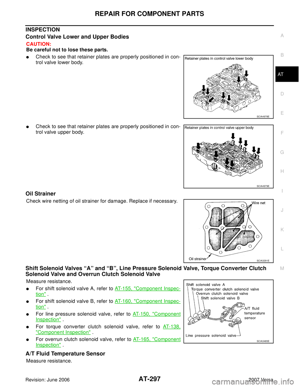
INSPECTION
Control Valve Lower and Upper Bodies
CAUTION:
Be careful not to lose these parts.
�Check to see that retainer plates are properly positioned in con-
trol valve lower body.
�Check to see that retainer plates are properly positioned in con-
trol valve upper body.
Oil Strainer
Check wire netting of oil strainer for damage. Replace if necessary.
Shift Solenoid Valves “A” and “B”, Line Pressure Solenoid Valve, Torque Converter Clutch
Solenoid Valve and Overrun Clutch Solenoid Valve
Measure resistance.
�For shift solenoid valve A, refer to AT-155, "Component Inspec-
tion" .
�For shift solenoid valve B, refer to AT-160, "Component Inspec-
tion" .
�For line pressure solenoid valve, refer to AT-150, "Component
Inspection" .
�For torque converter clutch solenoid valve, refer to AT-138,
"Component Inspection" .
�For overrun clutch solenoid valve, refer to AT-165, "Component
Inspection" .
A/T Fluid Temperature Sensor
Measure resistance.
SCIA4978E
SCIA4979E
SCIA3291E
SCIA3485E