Page 1 of 2896

-1
QUICK REFERENCE INDEX
AGENERAL INFORMATIONGIGeneral Information
BENGINEEMEngine Mechanical
LUEngine Lubrication System
COEngine Cooling System
ECEngine Control System
FLFuel System
EXExhaust System
ACCAccelerator Control System
CTRANSMISSION/
TRANSAXLECLClutch System
MTManual Transaxle
ATAutomatic Transaxle
CVTCVT
DDRIVELINE/AXLEFAXFront Axle
RAXRear Axle
ESUSPENSIONFSUFront Suspension
RSURear Suspension
WTRoad Wheels & Tires
FBRAKESBRBrake System
PBParking Brake System
BRCBrake Control System
GSTEERINGPSPower Steering System
STCSteering Control System
HRESTRAINTSSBSeat Belts
SRSSupplemental Restraint System (SRS)
IBODYBLBody, Lock & Security System
GWGlasses, Window System & Mirrors
RFRoof
EIExterior & Interior
IPInstrument Panel
SESeat
JAIR CONDITIONERMTCManual Air Conditioner
KELECTRICALSCStarting & Charging System
LTLighting System
DIDriver Information System
WWWiper, Washer & Horn
BCSBody Control System
LANLAN System
AVAudio Visual, Navigation & Telephone System
ACSAuto Cruise Control System
PGPower Supply, Ground & Circuit Elements
LMAINTENANCEMAMaintenance
MINDEXIDXAlphabetical Index
Edition: June 2006
Revision: June 2006
Publication No. SM7E-1C11U0
B
D
© 2006 NISSAN NORTH AMERICA, INC.
All rights reserved. No part of this Service Manual may be reproduced or stored in a retrieval system, or transmitted in any
form, or by any means, electronic, mechanical, photo-copying, recording or otherwise, without the prior written permission
of Nissan North America Inc.
A
C
E
F
G
H
I
J
K
L
M
Page 722 of 2896
BODY REPAIR
BL-233
C
D
E
F
G
H
J
K
L
MA
B
BL
Revision: June 20062007 Versa
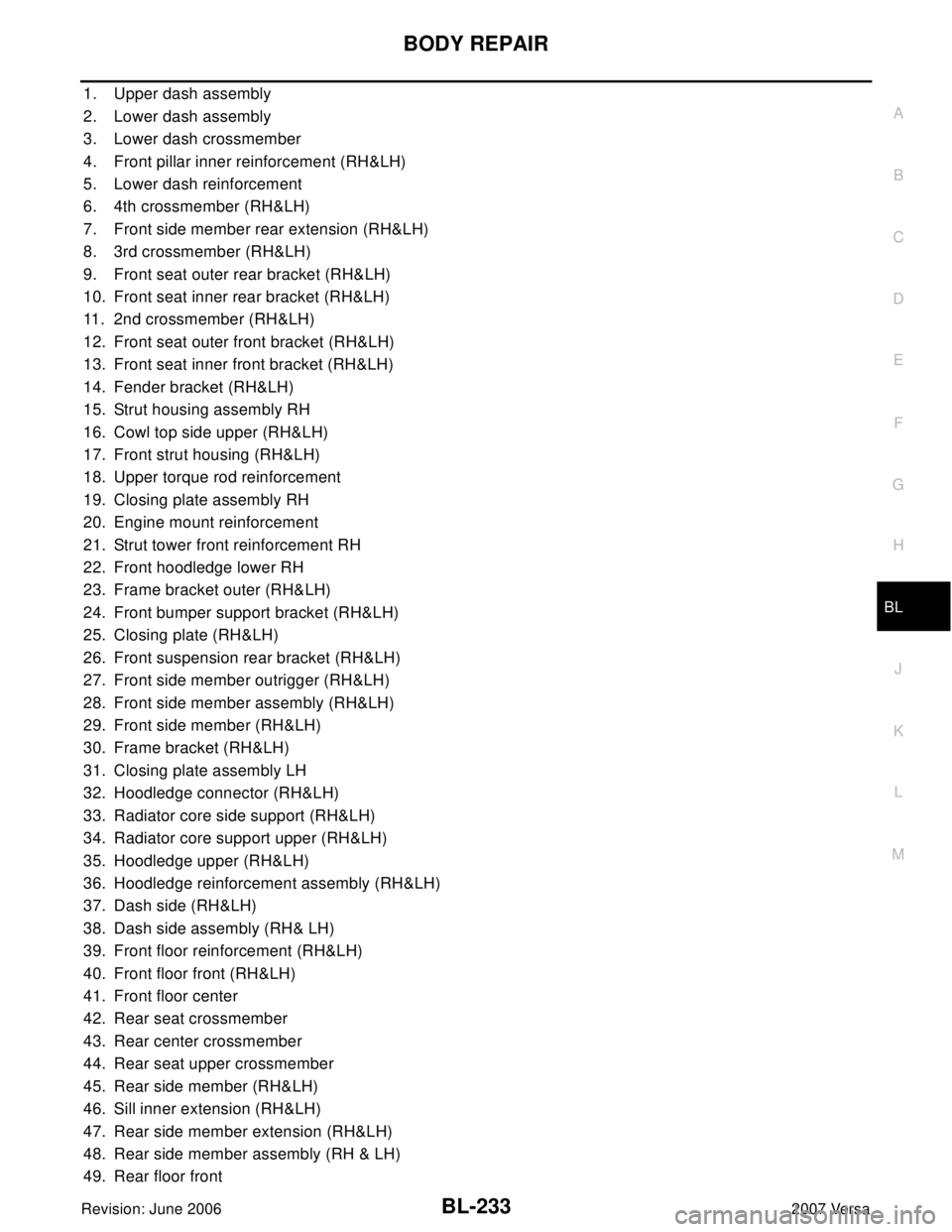
1. Upper dash assembly
2. Lower dash assembly
3. Lower dash crossmember
4. Front pillar inner reinforcement (RH&LH)
5. Lower dash reinforcement
6. 4th crossmember (RH&LH)
7. Front side member rear extension (RH&LH)
8. 3rd crossmember (RH&LH)
9. Front seat outer rear bracket (RH&LH)
10. Front seat inner rear bracket (RH&LH)
11. 2nd crossmember (RH&LH)
12. Front seat outer front bracket (RH&LH)
13. Front seat inner front bracket (RH&LH)
14. Fender bracket (RH&LH)
15. Strut housing assembly RH
16. Cowl top side upper (RH&LH)
17. Front strut housing (RH&LH)
18. Upper torque rod reinforcement
19. Closing plate assembly RH
20. Engine mount reinforcement
21. Strut tower front reinforcement RH
22. Front hoodledge lower RH
23. Frame bracket outer (RH&LH)
24. Front bumper support bracket (RH&LH)
25. Closing plate (RH&LH)
26. Front suspension rear bracket (RH&LH)
27. Front side member outrigger (RH&LH)
28. Front side member assembly (RH&LH)
29. Front side member (RH&LH)
30. Frame bracket (RH&LH)
31. Closing plate assembly LH
32. Hoodledge connector (RH&LH)
33. Radiator core side support (RH&LH)
34. Radiator core support upper (RH&LH)
35. Hoodledge upper (RH&LH)
36. Hoodledge reinforcement assembly (RH&LH)
37. Dash side (RH&LH)
38. Dash side assembly (RH& LH)
39. Front floor reinforcement (RH&LH)
40. Front floor front (RH&LH)
41. Front floor center
42. Rear seat crossmember
43. Rear center crossmember
44. Rear seat upper crossmember
45. Rear side member (RH&LH)
46. Sill inner extension (RH&LH)
47. Rear side member extension (RH&LH)
48. Rear side member assembly (RH & LH)
49. Rear floor front
Page 788 of 2896
NOISE, VIBRATION AND HARSHNESS (NVH) TROUBLESHOOTING
BR-5
C
D
E
G
H
I
J
K
L
MA
B
BR
Revision: June 20062007 Versa
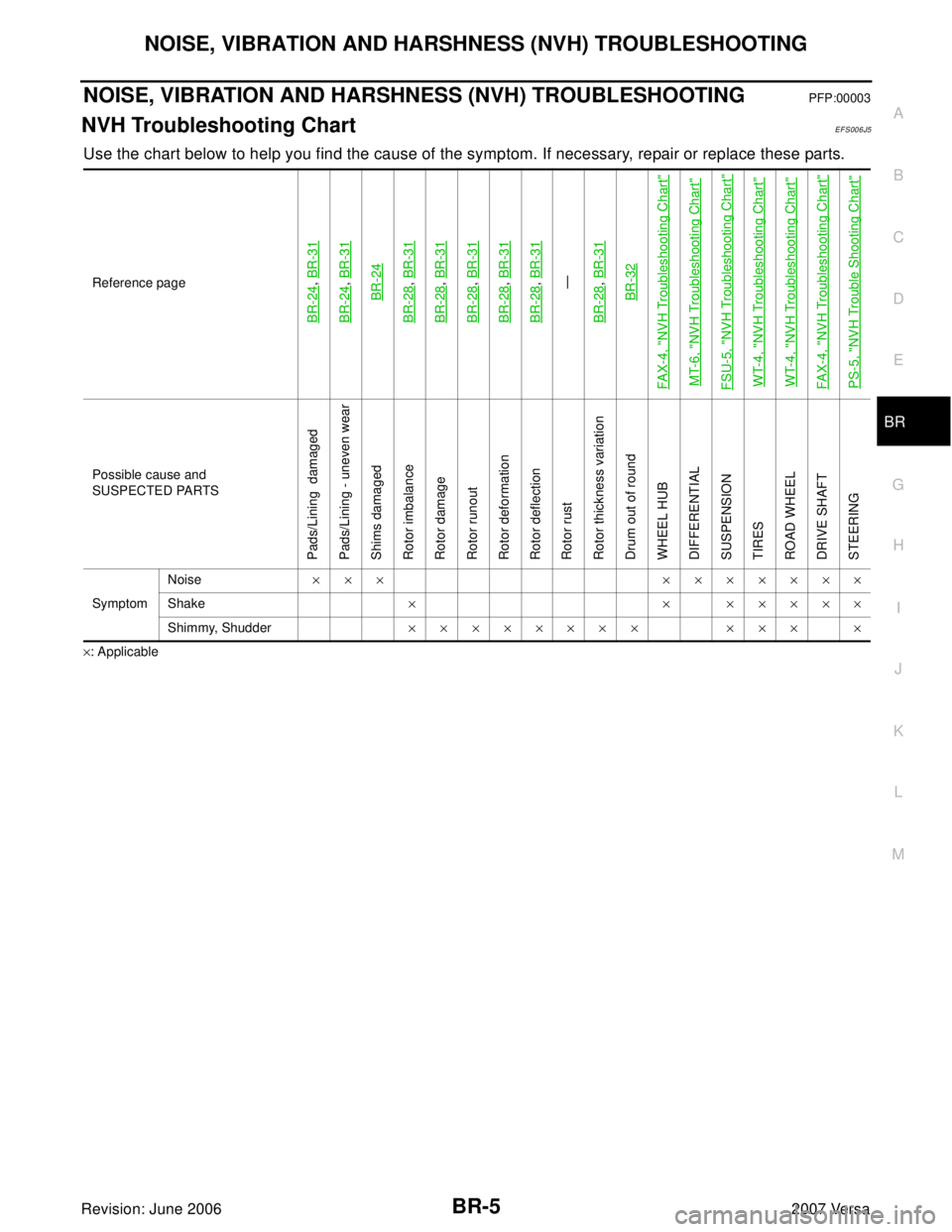
NOISE, VIBRATION AND HARSHNESS (NVH) TROUBLESHOOTINGPFP:00003
NVH Troubleshooting ChartEFS006J5
Use the chart below to help you find the cause of the symptom. If necessary, repair or replace these parts.
×: ApplicableReference page
BR-24
, BR-31
BR-24
, BR-31BR-24
BR-28
, BR-31
BR-28
, BR-31
BR-28
, BR-31
BR-28
, BR-31
BR-28
, BR-31—
BR-28, BR-31BR-32
FA X-4, "
NVH Troubleshooting Chart
"
MT-6, "
NVH Troubleshooting Chart
"
FSU-5, "
NVH Troubleshooting Chart
"
WT-4, "
NVH Troubleshooting Chart
"
WT-4, "
NVH Troubleshooting Chart
"
FA X-4, "
NVH Troubleshooting Chart
"
PS-5, "
NVH Trouble Shooting Chart
"
Possible cause and
SUSPECTED PARTS
Pads/Lining damaged
Pads/Lining - uneven wear
Shims damaged
Rotor imbalance
Rotor damage
Rotor runout
Rotor deformation
Rotor deflection
Rotor rust
Rotor thickness variation
Drum out of round
WHEEL HUB
DIFFERENTIAL
SUSPENSION
TIRES
ROAD WHEEL
DRIVE SHAFT
STEERING
SymptomNoise××× ×××××××
Shake× × ×××××
Shimmy, Shudder×××××××× ××× ×
Page 853 of 2896
BRC-34
[ABS]
WHEEL SENSORS
Revision: June 20062007 Versa
�When installing rear wheel sensor, press rubber grommets of suspension arm bracket and harness of side
member all the way in until they get locked, and be careful not to apply a twist to harness. Harness should
not be twisted after installation. (Aim the paint mark upward of vehicle.)
Page 1935 of 2896
FAX-4
NOISE, VIBRATION AND HARSHNESS (NVH) TROUBLESHOOTING
Revision: June 20062007 Versa
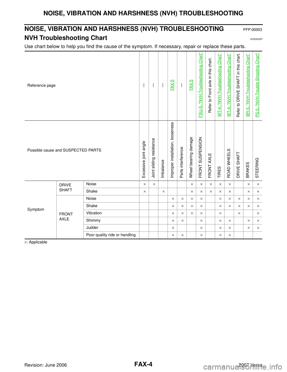
NOISE, VIBRATION AND HARSHNESS (NVH) TROUBLESHOOTINGPFP:00003
NVH Troubleshooting ChartEDS003QP
Use chart below to help you find the cause of the symptom. If necessary, repair or replace these parts.
×: ApplicableReference page
—
—
—
FA X - 5—
FA X - 5
FSU-5, "
NVH Troubleshooting Chart
"
Refer to Front axle in this chart.
WT-4, "
NVH Troubleshooting Chart
"
WT-4, "
NVH Troubleshooting Chart
"
Refer to DRIVE SHAFT in this chart.
BR-5, "
NVH Troubleshooting Chart
"
PS-5, "
NVH Trouble Shooting Chart
"
Possible cause and SUSPECTED PARTS
Excessive joint angle
Joint sliding resistance
Imbalance
Improper installation, looseness
Parts interference
Wheel bearing damage
FRONT SUSPENSION
FRONT AXLE
TIRES
ROAD WHEELS
DRIVE SHAFT
BRAKES
STEERING
SymptomDRIVE
SHAFTNoise×× ××××× ××
Shake× × ××××× ××
FRONT
AXLENoise×××× ×××××
Shake×××× ×××××
Vibration×××××××
Shimmy×××××××
Judder× × ×× ××
Poor quality ride or handling×××××
Page 1936 of 2896
FRONT WHEEL HUB AND KNUCKLE
FAX-5
C
E
F
G
H
I
J
K
L
MA
B
FA X
Revision: June 20062007 Versa
FRONT WHEEL HUB AND KNUCKLEPFP:40202
On-Vehicle Inspection and ServiceEDS003TJ
�Check the axle and suspension parts for excessive play, wear, or damage.
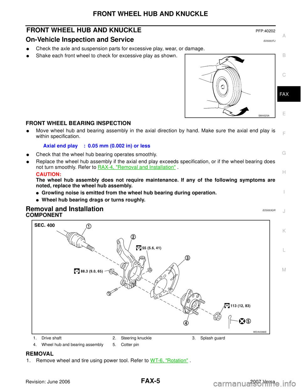
�Shake each front wheel to check for excessive play as shown.
FRONT WHEEL BEARING INSPECTION
�Move wheel hub and bearing assembly in the axial direction by hand. Make sure the axial end play is
within specification.
�Check that the wheel hub bearing operates smoothly.
�Replace the wheel hub assembly if the axial end play exceeds specification, or if the wheel bearing does
not turn smoothly. Refer to RAX-4, "
Removal and Installation" .
CAUTION:
The wheel hub assembly does not require maintenance. If any of the following symptoms are
noted, replace the wheel hub assembly.
�Growling noise is emitted from the wheel hub bearing during operation.
�Wheel hub bearing drags or turns roughly.
Removal and InstallationEDS003QR
COMPONENT
REMOVAL
1. Remove wheel and tire using power tool. Refer to WT-6, "Rotation" .
SM A52 5A
Axial end play : 0.05 mm (0.002 in) or less
1. Drive shaft 2. Steering knuckle 3. Splash guard
4. Wheel hub and bearing assembly 5. Cotter pin
WDIA0366E
Page 1968 of 2896
FUEL TANK
FL-11
C
D
E
F
G
H
I
J
K
L
MA
FL
Revision: June 20062007 Versa
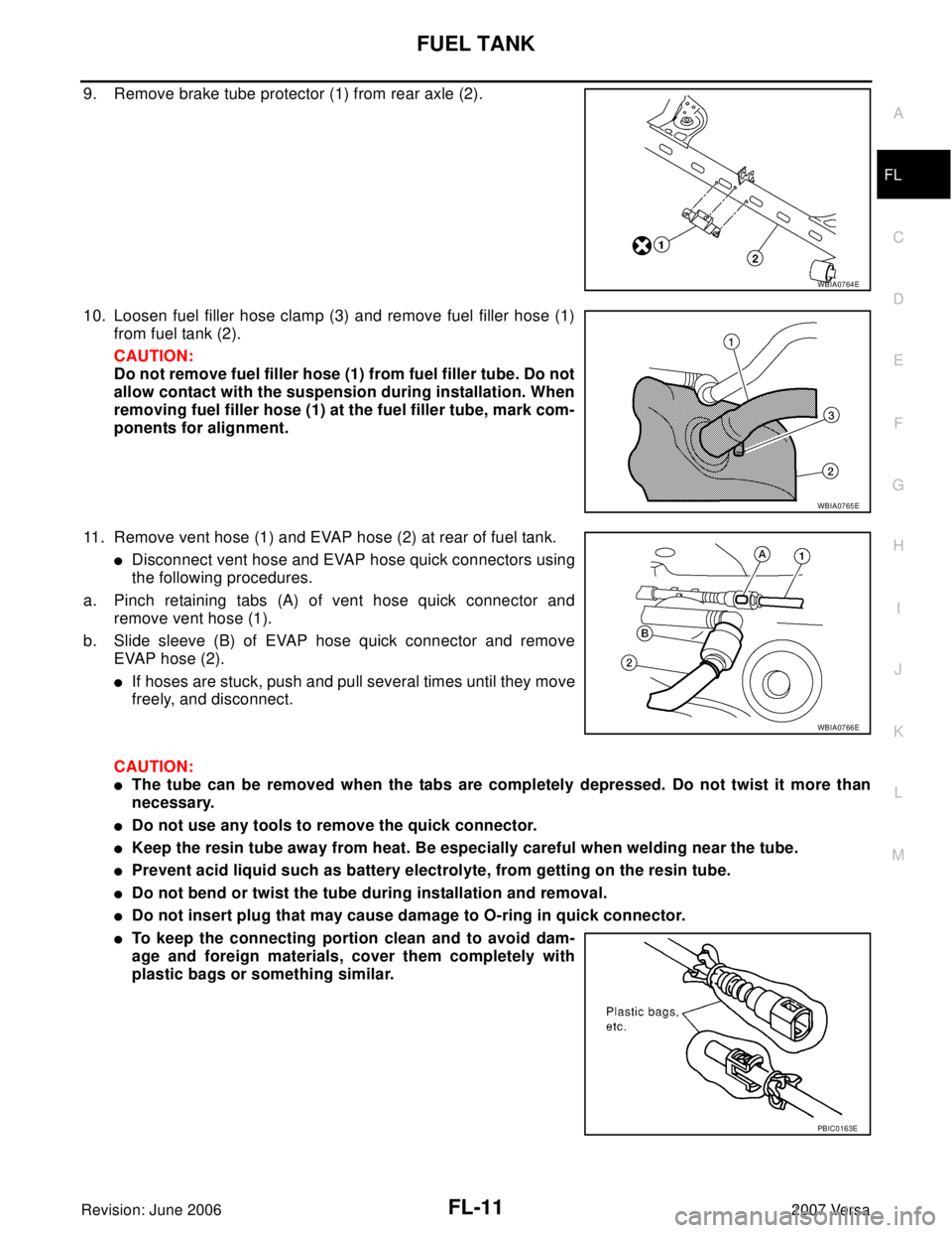
9. Remove brake tube protector (1) from rear axle (2).
10. Loosen fuel filler hose clamp (3) and remove fuel filler hose (1)
from fuel tank (2).
CAUTION:
Do not remove fuel filler hose (1) from fuel filler tube. Do not
allow contact with the suspension during installation. When
removing fuel filler hose (1) at the fuel filler tube, mark com-
ponents for alignment.
11. Remove vent hose (1) and EVAP hose (2) at rear of fuel tank.
�Disconnect vent hose and EVAP hose quick connectors using
the following procedures.
a. Pinch retaining tabs (A) of vent hose quick connector and
remove vent hose (1).
b. Slide sleeve (B) of EVAP hose quick connector and remove
EVAP hose (2).
�If hoses are stuck, push and pull several times until they move
freely, and disconnect.
CAUTION:
�The tube can be removed when the tabs are completely depressed. Do not twist it more than
necessary.
�Do not use any tools to remove the quick connector.
�Keep the resin tube away from heat. Be especially careful when welding near the tube.
�Prevent acid liquid such as battery electrolyte, from getting on the resin tube.
�Do not bend or twist the tube during installation and removal.
�Do not insert plug that may cause damage to O-ring in quick connector.
�To keep the connecting portion clean and to avoid dam-
age and foreign materials, cover them completely with
plastic bags or something similar.
WBIA0764E
WBIA0765E
WBIA0766E
PBIC0163E
Page 2013 of 2896
GI-42
LIFTING POINT
Revision: June 20062007 Versa
LIFTING POINTPFP:00000
Special Service Tools EAS001ZY
CAUTION:
�Every time the vehicle is lifted up, maintain the complete vehicle curb condition.
�Since the vehicle's center of gravity changes when removing main parts on the front side (engine,
transmission, suspension etc.), support a jack up point on the rear side garage jack with a mission
jack or equivalent.
�Since the vehicle's center of gravity changes when removing main parts on the rear side (rear axle,
suspension, etc.), support a jack up point on the front side garage jack with a mission jack or
equivalent.
�Be careful not to smash or do not do anything that would affect piping parts.
Garage Jack and Safety Stand and 2-Pole LiftEAS001ZZ
WAR NIN G:
�Park the vehicle on a level surface when using the jack. Make sure to avoid damaging pipes,
tubes, etc. under the vehicle.
�Never get under the vehicle while it is supported only by the jack. Always use safety stands when
you have to get under the vehicle.
�Place wheel chocks at both front and back of the wheels on the ground.
�When lifting the vehicle, open the lift arms as wide as possible and ensure that the front and rear
of the vehicle are well balanced.
�When setting the lift arm, do not allow the arm to contact the brake tubes, brake cable, fuel lines
and sill spoiler.
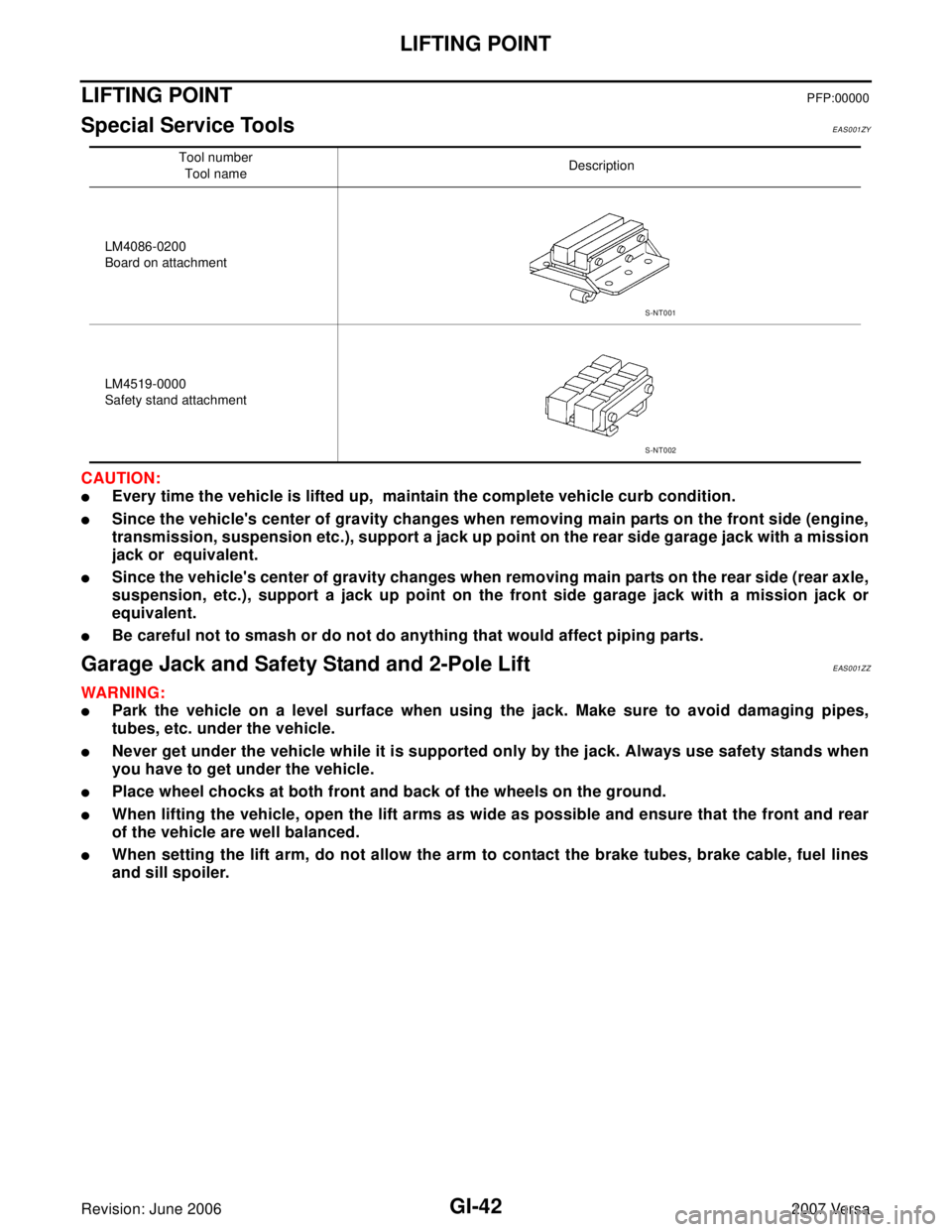
Tool number
Tool nameDescription
LM4086-0200
Board on attachment
LM4519-0000
Safety stand attachment
S-NT001
S-NT002