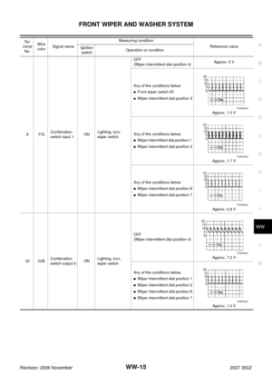
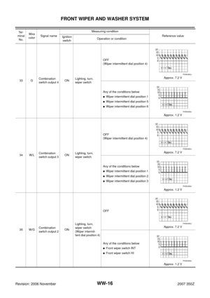
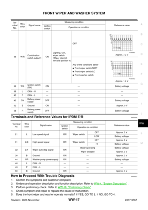
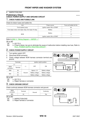
Page 49 of 54
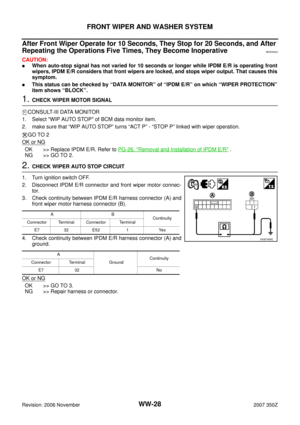
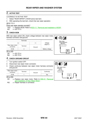
REAR WIPER AND WASHER SYSTEM
WW-49
C
D
E
F
G
H
I
J
L
MA
B
WW
Revision: 2006 November2007 350Z
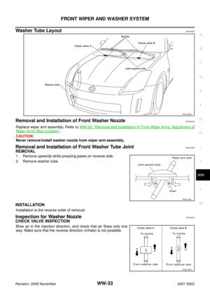
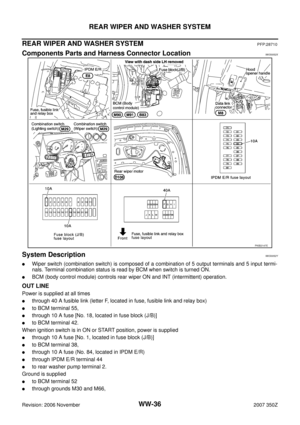
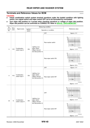
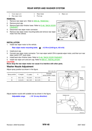
Washer Tube LayoutNKS0053D
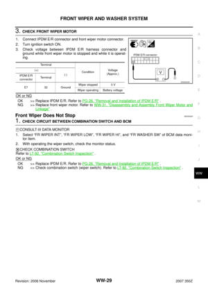
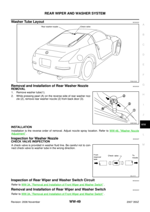
Removal and Installation of Rear Washer NozzleNKS0053E
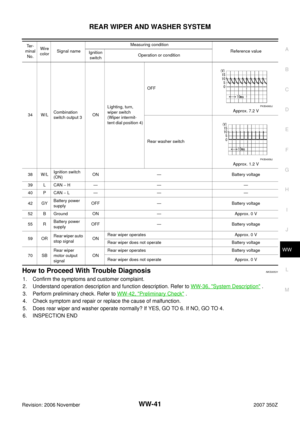
REMOVAL
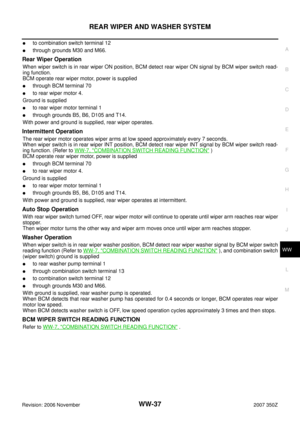
1. Remove washer tube(1).
2. While pressing pawl (A) on the reverse side of rear washer noz-
zle (2), remove rear washer nozzle (2) from back door (3).
INSTALLATION
Installation is the reverse order of removal. Adjust nozzle spray location. Refer to WW-48, "Washer Nozzle
Adjustment" .
Inspection for Washer NozzleNKS0053F
CHECK VALVE INSPECTION
A check valve is provided in washer fluid line. Be careful not to con-
nect check valve to washer tube in the wrong direction.
Inspection of Rear Wiper and Washer Switch CircuitNKS0053G
Refer to WW-34, "Removal and Installation of Front Wiper and Washer Switch" .
Removal and Installation of Rear Wiper and Washer SwitchNKS0053H
Refer to WW-34, "Removal and Installation of Front Wiper and Washer Switch" .
PKIA1912E
SKIB7454E
SEL411H
Page 50 of 54
WW-50
REAR WIPER AND WASHER SYSTEM
Revision: 2006 November2007 350Z
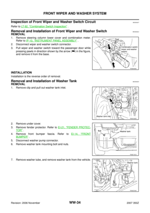
Removal and Installation of Washer TankNKS0053I
Refer to WW-34, "Removal and Installation of Washer Tank" .
Removal and Installation of Washer PumpNKS0053J
Refer to WW-35, "Removal and Installation of Washer Pump" .
Page 51 of 54
POWER SOCKET
WW-51
C
D
E
F
G
H
I
J
L
MA
B
WW
Revision: 2006 November2007 350Z
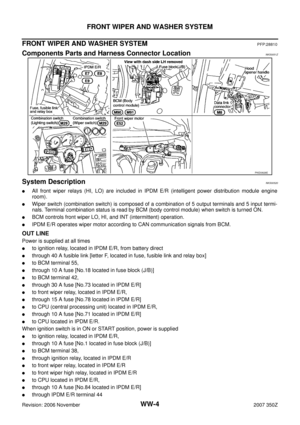
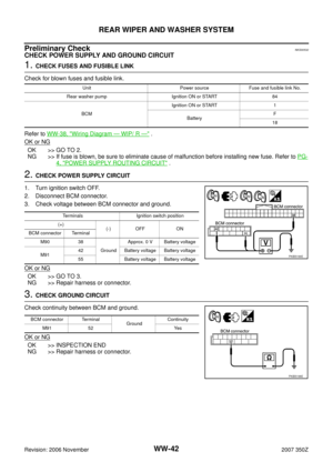
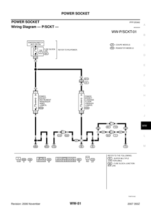
POWER SOCKETPFP:253A2
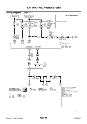
Wiring Diagram — P/SCKT —NKS0053K
TKWT5740E
Page 52 of 54
WW-52
POWER SOCKET
Revision: 2006 November2007 350Z
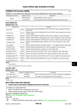
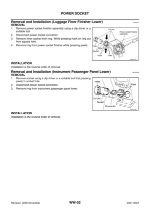
Removal and Installation (Luggage Floor Finisher Lower)NKS0053L
REMOVAL
1. Remove power socket finisher assembly using a clip driver or a
suitable tool.
2. Disconnect power socket connector.
3. Remove inner socket from ring. While pressing hook on ring out
from square hole.
4. Remove ring from power socket finisher while pressing pawls.
INSTALLATION
Installation is the reverse order of removal.
Removal and Installation (Instrument Passenger Panel Lower)NKS0053M
REMOVAL
1. Remove socket using a clip driver or a suitable tool that pressing
pawls in socket hole.
2. Disconnect power socket connector.
3. Remove ring from instrument passenger panel lower.
INSTALLATION
Installation is the reverse order of removal.
PKIA1915E
PKIB1789E
Page 53 of 54
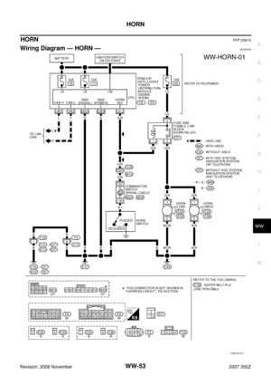
HORN
WW-53
C
D
E
F
G
H
I
J
L
MA
B
WW
Revision: 2006 November2007 350Z
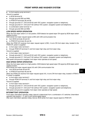
HORNPFP:25610
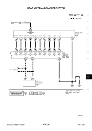
Wiring Diagram — HORN —NKS0053N
TKWT5741E
Page 54 of 54
WW-54
HORN
Revision: 2006 November2007 350Z
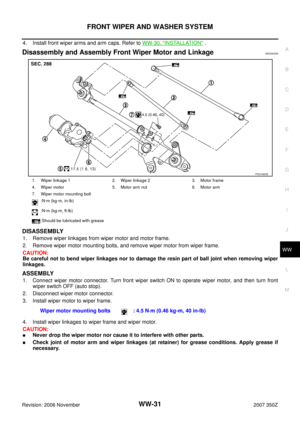
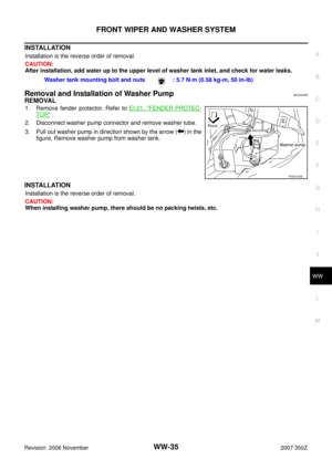
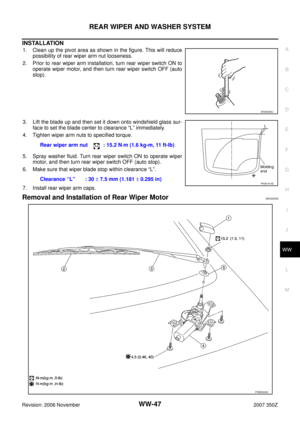
Removal and InstallationNKS0053O
REMOVAL
1. Disconnect all horn connectors.
2. Remove horn mounting bolt and remove horn from vehicle.
INSTALLATION
Tighten horn bolt to specified torque.
PKIA1917E
Horn mounting bolt : 5.7 N·m (0.58 kg-m, 50 in-lb)


NKS0053L
REMOVAL
1. Remove power socket finisher assembly using a clip driver or a
suitable t")

