Page 25 of 54

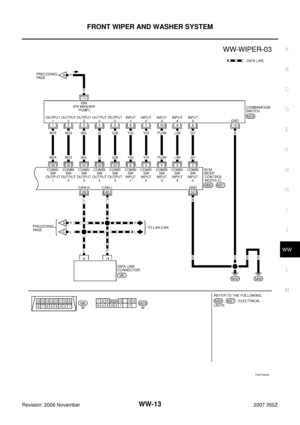
FRONT WIPER AND WASHER SYSTEM
WW-25
C
D
E
F
G
H
I
J
L
MA
B
WW
Revision: 2006 November2007 350Z
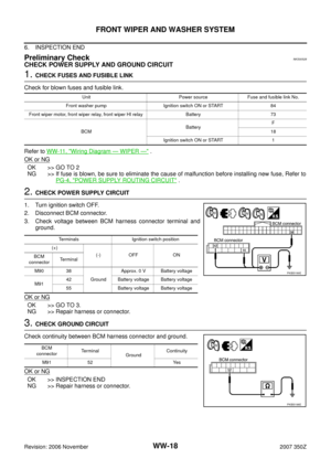
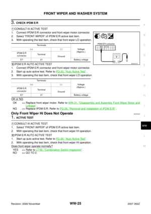
3. CHECK IPDM E/R
CONSULT-III ACTIVE TEST
1. Connect IPDM E/R connector and front wiper motor connector.
2. Select "FRONT WIPER" of IPDM E/R active test item.
3. With operating the test item, check that front wiper LO operation.
IPDM E/R AUTO ACTIVE TEST
1. Connect IPDM E/R connector and front wiper motor connector.
2. Start up auto active test. Refer to PG-20, "
Auto Active Test" .
3. With operating the test item, check that front wiper LO operation.
OK or NG
OK >> Replace front wiper motor. Refer to WW-31, "Disassembly and Assembly Front Wiper Motor and
Linkage" .
NG >> Replace IPDM E/R. Refer to PG-26, "
Removal and Installation of IPDM E/R" .
Only Front Wiper Hi Does Not OperateNKS0052E
1. ACTIVE TEST
CONSULT-III ACTIVE TEST
1. Select "FRONT WIPER" of IPDM E/R active test item.
2. With operating the test item, check that front wiper HI operation.
IPDM E/R AUTO ACTIVE TEST
1. Start up auto active test. Refer to PG-20, "
Auto Active Test"
2. With operating the test item, check that front wiper HI operation.
Does front wiper operate normally?
YES >> Refer to LT- 9 2 , "Combination Switch Inspection" .
NO >> GO TO 2.
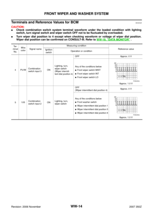
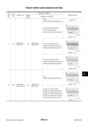
Terminals
Voltage
(Approx.) (+) (-)
IPDM E/R
connectorTerminal
Ground
E7 21 Battery voltage
Terminals
Voltage
(Approx.) (+) (-)
IPDM E/R
connectorTerminal
Ground
E7 21 Battery voltage
SKIA9167E
Page 26 of 54

WW-26
FRONT WIPER AND WASHER SYSTEM
Revision: 2006 November2007 350Z
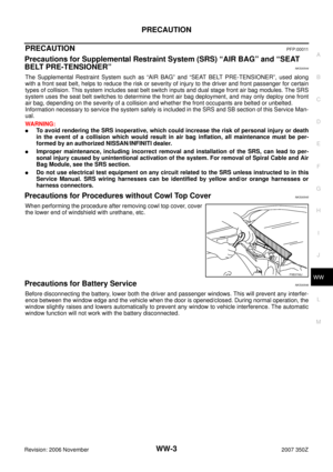
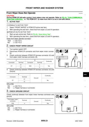
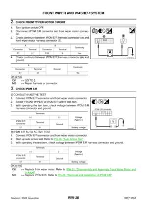
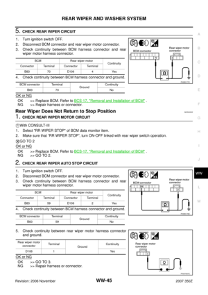
2. CHECK FRONT WIPER MOTOR CIRCUIT
1. Turn ignition switch OFF.
2. Disconnect IPDM E/R connector and front wiper motor connec-
tor.
3. Check continuity between IPDM E/R harness connector (A) and
front wiper motor harness connector (B).
4. Check continuity between IPDM E/R harness connector (A) and
ground.
OK or NG
OK >> GO TO 3.
NG >> Repair harness or connector.
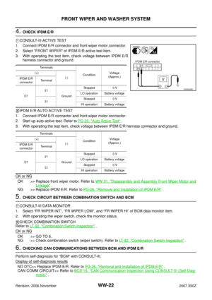
3. CHECK IPDM E/R
CONSULT-III ACTIVE TEST
1. Connect IPDM E/R connector and front wiper motor connector.
2. Select "FRONT WIPER" of IPDM E/R active test item.
3. With operating the test item, check voltage between IPDM E/R
harness connector and ground.
IPDM E/R AUTO ACTIVE TEST
1. Connect IPDM E/R connector and front wiper motor connector.
2. Start up auto active test. Refer to PG-20, "
Auto Active Test" .
3. With operating the test item, check voltage between IPDM E/R harness connector and ground.
OK or NG
OK >> Replace front wiper motor. Refer to WW-31, "Disassembly and Assembly Front Wiper Motor and
Linkage" .
NG >> Replace IPDM E/R. Refer to PG-26, "
Removal and Installation of IPDM E/R" .
AB
Continuity
Connector Terminal Connector Terminal
E7 31 E52 2 Yes
A
Ground Continuity
Connector Terminal
E7 31 No
SKIB7687E
Te r m i n a l s
Voltag e
(Approx.) (+) (-)
IPDM E/R
connectorTe r m i n a l
Ground
E7 31 Battery voltage
Te r m i n a l s
Voltag e
(Approx.) (+) (-)
IPDM E/R
connectorTe r m i n a l
Ground
E7 31 Battery voltage
SKIA5306E
Page 27 of 54

FRONT WIPER AND WASHER SYSTEM
WW-27
C
D
E
F
G
H
I
J
L
MA
B
WW
Revision: 2006 November2007 350Z
Only Front Wiper Intermittent Does Not OperateNKS0052F
1. CHECK COMBINATION SWITCH
CONSULT-III DATA MONITOR
1. Select "FR WIPER INT" of BCM data monitor item.
2. With operating the wiper switch, check the monitor status.
CHECK COMBINATION SWITCH
Refer to LT- 9 2 , "
Combination Switch Inspection" .
OK or NG
OK >> Replace BCM. Refer to BCS-17, "Removal and Installation of BCM" .
NG >> Check combination switch (wiper switch) Refer to LT- 9 2 , "
Combination Switch Inspection" .
Front Wiper Interval Time Is Not Controlled by Vehicle SpeedNKS0052G
1. CHECK FUNCTION OF COMBINATION METER
Confirm that speedometer operates normally.
Does front wiper operate normally?
YES >> GO TO 2.
NO >> Combination meter vehicle speed system malfunction. Refer to DI-18, "
Vehicle Speed Signal
Inspection" .
2. CHECK CAN COMMUNICATION BETWEEN BCM AND COMBINATION METER
Perform self-diagnosis for “BCM” with CONSULT-III.
Displayed self
-diagnosis results
NO DTC>>Replace BCM. Refer to BCS-17, "Removal and Installation of BCM" .
CAN COMM CIRCUIT>>Check CAN communication line of BCM. Refer to BCS-16, "
CAN Communication
Inspection Using CONSULT-III (Self-Diagnosis)" .
Front Wiper Intermittent Operation Switch Position Cannot Be AdjustedNKS0052H
1. CHECK CIRCUIT BETWEEN COMBINATION SWITCH AND BCM
CONSULT-III DATA MONITOR
1. Select "INT VOLUME" of BCM data monitor item.
2. Make sure that “INT VOLUME”, changes in order form 1 to 7 according to wiper switch operation.
CHECK COMBINATION SWITCH
Refer to LT- 9 2 , "
Combination Switch Inspection" .
OK or NG
OK >> Replace BCM. Refer to BCS-17, "Removal and Installation of BCM" .
NG >> Check combination switch (wiper switch). Refer to LT- 9 2 , "
Combination Switch Inspection" .
Wiper Does Not Wipe When Front Washer OperatesNKS0052I
1. CHECK CIRCUIT BETWEEN COMBINATION SWITCH AND BCM
CONSULT-III DATA MONITOR
1. Select "FR WASHER SW" of BCM data monitor item.
2. Make sure that “FR WASHER SW” turn ON-OFF according to front wiper switch operation.
CHECK COMBINATION SWITCH
Refer to LT- 9 2 , "
Combination Switch Inspection" .
OK or NG
OK >> Replace BCM. Refer to BCS-17, "Removal and Installation of BCM" .
NG >> Check front wiper switch. Refer to LT- 9 2 , "
Combination Switch Inspection" .
Page 28 of 54

WW-28
FRONT WIPER AND WASHER SYSTEM
Revision: 2006 November2007 350Z
After Front Wiper Operate for 10 Seconds, They Stop for 20 Seconds, and After
Repeating the Operations Five Times, They Become Inoperative
NKS0052J
CAUTION:
�When auto-stop signal has not varied for 10 seconds or longer while IPDM E/R is operating front
wipers, IPDM E/R considers that front wipers are locked, and stops wiper output. That causes this
symptom.
�This status can be checked by “DATA MONITOR” of “IPDM E/R” on which “WIPER PROTECTION”
item shows “BLOCK”.
1. CHECK WIPER MOTOR SIGNAL
CONSULT-III DATA MONITOR
1. Select "WIP AUTO STOP" of BCM data monitor item.
2. make sure that “WIP AUTO STOP” turns “ACT P” - “STOP P” linked with wiper operation.
GO TO 2
OK or NG
OK >> Replace IPDM E/R. Refer to PG-26, "Removal and Installation of IPDM E/R" .
NG >> GO TO 2.
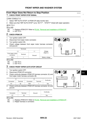
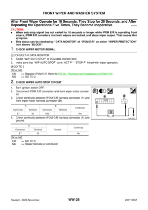
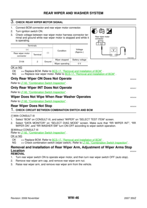
2. CHECK WIPER AUTO STOP CIRCUIT
1. Turn ignition switch OFF.
2. Disconnect IPDM E/R connector and front wiper motor connec-
tor.
3. Check continuity between IPDM E/R harness connector (A) and
front wiper motor harness connector (B).
4. Check continuity between IPDM E/R harness connector (A) and
ground.
OK or NG
OK >> GO TO 3.
NG >> Repair harness or connector.
AB
Continuity
Connector Terminal Connector Terminal
E7 32 E52 1 Yes
A
Ground Continuity
Connector Terminal
E7 32 No
SKIB7688E
Page 29 of 54

FRONT WIPER AND WASHER SYSTEM
WW-29
C
D
E
F
G
H
I
J
L
MA
B
WW
Revision: 2006 November2007 350Z
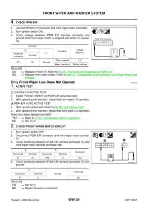
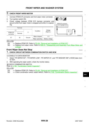
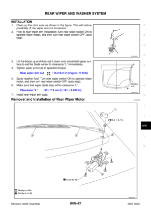
3. CHECK FRONT WIPER MOTOR
1. Connect IPDM E/R connector and front wiper motor connector.
2. Turn ignition switch ON.
3. Check voltage between IPDM E/R harness connector and
ground while front wiper motor is stopped and while it is operat-
ing.
OK or NG
OK >> Replace IPDM E/R. Refer to PG-26, "Removal and Installation of IPDM E/R" .
NG >> Replace front wiper motor. Refer to WW-31, "
Disassembly and Assembly Front Wiper Motor and
Linkage" .
Front Wiper Does Not StopNKS0052K
1. CHECK CIRCUIT BETWEEN COMBINATION SWITCH AND BCM
CONSULT-III DATA MONITOR
1. Select “FR WIPER INT”, “FR WIPER LOW”, “FR WIPER HI”, and “FR WASHER SW” of BCM data moni-
tor item.
2. With operating the wiper switch, check the monitor status.
CHECK COMBINATION SWITCH
Refer to LT- 9 2 , "
Combination Switch Inspection" .
OK or NG
OK >> Replace IPDM E/R. Refer to PG-26, "Removal and Installation of IPDM E/R" .
NG >> Check combination switch (wiper switch). Refer to LT- 9 2 , "
Combination Switch Inspection" .
Terminal
ConditionVoltage
(Approx.) (+)
(-)
IPDM E/R
connectorTerminal
E7 32 GroundWiper stopped 0 V
Wiper operating Battery voltage
SKIA5303E
Page 30 of 54

WW-30
FRONT WIPER AND WASHER SYSTEM
Revision: 2006 November2007 350Z
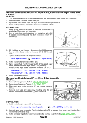
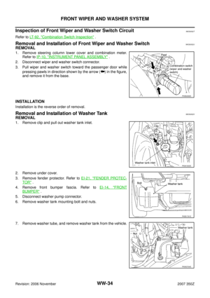
Removal and Installation of Front Wiper Arms, Adjustment of Wiper Arms Stop
Location
NKS0052L
REMOVAL
1. Turn front wiper switch ON to operate wiper motor, and then turn front wiper switch OFF (auto stop).
2. Remove washer tube from washer tube joint.
3. Open hood, remove front wiper arm caps, and remove front wiper arm nuts.
4. Raise front wiper arms, and remove front wiper arms from vehicle.
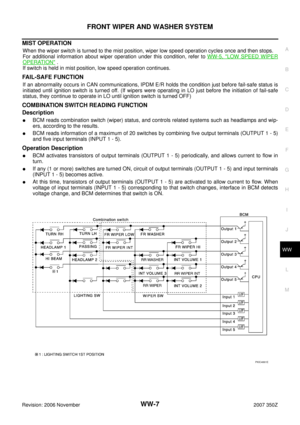
INSTALLATION
1. Clean up the pivot area as shown in the figure. This will reduce
possibility of front wiper arm looseness.
2. Prior to front wiper arms installation, turn front wiper switch ON
to operate wiper motor, and then turn front wiper switch OFF
(auto stop).
3. Lift the blade up and then set it down onto windshield glass sur-
face to set the blade center to clearance “L1” & “L2” immedi-
ately.
4. Tighten front wiper arm nuts to specified torque.
5. Install washer tube from washer tube joint.
6. Spray washer fluid. Turn front wiper switch ON to operate wiper
motor, and then turn front wiper switch OFF (auto stop).
7. Make sure that wiper blades stop within clearance “L1” & “L2”.
8. Install front wiper arm caps.
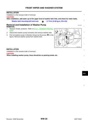
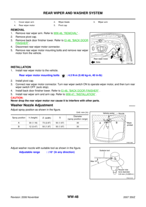
Removal and Installation of Front Wiper Drive AssemblyNKS0052M
REMOVAL
1. Remove front wiper arms. Refer to WW-30, "REMOVAL" .
2. Remove cowl top cover. Refer to EI-20, "
COWL TOP" .
3. Disconnect wiper motor connector (1) and remove connector
clip (A).
4. Remove front wiper drive assembly mounting bolts (B), and
remove front wiper drive assembly (2) from the vehicle.
INSTALLATION
1. Install front wiper drive assembly to the vehicle.
2. Connect wiper motor connector. Turn front wiper switch ON to operate wiper motor, and then turn front
wiper switch OFF (auto stop).
3. Install connector clips to the wiper frame, and install cowl top cover. Refer to EI-20, "
COWL TOP" .
SEL024J
Front wiper arm nuts : 23.6 N·m (2.4 kg-m, 18 ft-lb)
Clearance “L1” : 63.9 ± 7.5 mm (2.516 ± 0.295 in)
Clearance “L2” : 32.0 ± 6.5 mm (1.260 ± 0.256 in)
PKIA9951E
SKIB7455E
Front wiper drive assembly mounting bolts : 4.5 N·m (0.46 kg-m, 40 in-lb)
Page 31 of 54

FRONT WIPER AND WASHER SYSTEM
WW-31
C
D
E
F
G
H
I
J
L
MA
B
WW
Revision: 2006 November2007 350Z
4. Install front wiper arms and arm caps. Refer to WW-30, "INSTALLATION" .
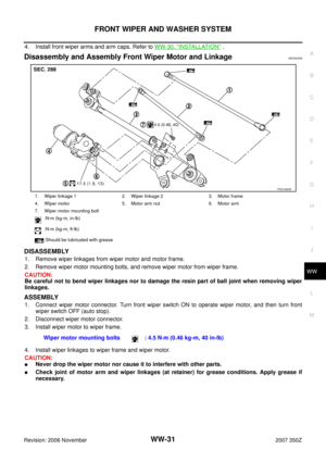
Disassembly and Assembly Front Wiper Motor and LinkageNKS0052N
DISASSEMBLY
1. Remove wiper linkages from wiper motor and motor frame.
2. Remove wiper motor mounting bolts, and remove wiper motor from wiper frame.
CAUTION:
Be careful not to bend wiper linkages nor to damage the resin part of ball joint when removing wiper
linkages.
ASSEMBLY
1. Connect wiper motor connector. Turn front wiper switch ON to operate wiper motor, and then turn front
wiper switch OFF (auto stop).
2. Disconnect wiper motor connector.
3. Install wiper motor to wiper frame.
4. Install wiper linkages to wiper frame and wiper motor.
CAUTION:
�Never drop the wiper motor nor cause it to interfere with other parts.
�Check joint of motor arm and wiper linkages (at retainer) for grease conditions. Apply grease if
necessary.
1. Wiper linkage 1 2. Wiper linkage 2 3. Motor frame
4. Wiper motor 5. Motor arm nut 6. Motor arm
7. Wiper motor mounting bolt
:N·m (kg-m, in-lb)
:N·m (kg-m, ft-lb)
:Should be lubricated with grease
PKIC4863E
Wiper motor mounting bolts : 4.5 N·m (0.46 kg-m, 40 in-lb)
Page 32 of 54
WW-32
FRONT WIPER AND WASHER SYSTEM
Revision: 2006 November2007 350Z
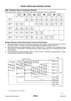
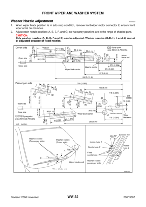
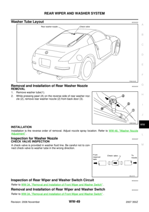
Washer Nozzle AdjustmentNKS0052O
1. When wiper blade position is in auto stop condition, remove front wiper motor connector to ensure front
wiper arms do not move.
2. Adjust each nozzle position (A, B, E, F, and G) so that spray positions are in the range of shaded parts.
CAUTION:
Only washer nozzles (A, B, E, F, and G) can be adjusted. Washer nozzles (C, D, H, I, and J) cannot
be adjusted because of fixed nozzles.
PKIB1781E