Page 17 of 54

FRONT WIPER AND WASHER SYSTEM
WW-17
C
D
E
F
G
H
I
J
L
MA
B
WW
Revision: 2006 November2007 350Z
Terminals and Reference Values for IPDM E/RNKS00526
How to Proceed With Trouble DiagnosisNKS00527
1. Confirm the symptoms and customer complaint.
2. Understand operation description and function description. Refer to WW-4, "
System Description" .
3. Perform preliminary check. Refer to WW-18, "
Preliminary Check" .
4. Check symptom and repair or replace the cause of malfunction.
5. Does the front wiper and washer operate normally? If YES, GO TO 6. If NO, GO TO 4.
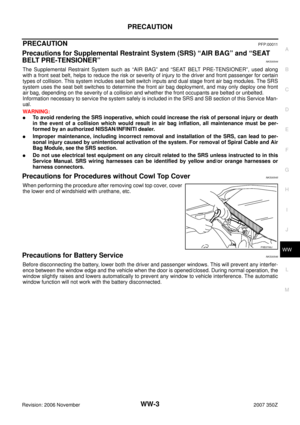
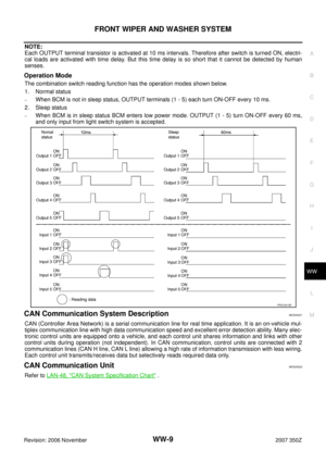
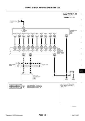
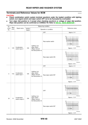
36 W/RCombination
switch output 1ONLighting, turn,
wiper switch
(Wiper intermit-
tent dial position 4)OFF
Approx. 7.2 V
Any of the conditions below
�Front wiper switch MIST
�Front wiper switch LO
�Front washer switch
Approx. 1.2 V
38 W/LIgnition switch
(ON) ON — Battery voltage
39 L CAN − H— — —
40 P CAN − L— — —
42 GYBattery power
supplyOFF — Battery voltage
52 B Ground ON — Approx. 0 V
55 RBattery power
supplyOFF — Battery voltage Te r -
minal
No.Wire
colorSignal nameMeasuring condition
Reference value
Ignition
switchOperation or condition
PKIB4960J
PKIB4958J
Terminal
No.Wire
colorSignal nameMeasuring condition
Reference value
Ignition
switchOperation or condition
21 L Low speed signal ON Wiper switchOFF Approx. 0 V
LOW Battery voltage
31 L/B High speed signal ON Wiper switchOFF Approx. 0 V
HI Battery voltage
32 L/Y Wiper auto stop signal ONWiper operating Battery voltage
Wiper stopped Approx. 0 V
38 B Ground ON — Approx. 0 V
44 OR Washer pump power supply ON — Battery voltage
48 L CAN − H—— —
49 P CAN − L—— —
60 B Ground ON — Approx. 0 V
Page 18 of 54

WW-18
FRONT WIPER AND WASHER SYSTEM
Revision: 2006 November2007 350Z
6. INSPECTION END
Preliminary CheckNKS00528
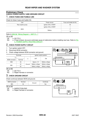
CHECK POWER SUPPLY AND GROUND CIRCUIT
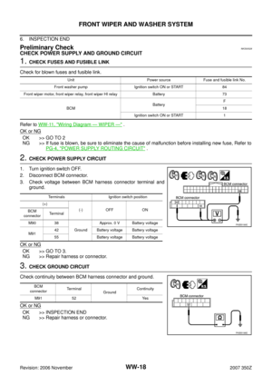
1. CHECK FUSES AND FUSIBLE LINK
Check for blown fuses and fusible link.
Refer to WW-11, "
Wiring Diagram — WIPER —" .
OK or NG
OK >> GO TO 2
NG >> If fuse is blown, be sure to eliminate the cause of malfunction before installing new fuse, Refer to
PG-4, "
POWER SUPPLY ROUTING CIRCUIT" .
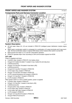
2. CHECK POWER SUPPLY CIRCUIT
1. Turn ignition switch OFF.
2. Disconnect BCM connector.
3. Check voltage between BCM harness connector terminal and
ground.
OK or NG
OK >> GO TO 3.
NG >> Repair harness or connector.
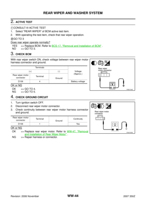
3. CHECK GROUND CIRCUIT
Check continuity between BCM harness connector and ground.
OK or NG
OK >> INSPECTION END
NG >> Repair harness or connector.
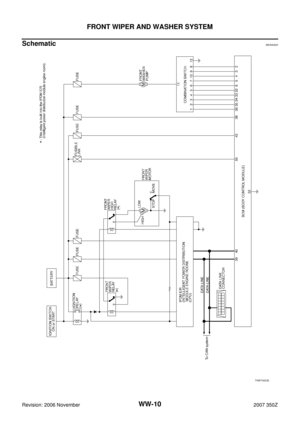
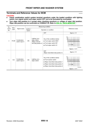
Unit Power source Fuse and fusible link No.
Front washer pump Ignition switch ON or START 84
Front wiper motor, front wiper relay, front wiper HI relay Battery 73
BCMBatteryF
18
Ignition switch ON or START 1
Terminals Ignition switch position
(+)
(-) OFF ON
BCM
connectorTerminal
M90 38
GroundApprox. 0 V Battery voltage
M9142 Battery voltage Battery voltage
55 Battery voltage Battery voltage
PKIB5199E
BCM
connectorTe r m i n a l
GroundContinuity
M91 52 Yes
PKIB5198E
Page 19 of 54
NKS00529
CONSULT-III can display each diagnostic item using the diagnostic test")
FRONT WIPER AND WASHER SYSTEM
WW-19
C
D
E
F
G
H
I
J
L
MA
B
WW
Revision: 2006 November2007 350Z
CONSULT-III Function (BCM)NKS00529
CONSULT-III can display each diagnostic item using the diagnostic test mode shown following.
WORK SUPPORT
Display Item List
NOTE:
Regarding wiper speed setting, if the BCM set value is initialized by the use of CONSULT-III work support,
then set it individually to OFF after the initialization because it is automatically set to ON by initializing CON-
SULT-III.
DATA MONITOR
Display Item List
NOTE:
1. Coupe models
2. This item is displayed, but cannot be monitored.
ACTIVE TEST
Display Item List
BCM diagnosis position Diagnosis mode Description
WIPERWORK SUPPORT Changes the setting for each function.
DATA MONITOR Displays BCM input data in real time.
ACTIVE TEST Device operation can be checked by applying a drive signal to device.
BCMSELF-DIAG RESULTS BCM performs self-diagnosis of CAN communication.
CAN DIAG SUPPORT MNTR The result of transmit/receive diagnosis of CAN communication can be read.
Item Description CONSULT-III Factory setting
WIPER SPEED
SETTINGVehicle speed sousing type wiper control mode can be changed in this
mode. Vehicle speed sousing type wiper control mode between two ON/OFF.ON —
OFF×
Monitor item Contents
IGN ON SW “ON/OFF”Displays “ignition switch ON (ON)/Other OFF or ACC (OFF)” status as judged from ignition
switch signal.
IGN SW CAN “ON/OFF”Displays “ignition switch ON (ON)/Other OFF or ACC (OFF)” status as judged from CAN com-
munication signal.
FR WIPER HI “ON/OFF” Displays “FRONT WIPER HI (ON)/Other (OFF)” status as judged from wiper switch signal.
FR WIPER LOW “ON/OFF” Displays “FRONT WIPER LOW (ON)/Other (OFF)” status as judged from wiper switch signal.
FR WIPER INT “ON/OFF” Displays “FRONT WIPER INT (ON)/Other (OFF)” status as judged from wiper switch signal.
FR WASHER SW “ON/OFF”Displays “FRONT WASHER Switch (ON)/Other (OFF)” status as judged from wiper switch
signal.
INT VOLUME “1 - 7” Displays intermittent operation dial position setting (1 - 7) as judged from wiper switch signal.
FR WIPER STOP “ON/OFF” Displays “Stopped (ON)/Operating (OFF)” status as judged from auto-stop signal.
VEHICLE SPEED “km/h” Displays vehicle speed status as judged from vehicle speed signal.
RR WIPER ON
NOTE 1“ON/OFF” Displays “Rear Wiper ON (ON)/Other (OFF)” status as judged from wiper switch signal.
RR WIPER INT
NOTE 1“ON/OFF” Displays “Rear Wiper INT (ON)/Other (OFF)” status as judged from wiper switch signal.
RR WASHER SW
NOTE 1“ON/OFF” Displays “Rear Washer Switch (ON)/Other (OFF)” status as judged from wiper switch signal.
RR WIPER STOP
NOTE 1“ON/OFF” Displays “Rear Wiper Stop (ON)/Other (OFF)” status, as judged from wiper switch signal.
RR WIPER STP2
NOTE 2“OFF” —
Test item Display on CONSULT-III screen Description
Front wiper output FR WIPER With a certain operation (OFF, HI, LO, INT), front wiper can be operated.
Rear wiper output
NOTERR WIPER Rear wiper can be operated by ON−OFF operation.
Page 20 of 54
NKS0052A
CONSULT-III can display each diagnostic item using the diagnostic test m")
WW-20
FRONT WIPER AND WASHER SYSTEM
Revision: 2006 November2007 350Z
NOTE:
Coupe models
CONSULT-III Function (IPDM E/R)NKS0052A
CONSULT-III can display each diagnostic item using the diagnostic test mode shown following.
DATA MONITOR
All Signals, Main Signals, Selection From Menu
NOTE:
Perform monitoring of IPDM E/R data with ignition switch ON. When ignition switch is at ACC, the display may
not be correct.
ACTIVE TEST
Display Item List
Diagnosis Mode Description
SELF−DIAG RESULTS Refer to PG-18, "
SELF-DIAG RESULTS" .
DATA MONITOR The input/output data of IPDM E/R is displayed in real time.
CAN DIAG SUPPORT MNTR The result of transmit/receive diagnosis of CAN communication can be read.
ACTIVE TEST IPDM E/R sends a drive signal to electronic components to check their operation.
Item nameCONSULT-III
screen displayDisplay or unitMonitor item selection
Description
ALL
SIGNALSMAIN
SIGNALSSELECTION
FROM MENU
FR wiper request FR WIP REQ STOP/LOW/HI×× ×Signal status input from BCM
Wiper auto stop WIP AUTO STOP ACT P/STOP P×× ×Output status of IPDM E/R
Wiper protection WIP PROT OFF/Block×× ×Control status of IPDM E/R
Test item CONSULT-III screen display Description
Front wiper (HI, LO) output FR WIPERWith a certain operation (OFF, HI ON, LO ON), front wiper relay (and/or
front wiper high relay) can be operated.
Page 21 of 54

FRONT WIPER AND WASHER SYSTEM
WW-21
C
D
E
F
G
H
I
J
L
MA
B
WW
Revision: 2006 November2007 350Z
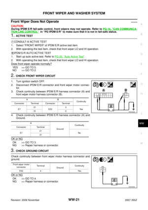
Front Wiper Does Not OperateNKS0052B
CAUTION:
During IPDM E/R fail-safe control, front wipers may not operate. Refer to PG-16, "
CAN COMMUNICA-
TION LINE CONTROL" in “PG IPDM E/R” to make sure that it is not in fail-safe status.
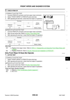
1. ACTIVE TEST
CONSULT-III ACTIVE TEST
1. Select "FRONT WIPER" of IPDM E/R active test item.
2. With operating the test item, check that front wiper LO and HI operation.
IPDM E/R AUTO ACTIVE TEST
1. Start up auto active test. Refer to PG-20, "
Auto Active Test" .
2. With operating the test item, check that front wiper LO and HI operation.
Does front wiper operate normally?
YES >> GO TO 5.
NO >> GO TO 2.
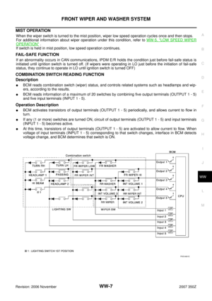
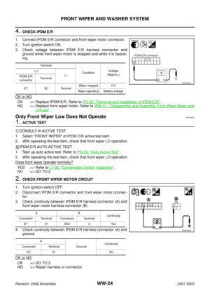
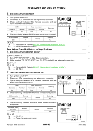
2. CHECK FRONT WIPER CIRCUIT
1. Turn ignition switch OFF.
2. Disconnect IPDM E/R connector and front wiper motor connec-
tor.
3. Check continuity between IPDM E/R harness connector (A) and
front wiper motor harness connector (B).
4. Check continuity between IPDM E/R harness connector (A) and
Ground.
OK or NG
OK >> GO TO 3.
NG >> Repair harness or connector.
3. CHECK GROUND CIRCUIT
Check continuity between front wiper motor harness connector and
ground.
OK or NG
OK >> GO TO 4.
NG >> Repair harness or connector.
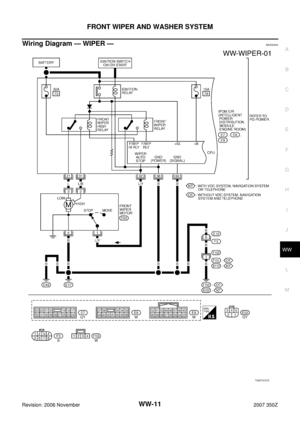
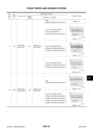
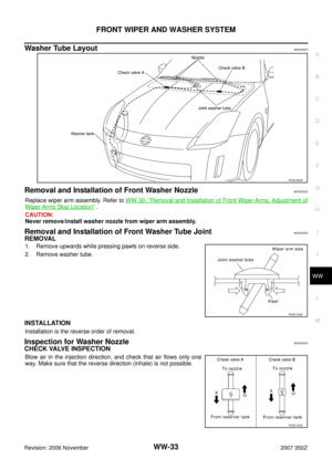
AB
Continuity
Connector Terminal Connector Terminal
E721
E523
Ye s
31 2
A
GroundContinuity
Connector Terminal
E721
No
31
SKIB7682E
Front wiper motor
connectorTerminal
Ground Continuity
E52 4 Yes
SKIB7683E
Page 22 of 54

WW-22
FRONT WIPER AND WASHER SYSTEM
Revision: 2006 November2007 350Z
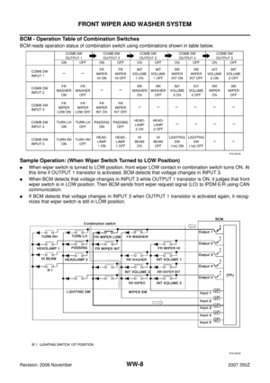
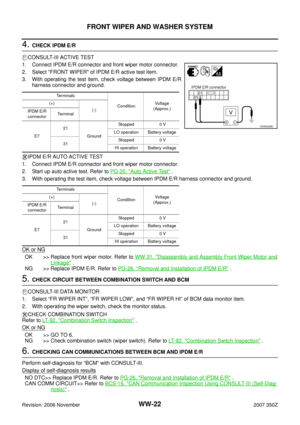
4. CHECK IPDM E/R
CONSULT-III ACTIVE TEST
1. Connect IPDM E/R connector and front wiper motor connector.
2. Select "FRONT WIPER" of IPDM E/R active test item.
3. With operating the test item, check voltage between IPDM E/R
harness connector and ground.
IPDM E/R AUTO ACTIVE TEST
1. Connect IPDM E/R connector and front wiper motor connector.
2. Start up auto active test. Refer to PG-20, "
Auto Active Test" .
3. With operating the test item, check voltage between IPDM E/R harness connector and ground.
OK or NG
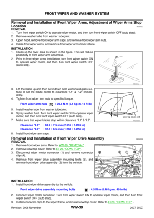
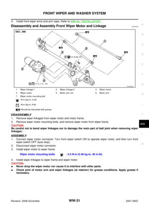
OK >> Replace front wiper motor. Refer to WW-31, "Disassembly and Assembly Front Wiper Motor and
Linkage" .
NG >> Replace IPDM E/R. Refer to PG-26, "
Removal and Installation of IPDM E/R" .
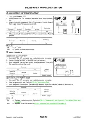
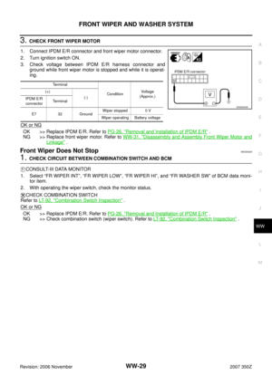
5. CHECK CIRCUIT BETWEEN COMBINATION SWITCH AND BCM
CONSULT-III DATA MONITOR
1. Select “FR WIPER INT”, “FR WIPER LOW”, and “FR WIPER HI” of BCM data monitor item.
2. With operating the wiper switch, check the monitor status.
CHECK COMBINATION SWITCH
Refer to LT- 9 2 , "
Combination Switch Inspection" .
OK or NG
OK >> GO TO 6.
NG >> Check combination switch (wiper switch). Refer to LT- 9 2 , "
Combination Switch Inspection" .
6. CHECKING CAN COMMUNICATIONS BETWEEN BCM AND IPDM E/R
Perform self-diagnosis for “BCM” with CONSULT-III.
Display of self-diagnosis results
NO DTC>> Replace IPDM E/R. Refer to PG-26, "Removal and Installation of IPDM E/R" .
CAN COMM CIRCUIT>> Refer to BCS-16, "
CAN Communication Inspection Using CONSULT-III (Self-Diag-
nosis)" .
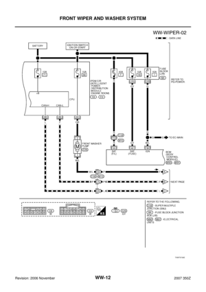
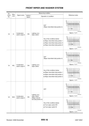
Te r m i n a l s
ConditionVoltage
(Approx.) (+)
(-)
IPDM E/R
connectorTerminal
E721
GroundStopped 0 V
LO operation Battery voltage
31Stopped 0 V
HI operation Battery voltage
Te r m i n a l s
ConditionVoltage
(Approx.) (+)
(-)
IPDM E/R
connectorTerminal
E721
GroundStopped 0 V
LO operation Battery voltage
31Stopped 0 V
HI operation Battery voltage
SKIA5298E
Page 23 of 54

FRONT WIPER AND WASHER SYSTEM
WW-23
C
D
E
F
G
H
I
J
L
MA
B
WW
Revision: 2006 November2007 350Z
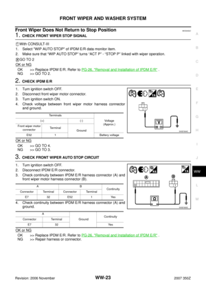
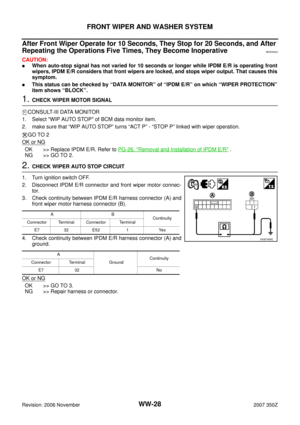
Front Wiper Does Not Return to Stop PositionNKS0052C
1. CHECK FRONT WIPER STOP SIGNAL
With CONSULT-III
1. Select "WIP AUTO STOP" of IPDM E/R data monitor item.
2. Make sure that “WIP AUTO STOP” turns “ACT P” - “STOP P” linked with wiper operation.
GO TO 2
OK or NG
OK >> Replace IPDM E/R. Refer to PG-26, "Removal and Installation of IPDM E/R" .
NG >> GO TO 2.
2. CHECK IPDM E/R
1. Turn ignition switch OFF.
2. Disconnect front wiper motor connector.
3. Turn ignition switch ON.
4. Check voltage between front wiper motor harness connector
and ground.
OK or NG
OK >> GO TO 4.
NG >> GO TO 3.
3. CHECK FRONT WIPER AUTO STOP CIRCUIT
1. Turn ignition switch OFF.
2. Disconnect IPDM E/R connector.
3. Check continuity between IPDM E/R harness connector (A) and
front wiper motor harness connector (B).
4. Check continuity between IPDM E/R harness connector (A) and
ground.
OK or NG
OK >> Replace IPDM E/R. Refer to PG-26, "Removal and Installation of IPDM E/R" .
NG >> Repair harness or connector.
Te r m i n a l s
Voltage
(Approx.) (+) (-)
Front wiper motor
connectorTe r m i n a l
Ground
E52 1 Battery voltage
SKIB7684E
AB
Continuity
Connector Terminal Connector Terminal
E7 32 E52 1 Yes
A
GroundContinuity
Connector Terminal
E7 32 Yes
SKIB7685E
Page 24 of 54

WW-24
FRONT WIPER AND WASHER SYSTEM
Revision: 2006 November2007 350Z
4. CHECK IPDM E/R
1. Connect IPDM E/R connector and front wiper motor connector.
2. Turn ignition switch ON.
3. Check voltage between IPDM E/R harness connector and
ground while front wiper motor is stopped and while it is operat-
ing.
OK or NG
OK >> Replace IPDM E/R. Refer to PG-26, "Removal and Installation of IPDM E/R" .
NG >> Replace front wiper motor. Refer to WW-31, "
Disassembly and Assembly Front Wiper Motor and
Linkage" .
Only Front Wiper Low Does Not OperateNKS0052D
1. ACTIVE TEST
CONSULT-III ACTIVE TEST
1. Select "FRONT WIPER" of IPDM E/R active test item.
2. With operating the test item, check that front wiper LO operation.
IPDM E/R AUTO ACTIVE TEST
1. Start up auto active test. Refer to PG-20, "
Auto Active Test" .
2. With operating the test item, check that front wiper LO operation.
Does front wiper operate normally?
YES >> Refer to LT- 9 2 , "Combination Switch Inspection" .
NO >> GO TO 2.
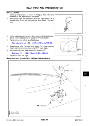
2. CHECK FRONT WIPER MOTOR CIRCUIT
1. Turn ignition switch OFF.
2. Disconnect IPDM E/R connector and front wiper motor connec-
tor.
3. Check continuity between IPDM E/R harness connector (A) and
front wiper motor harness connector (B).
4. Check continuity between IPDM E/R harness connector (A) and
ground.
OK or NG
OK >> GO TO 3.
NG >> Repair harness or connector.
Terminal
ConditionVoltage
(Approx.) (+)
(-)
IPDM E/R
connectorTerminal
E7 32 GroundWiper stopped 0 V
Wiper operating Battery voltage
SKIA5303E
AB
Continuity
Connector Terminal Connector Terminal
E7 21 E52 3 Yes
A
Ground Continuity
Connector Terminal
E7 21 No
SKIB7686E