Page 17 of 30

STARTING SYSTEM
SC-17
C
D
E
F
G
H
I
J
L
MA
B
SC
Revision: 2006 November2007 350Z
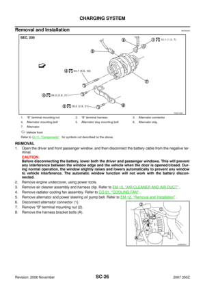
Removal and InstallationNKS0000C
REMOVAL
1. Open the driver and front passenger window, and then disconnect the battery cable from the negative ter-
minal.
CAUTION:
Before disconnecting the battery, lower both the driver and passenger windows. This will prevent
any interference between the window edge and the vehicle when the door is opened/closed. Dur-
ing normal operation, the window slightly raises and lowers automatically to prevent any window
to vehicle interference. The automatic window function will not work with the battery discon-
nected.
2. Remove engine undercover, using power tools.
3. Disconnect steering lower joint (1), then remove it. Refer to PS-
17, "REMOVAL" .
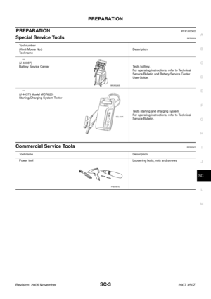
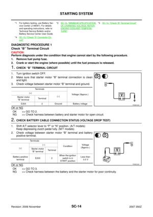
4. Remove “B” terminal mounting nut (A).
1. “B” terminal mounting nut 2. “B” terminal harness 3. Starter motor
4. Transmission case (M/T models)
Converter housing (A/T models)5. Harness clip bracket 6. “S” terminal connector
7. Starter motor mounting bolt
: Vehicle front
Refer to GI-11, "
Components" for symbols not described on the above.
PKID1228E
PKID1141E
Page 18 of 30
SC-18
STARTING SYSTEM
Revision: 2006 November2007 350Z
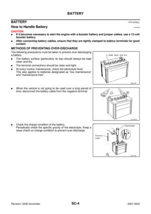
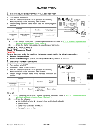
5. Disconnect “S” connector (B).
6. Remove starter motor mounting bolts (A) and harness connector
clip bracket, using power tools.
7. Remove starter motor (1) downward from the vehicle.
INSTALLATION
Installation is the reverse order of removal.
CAUTION:
Be sure to tighten “B” terminal nut carefully.
PKID1142E
PKID1143E
Page 19 of 30

STARTING SYSTEM
SC-19
C
D
E
F
G
H
I
J
L
MA
B
SC
Revision: 2006 November2007 350Z
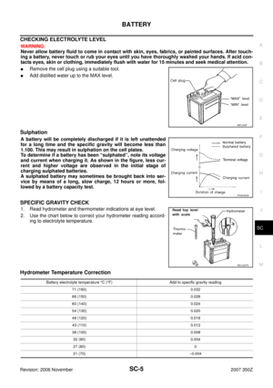
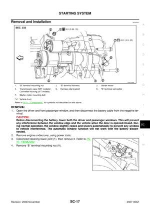
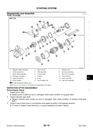
Disassembly and Assembly NKS0000D
TYPE: S114-928
INSPECTION AFTER DISASSEMBLY
Pinion/Clutch Check
1. Inspect pinion teeth.
�Replace pinion if teeth are worn or damaged. (Also check condition of ring gear teeth.)
2. Inspect reduction gear teeth.
�Replace reduction gear if teeth are worn or damaged. (Also check condition of armature shaft gear
teeth.)
3. Check to see if pinion locks in one direction and rotates smoothly in the opposite direction.
�If it locks or rotates in both directions, or unusual resistance is evident, replace.
1. Magnetic switch assembly 2. Dust cover kit 3. Shift lever set
4. Center bracket (A) 5. Yoke assembly 6. Armature assembly
7. Brush holder assembly 8. Thrust washer 9. Rear cover assembly
10. Shaft gear assembly 11. Packing 12. Thrust washer
13. Center bracket (P) 14. E-ring 15. Pinion assembly
16. Pinion stopper 17. Pinion stopper clip 18. Gear case assembly
: High-temperature grease point
Refer to GI-11, "
Components" for symbols not described on the above.
PKID1140E
Page 20 of 30

SC-20
CHARGING SYSTEM
Revision: 2006 November2007 350Z
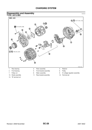
CHARGING SYSTEMPFP:23100
System DescriptionNKS0000E
The alternator provides DC voltage to operate the vehicle's electrical system and to keep the battery charged.
The voltage output is controlled by the IC regulator.
Power is supplied at all times
�through 10A fuse (No. 36, located in the fuse and fusible link block)
�to alternator terminal 4 (“S” terminal).
“B” terminal supplies power to charge the battery and operate the vehicle's electrical system. Output voltage is
controlled by the IC regulator at terminal 4 (“S” terminal) detecting the input voltage.
The charging circuit is protected by the 140A fusible link (letter A , located in the fusible link holder).
The alternator is grounded to the engine block.
With the ignition switch in the ON or START position, power is supplied
�through 10A fuse [No. 14, located in the fuse block (J/B)]
�to combination meter terminal 23 for the charge warning lamp.
Ground is supplied with power and ground supplied
�to terminal 17 of combination meter
�through alternator terminal 3 (“L” terminal)
�through case ground.
The charge warning lamp will illuminate. When the alternator is providing sufficient voltage with the engine
running, the ground is opened and the charge warning lamp will go off.
If the charge warning lamp illuminates with the engine running, a malfunction is indicated.
MALFUNCTION INDICATOR
The IC regulator warning function activates to illuminate charge warning lamp, if any of the following symp-
toms occur while alternator is operating:
�Excessive voltage is produced.
�No voltage is produced.
Page 21 of 30
CHARGING SYSTEM
SC-21
C
D
E
F
G
H
I
J
L
MA
B
SC
Revision: 2006 November2007 350Z
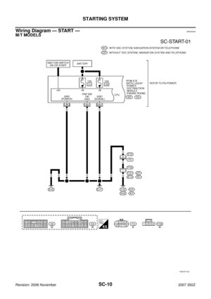
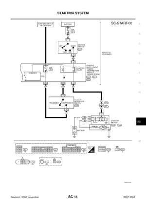
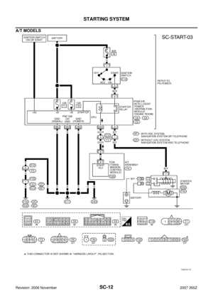
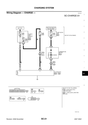
Wiring Diagram — CHARGE —NKS0000F
TKWT5718E
Page 22 of 30
SC-22
CHARGING SYSTEM
Revision: 2006 November2007 350Z
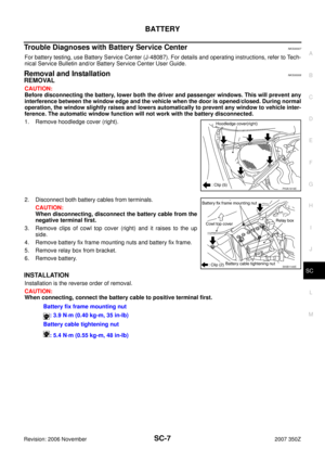
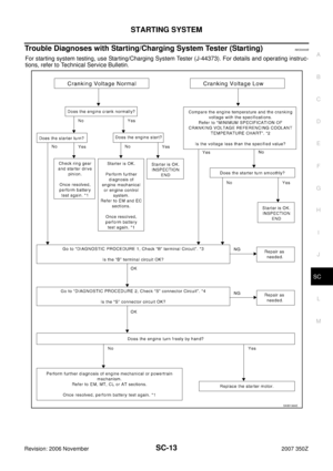
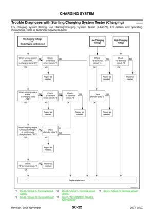
Trouble Diagnoses with Starting/Charging System Tester (Charging)NKS0000G
For charging system testing, use Starting/Charging System Tester (J-44373). For details and operating
instructions, refer to Technical Service Bulletin.
*1SC-23, "Check “L” Terminal Circuit
(Open)"
*2SC-24, "Check “L” Terminal Circuit
(Short)"
*3SC-24, "Check “S” Terminal Circuit"
*4SC-24, "Check “B” Terminal Circuit"*5SC-27, "ALTERNATOR PULLEY
INSPECTION"
SKIB0527E
Page 23 of 30

CHARGING SYSTEM
SC-23
C
D
E
F
G
H
I
J
L
MA
B
SC
Revision: 2006 November2007 350Z
PRELIMINARY INSPECTION
1. CHECK BATTERY TERMINALS CONNECTION
Check if battery terminals are clean and tight.
OK or NG
OK >> GO TO 2.
NG >> Repair battery terminals connection.
2. CHECK FUSE AND FUSIBLE LINK
Check for blown alternator and combination meter fuses and fusible links.
OK or NG
OK >> GO TO 3.
NG >> Be sure eliminate cause of malfunction before installing new fuse and fusible link.
3. CHECK ALTERNATOR DRIVE BELT TENSION
Check alternator drive belt tension. Refer to EM-12, "
Checking Drive Belts" .
OK or NG
OK >> INSPECTION END
NG >> Repair as needed.
DIAGNOSTIC PROCEDURE 1
Check “L” Terminal Circuit (Open)
1. CHECK “L” TERMINAL CONNECTION
1. Turn ignition switch OFF.
2. Check if “L” terminal is clean and tight.
OK or NG
OK >> GO TO 2.
NG >> Repair “L” terminal connection. Confirm repair by performing complete Starting/Charging system
test. Refer to Technical Service Bulletin.
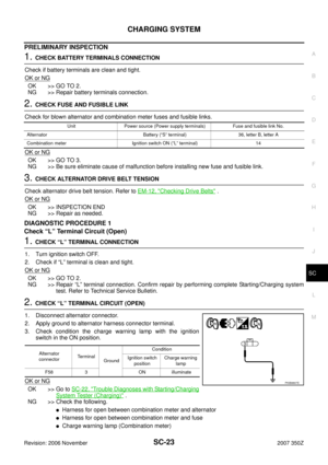
2. CHECK “L” TERMINAL CIRCUIT (OPEN)
1. Disconnect alternator connector.
2. Apply ground to alternator harness connector terminal.
3. Check condition the charge warning lamp with the ignition
switch in the ON position.
OK or NG
OK >> Go to SC-22, "Trouble Diagnoses with Starting/Charging
System Tester (Charging)" .
NG >> Check the following.
�Harness for open between combination meter and alternator
�Harness for open between combination meter and fuse
�Charge warning lamp (Combination meter)
Unit Power source (Power supply terminals) Fuse and fusible link No.
Alternator Battery (“S” terminal) 36, letter B, letter A
Combination meter Ignition switch ON (“L” terminal) 14
Alternator
connectorTerminal
GroundCondition
Ignition switch
positionCharge warning
lamp
F58 3 ON illuminate
PKIB8807E
Page 24 of 30

1. CHECK “L” TERMINAL CIRCUIT (SHORT)
1. Turn ignition switch OFF.
2. Disconnec")
SC-24
CHARGING SYSTEM
Revision: 2006 November2007 350Z
DIAGNOSTIC PROCEDURE 2
Check “L” Terminal Circuit (Short)
1. CHECK “L” TERMINAL CIRCUIT (SHORT)
1. Turn ignition switch OFF.
2. Disconnect alternator connector.
3. Turn ignition switch ON.
Charge warning lamp should light up?
YES >> Check the following.
�Harness for short between combination meter and alternator
�Charge warning lamp (Combination meter)
NO >> Go to SC-22, "
Trouble Diagnoses with Starting/Charging System Tester (Charging)" .
DIAGNOSTIC PROCEDURE 3
Check “S” Terminal Circuit
1. CHECK “S” TERMINAL CONNECTION
1. Turn ignition switch OFF.
2. Check if “S” terminal is clean and tight.
OK or NG
OK >> GO TO 2.
NG >> Repair “S” terminal connection. Confirm repair by performing complete Starting/Charging system
test. Refer to Technical Service Bulletin.
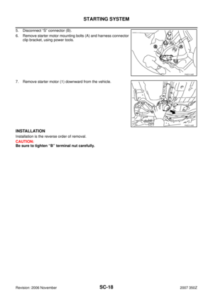
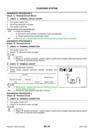
2. CHECK “S” TERMINAL CIRCUIT
1. Disconnect alternator connector.
2. Check voltage between alternator harness connector and
ground.
OK or NG
OK >> Go to SC-22, "Trouble Diagnoses with Starting/Charging
System Tester (Charging)" .
NG >> Harness for open between alternator and fuse.
DIAGNOSTIC PROCEDURE 4
Check “B” Terminal Circuit
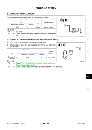
1. CHECK “B” TERMINAL CONNECTION
1. Turn ignition switch OFF.
2. Check if “B” terminal is clean and tight.
OK or NG
OK >> GO TO 2.
NG >> Repair “B” terminal connection. Confirm repair by performing complete Starting/Charging system
test. Refer to Technical Service Bulletin.
Terminals
Voltage (Approx.) (+)
(–)
Alternator connector Terminal
F58 4 Ground Battery voltage
PKIB8808E


.
6. Remove starter motor mounting bolts (A) and harness connector
clip bracket, using power tools.
7. Remove")

NKS0000G
For charging system testing, use Starting/Charging System Tester (J-443")