Page 7 of 30

BATTERY
SC-7
C
D
E
F
G
H
I
J
L
MA
B
SC
Revision: 2006 November2007 350Z
Trouble Diagnoses with Battery Service CenterNKS00007
For battery testing, use Battery Service Center (J-48087). For details and operating instructions, refer to Tech-
nical Service Bulletin and/or Battery Service Center User Guide.
Removal and Installation NKS00008
REMOVAL
CAUTION:
Before disconnecting the battery, lower both the driver and passenger windows. This will prevent any
interference between the window edge and the vehicle when the door is opened/closed. During normal
operation, the window slightly raises and lowers automatically to prevent any window to vehicle inter-
ference. The automatic window function will not work with the battery disconnected.
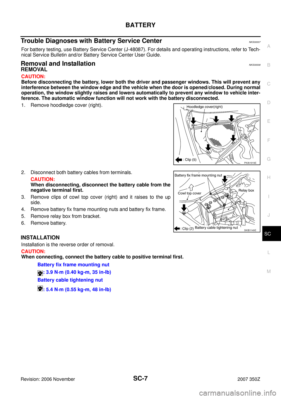
1. Remove hoodledge cover (right).
2. Disconnect both battery cables from terminals.
CAUTION:
When disconnecting, disconnect the battery cable from the
negative terminal first.
3. Remove clips of cowl top cover (right) and it raises to the up
side.
4. Remove battery fix frame mounting nuts and battery fix frame.
5. Remove relay box from bracket.
6. Remove battery.
INSTALLATION
Installation is the reverse order of removal.
CAUTION:
When connecting, connect the battery cable to positive terminal first.
PKIA1919E
SKIB1149E
Battery fix frame mounting nut
: 3.9 N·m (0.40 kg-m, 35 in-lb)
Battery cable tightening nut
: 5.4 N·m (0.55 kg-m, 48 in-lb)
Page 8 of 30

SC-8
STARTING SYSTEM
Revision: 2006 November2007 350Z
STARTING SYSTEMPFP:23300
System Description NKS00009
M/T MODELS
Power is supplied at all times:
�through 40A fusible link (letter M , located in the fuse and fusible link block)
�to ignition switch terminal 1,
�through 10A fuse (No. 71, located in the IPDM E/R)
�to CPU of IPDM E/R,
�through 15A fuse (No. 78, located in the IPDM E/R)
�to CPU of IPDM E/R.
With the ignition switch in the ON or START position, power is supplied:
�to CPU of IPDM E/R, from battery direct
�through 10A fuse (No. 89, located in the IPDM E/R) and IPDM E/R terminal 25
�to clutch interlock switch terminal 1.
When the clutch pedal is depressed, power is supplied:
�through clutch interlock switch terminal 2
�to IPDM E/R terminal 53.
Ground is supplied:
�to IPDM E/R terminals 38, 50 and 60
�from grounds E17, E43 and B102 (with VDC, navigation system or telephone).
�from grounds E17, E43 and F152 (without VDC, navigation system and telephone).
Then starter relay is turn ON.
With the ignition switch in the START position, IPDM E/R is energized and power is supplied:
�from ignition switch terminal 5
�to IPDM E/R terminal 4 and
�through IPDM E/R terminal 3
�to starter motor terminal 1.
The starter motor plunger closes and provides a closed circuit between the battery and starter motor. The
starter motor is grounded to the engine block. With power and ground supplied, cranking occurs and the
engine starts.
Page 9 of 30

STARTING SYSTEM
SC-9
C
D
E
F
G
H
I
J
L
MA
B
SC
Revision: 2006 November2007 350Z
A/T MODELS
Power is supplied at all times:
�through 40A fusible link (letter M , located in the fuse and fusible link block)
�to ignition switch terminal 1,
�through 10A fuse (No. 71, located in the IPDM E/R)
�to CPU of IPDM E/R,
�through 15A fuse (No. 78, located in the IPDM E/R)
�to CPU of IPDM E/R.
With the ignition switch in the ON or START position, power is supplied:
�to CPU of IPDM E/R, from battery direct.
When the selector lever in the “P” or “N” position, power is supplied:
�from A/T assembly (TCM) terminal 9
�to IPDM E/R terminal 53.
Ground is supplied:
�to IPDM E/R terminals 38, 50 and 60
�from grounds E17, E43 and B102 (with VDC, navigation system or telephone).
�from grounds E17, E43 and F152 (without VDC, navigation system and telephone).
Then starter relay is turn ON.
With the ignition switch in the START position, IPDM E/R is energized and power is supplied:
�from ignition switch terminal 5
�to IPDM E/R terminal 4 and
�through IPDM E/R terminal 3
�to starter motor terminal 1.
The starter motor plunger closes and provides a closed circuit between the battery and starter motor. The
starter motor is grounded to the engine block. With power and ground supplied, cranking occurs and the
engine starts.
Page 15 of 30

STARTING SYSTEM
SC-15
C
D
E
F
G
H
I
J
L
MA
B
SC
Revision: 2006 November2007 350Z
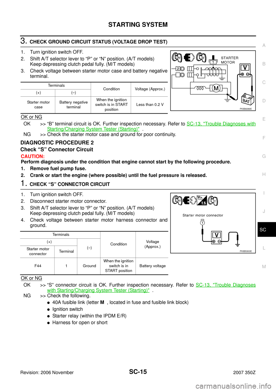
3. CHECK GROUND CIRCUIT STATUS (VOLTAGE DROP TEST)
1. Turn ignition switch OFF.
2. Shift A/T selector lever to “P” or “N” position. (A/T models)
Keep depressing clutch pedal fully. (M/T models)
3. Check voltage between starter motor case and battery negative
terminal.
OK or NG
OK >> “B” terminal circuit is OK. Further inspection necessary. Refer to SC-13, "Trouble Diagnoses with
Starting/Charging System Tester (Starting)" .
NG >> Check the starter motor case and ground for poor continuity.
DIAGNOSTIC PROCEDURE 2
Check “S” Connector Circuit
CAUTION:
Perform diagnosis under the condition that engine cannot start by the following procedure.
1. Remove fuel pump fuse.
2. Crank or start the engine (where possible) until the fuel pressure is released.
1. CHECK “S” CONNECTOR CIRCUIT
1. Turn ignition switch OFF.
2. Disconnect starter motor connector.
3. Shift A/T selector lever to “P” or “N” position. (A/T models)
Keep depressing clutch pedal fully. (M/T models)
4. Check voltage between starter motor harness connector and
ground.
OK or NG
OK >> “S” connector circuit is OK. Further inspection necessary. Refer to SC-13, "Trouble Diagnoses
with Starting/Charging System Tester (Starting)" .
NG >> Check the following.
�40A fusible link (letter M , located in fuse and fusible link block)
�Ignition switch
�Starter relay (within the IPDM E/R)
�Harness for open or short
Terminals
Condition Voltage (Approx.)
(+) (–)
Starter motor
caseBattery negative
terminalWhen the ignition
switch is in START
positionLess than 0.2 V
PKIB6089E
Terminals
ConditionVoltage
(Approx.) (+)
(–)
Starter motor
connectorTerminal
F44 1 GroundWhen the ignition
switch is in
START positionBattery voltage
PKIB5303E