Page 9 of 30

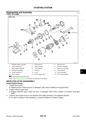
STARTING SYSTEM
SC-9
C
D
E
F
G
H
I
J
L
MA
B
SC
Revision: 2006 November2007 350Z
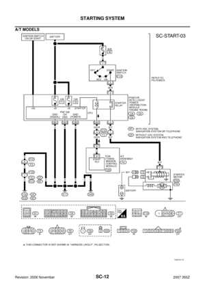
A/T MODELS
Power is supplied at all times:
�through 40A fusible link (letter M , located in the fuse and fusible link block)
�to ignition switch terminal 1,
�through 10A fuse (No. 71, located in the IPDM E/R)
�to CPU of IPDM E/R,
�through 15A fuse (No. 78, located in the IPDM E/R)
�to CPU of IPDM E/R.
With the ignition switch in the ON or START position, power is supplied:
�to CPU of IPDM E/R, from battery direct.
When the selector lever in the “P” or “N” position, power is supplied:
�from A/T assembly (TCM) terminal 9
�to IPDM E/R terminal 53.
Ground is supplied:
�to IPDM E/R terminals 38, 50 and 60
�from grounds E17, E43 and B102 (with VDC, navigation system or telephone).
�from grounds E17, E43 and F152 (without VDC, navigation system and telephone).
Then starter relay is turn ON.
With the ignition switch in the START position, IPDM E/R is energized and power is supplied:
�from ignition switch terminal 5
�to IPDM E/R terminal 4 and
�through IPDM E/R terminal 3
�to starter motor terminal 1.
The starter motor plunger closes and provides a closed circuit between the battery and starter motor. The
starter motor is grounded to the engine block. With power and ground supplied, cranking occurs and the
engine starts.
Page 10 of 30
SC-10
STARTING SYSTEM
Revision: 2006 November2007 350Z
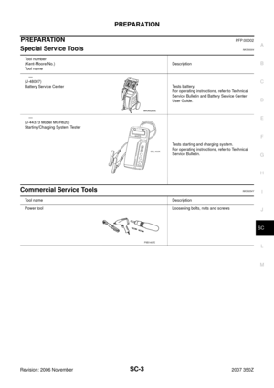
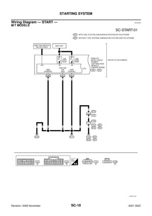
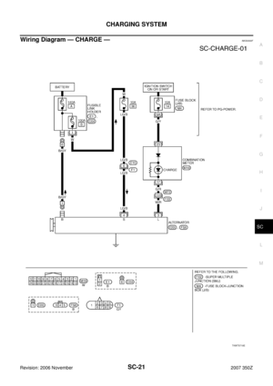
Wiring Diagram — START —NKS0000A
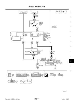
M/T MODELS
TKWT5715E
Page 11 of 30
STARTING SYSTEM
SC-11
C
D
E
F
G
H
I
J
L
MA
B
SC
Revision: 2006 November2007 350Z
TKWT5716E
Page 12 of 30
SC-12
STARTING SYSTEM
Revision: 2006 November2007 350Z
A/T MODELS
TKWT5717E
Page 13 of 30
STARTING SYSTEM
SC-13
C
D
E
F
G
H
I
J
L
MA
B
SC
Revision: 2006 November2007 350Z
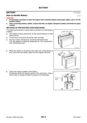
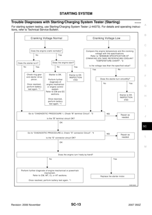
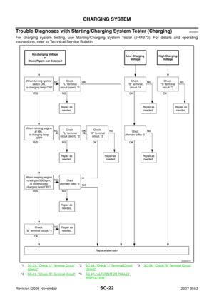
Trouble Diagnoses with Starting/Charging System Tester (Starting)NKS0000B
For starting system testing, use Starting/Charging System Tester (J-44373). For details and operating instruc-
tions, refer to Technical Service Bulletin.
SKIB1369E
Page 14 of 30

SC-14
STARTING SYSTEM
Revision: 2006 November2007 350Z
DIAGNOSTIC PROCEDURE 1
Check “B” Terminal Circuit
CAUTION:
Perform diagnosis under the condition that engine cannot start by the following procedure.
1. Remove fuel pump fuse.
2. Crank or start the engine (where possible) until the fuel pressure is released.
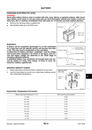
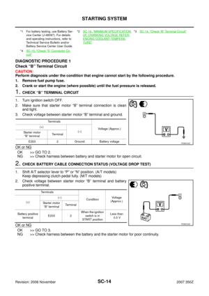
1. CHECK “B” TERMINAL CIRCUIT
1. Turn ignition switch OFF.
2. Make sure that starter motor “B” terminal connection is clean
and tight.
3. Check voltage between starter motor “B” terminal and ground.
OK or NG
OK >> GO TO 2.
NG >> Check harness between battery and starter motor for open circuit.
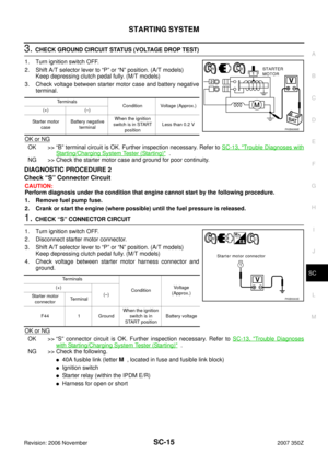
2. CHECK BATTERY CABLE CONNECTION STATUS (VOLTAGE DROP TEST)
1. Shift A/T selector lever to “P” or “N” position. (A/T models)
Keep depressing clutch pedal fully. (M/T models)
2. Check voltage between starter motor “B” terminal and battery
positive terminal.
OK or NG
OK >> GO TO 3.
NG >> Check harness between the battery and the starter motor for poor continuity.
*1 For battery testing, use Battery Ser-
vice Center (J-48087). For details
and operating instructions, refer to
Technical Service Bulletin and/or
Battery Service Center User Guide.*2SC-16, "MINIMUM SPECIFICATION
OF CRANKING VOLTAGE REFER-
ENCING COOLANT TEMPERA-
TURE"
*3SC-14, "Check “B” Terminal Circuit"
*4SC-15, "Check “S” Connector Cir-
cuit"
Te r m i n a l s
Voltage (Approx.) (+)
(–)
Starter motor
“B” terminalTerminal
E203 2 Ground Battery voltage
PKIB8793E
Terminals
ConditionVoltage
(Approx.)
(+)(–)
Starter motor
“B” terminalTerminal
Battery positive
terminalE203 2 When the ignition
switch is in
START positionLess than
0.5 V
PKIB8794E
Page 15 of 30

1. Turn ignition switch OFF.
2. Shift A/T selector lever to “P”")
STARTING SYSTEM
SC-15
C
D
E
F
G
H
I
J
L
MA
B
SC
Revision: 2006 November2007 350Z
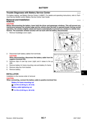
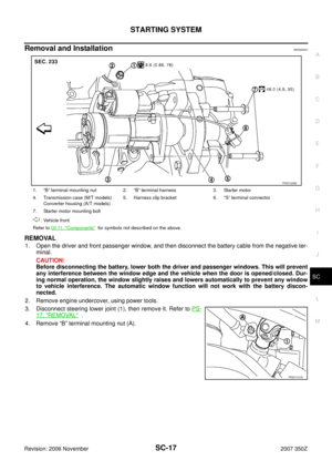
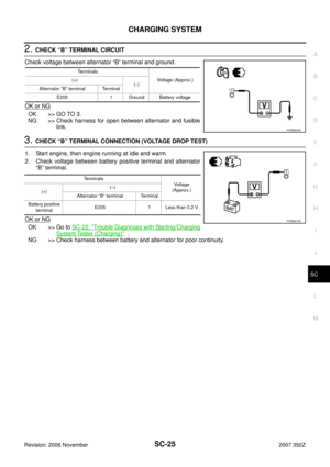
3. CHECK GROUND CIRCUIT STATUS (VOLTAGE DROP TEST)
1. Turn ignition switch OFF.
2. Shift A/T selector lever to “P” or “N” position. (A/T models)
Keep depressing clutch pedal fully. (M/T models)
3. Check voltage between starter motor case and battery negative
terminal.
OK or NG
OK >> “B” terminal circuit is OK. Further inspection necessary. Refer to SC-13, "Trouble Diagnoses with
Starting/Charging System Tester (Starting)" .
NG >> Check the starter motor case and ground for poor continuity.
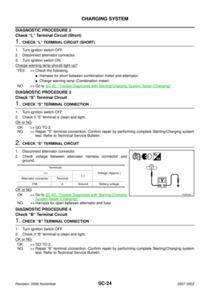
DIAGNOSTIC PROCEDURE 2
Check “S” Connector Circuit
CAUTION:
Perform diagnosis under the condition that engine cannot start by the following procedure.
1. Remove fuel pump fuse.
2. Crank or start the engine (where possible) until the fuel pressure is released.
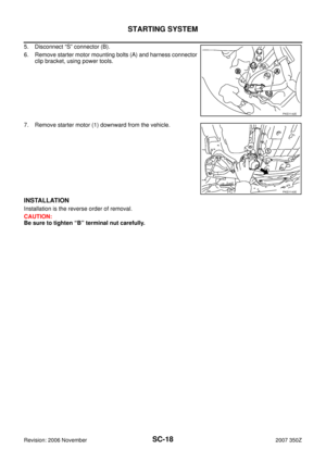
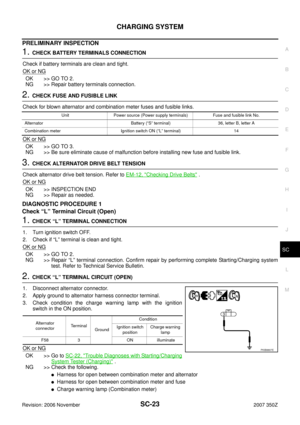
1. CHECK “S” CONNECTOR CIRCUIT
1. Turn ignition switch OFF.
2. Disconnect starter motor connector.
3. Shift A/T selector lever to “P” or “N” position. (A/T models)
Keep depressing clutch pedal fully. (M/T models)
4. Check voltage between starter motor harness connector and
ground.
OK or NG
OK >> “S” connector circuit is OK. Further inspection necessary. Refer to SC-13, "Trouble Diagnoses
with Starting/Charging System Tester (Starting)" .
NG >> Check the following.
�40A fusible link (letter M , located in fuse and fusible link block)
�Ignition switch
�Starter relay (within the IPDM E/R)
�Harness for open or short
Terminals
Condition Voltage (Approx.)
(+) (–)
Starter motor
caseBattery negative
terminalWhen the ignition
switch is in START
positionLess than 0.2 V
PKIB6089E
Terminals
ConditionVoltage
(Approx.) (+)
(–)
Starter motor
connectorTerminal
F44 1 GroundWhen the ignition
switch is in
START positionBattery voltage
PKIB5303E
Page 16 of 30
SC-16
STARTING SYSTEM
Revision: 2006 November2007 350Z
MINIMUM SPECIFICATION OF CRANKING VOLTAGE REFERENCING COOLANT TEMPERA-
TURE
Engine coolant temperature Voltage [V]
−30 °C to −20 °C (−22 °F to −4 °F) 8.6
−19 °C to −10 °C (−2 °F to 14°F) 9.1
−9 °C to 0 °C (16 °F to 32 °F) 9.5
More than 1 °C (More than 34 °F) 9.9


NKS0000B
For starting system testing, use Starting/Cha")
![NISSAN 350Z 2007 Z33 Starting And Charging System Workshop Manual SC-16
STARTING SYSTEM
Revision: 2006 November2007 350Z
MINIMUM SPECIFICATION OF CRANKING VOLTAGE REFERENCING COOLANT TEMPERA-
TURE
Engine coolant temperature Voltage [V]
−30 °C to −20 °C (−22](/manual-img/5/789/w960_789-15.png "NISSAN 350Z 2007 Z33 Starting And Charging System Workshop Manual SC-16
STARTING SYSTEM
Revision: 2006 November2007 350Z
MINIMUM SPECIFICATION OF CRANKING VOLTAGE REFERENCING COOLANT TEMPERA-
TURE
Engine coolant temperature Voltage [V]
−30 °C to −20 °C (−22")