Page 44 of 148

EM-44
FRONT TIMING CHAIN CASE
Revision: 2006 November2007 350Z
FRONT TIMING CHAIN CASEPFP:13599
Removal and InstallationNBS0000Q
NOTE:
�This section describes removal/installation procedure of front timing chain case and timing chain related
parts without removing oil pan (upper) on vehicle.
�When oil pan (upper) needs to be removed or installed, or when rear timing chain case is removed or
installed, remove oil pans (upper and lower) first. Then remove front timing chain case, timing chain
related parts, and rear timing chain case in this order, and install in the reverse order of removal. Refer to
EM-53, "
TIMING CHAIN" .
�Refer to EM-53, "TIMING CHAIN" for component parts location.
REMOVAL
1. Remove engine cover with power tool. Refer to EM-17, "INTAKE MANIFOLD COLLECTOR" .
2. Remove undercover with power tool.
3. Release the fuel pressure. Refer to EC-79, "
FUEL PRESSURE RELEASE" .
4. Disconnect the battery cable from the negative terminal.
5. Drain engine oil. Refer to LU-7, "
Changing Engine Oil" .
CAUTION:
�Perform this step when engine is cold.
�Do not spill engine oil on drive belts.
6. Drain engine coolant from radiator. Refer to CO-10, "
Changing Engine Coolant" .
CAUTION:
�Perform this step when engine is cold.
�Do not spill engine coolant on drive belts.
7. Remove radiator cooling fan assembly. Refer to CO-21, "
COOLING FAN" .
8. Separate engine harnesses removing their brackets from front timing chain case.
9. Remove drive belts. Refer to EM-12, "
DRIVE BELTS" .
10. Remove intake manifold collector. Refer to EM-17, "
INTAKE MANIFOLD COLLECTOR" .
11. Remove harness bracket and fuel sub tube mounting bolt on front timing chain case.
12. Remove oil level gauge and guide.
13. Remove power steering oil pump from bracket with piping connected, and temporarily secure it to aside.
Refer to PS-28, "
POWER STEERING OIL PUMP" .
14. Remove power steering oil pump bracket. Refer to PS-28, "
POWER STEERING OIL PUMP" .
15. Remove alternator. Refer to SC-20, "
CHARGING SYSTEM" .
16. Remove water outlet and water piping. Refer to CO-28, "
WATER OUTLET AND WATER PIPING" .
17. Remove left and right valve timing control covers with the following procedure.
a. Disconnect valve timing control harness connector.
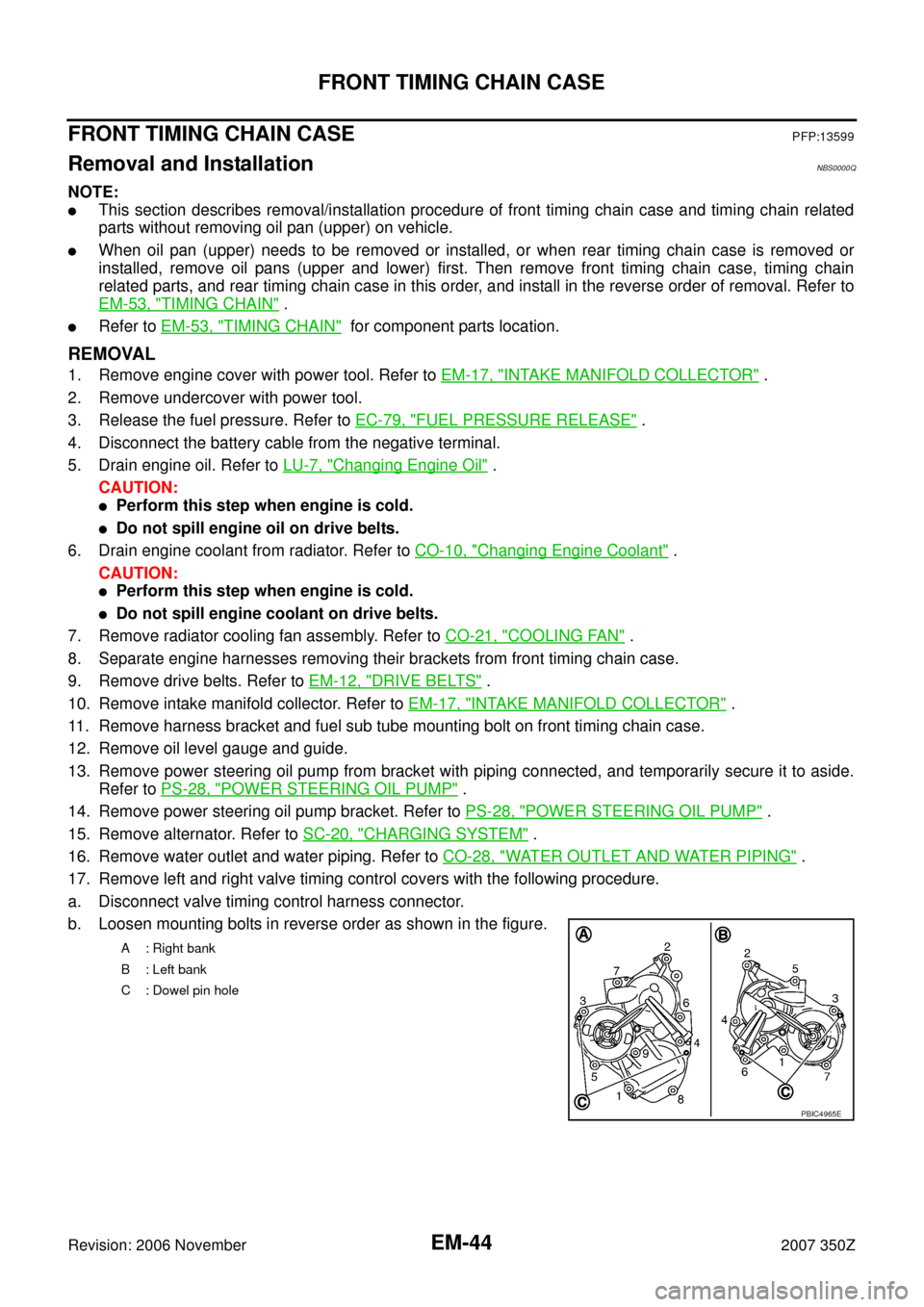
b. Loosen mounting bolts in reverse order as shown in the figure.
A : Right bank
B : Left bank
C : Dowel pin hole
PBIC4965E
Page 89 of 148

CYLINDER HEAD
EM-89
C
D
E
F
G
H
I
J
K
L
MA
EM
Revision: 2006 November2007 350Z
CYLINDER HEADPFP:11041
On-Vehicle ServiceNBS0000Y
CHECKING COMPRESSION PRESSURE
1. Warm up engine thoroughly. Then, stop it.
2. Release fuel pressure. Refer to EC-79, "
FUEL PRESSURE RELEASE" .
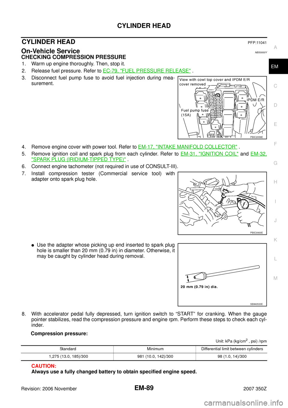
3. Disconnect fuel pump fuse to avoid fuel injection during mea-
surement.
4. Remove engine cover with power tool. Refer to EM-17, "
INTAKE MANIFOLD COLLECTOR" .
5. Remove ignition coil and spark plug from each cylinder. Refer to EM-31, "
IGNITION COIL" and EM-32,
"SPARK PLUG (IRIDIUM-TIPPED TYPE)" .
6. Connect engine tachometer (not required in use of CONSULT-III).
7. Install compression tester (Commercial service tool) with
adapter onto spark plug hole.
�Use the adapter whose picking up end inserted to spark plug
hole is smaller than 20 mm (0.79 in) in diameter. Otherwise, it
may be caught by cylinder head during removal.
8. With accelerator pedal fully depressed, turn ignition switch to “START” for cranking. When the gauge
pointer stabilizes, read the compression pressure and engine rpm. Perform these steps to check each cyl-
inder.
Compression pressure:
Unit: kPa (kg/cm2 , psi) /rpm
CAUTION:
Always use a fully changed battery to obtain specified engine speed.
PBIC2058E
PBIC0900E
SBIA0533E
Standard Minimum Differential limit between cylinders
1,275 (13.0, 185)/300 981 (10.0, 142)/300 98 (1.0, 14)/300
Page 102 of 148

EM-102
ENGINE ASSEMBLY
Revision: 2006 November2007 350Z
REMOVAL
Outline
At first, remove engine and transmission assembly with front suspension member from vehicle downward.
Then separate engine from transmission.
Preparation
1. Release fuel pressure. Refer to EC-79, "FUEL PRESSURE RELEASE" .
2. Drain engine coolant from radiator. Refer to CO-10, "
Changing Engine Coolant" .
CAUTION:
�Perform this step when engine is cold.
�Do not spill engine coolant on drive belts.
3. Disconnect both battery cables. Refer to SC-4, "
BATTERY" .
4. Remove the following parts:
�Tower bar: Refer to FSU-20, "TOWER BAR" .
�Engine cover: Refer to EM-17, "INTAKE MANIFOLD COLLECTOR" .
�Cowl top cover (RH): Refer to EI-20, "COWL TOP" .
�Undercover
�Drive belts: Refer to EM-12, "DRIVE BELTS" .
�Front road wheels and tires
5. Remove air cleaner case and air duct. Refer to EM-15, "
AIR CLEANER AND AIR DUCT" .
6. Discharge refrigerant from A/C circuit. Refer to ATC-123, "
REFRIGERANT LINES" .
7. Remove radiator cooling fan assembly, reservoir tank and hoses. Refer to CO-21, "
COOLING FAN" and
CO-13, "
RADIATOR" .
Engine Room
1. Disconnect heater hose at engine-side, and fit a plug onto hose end to prevent engine coolant leak.
2. Disconnect ground cable (between vehicle to left cylinder head).
3. Disconnect battery positive cable harness at vehicle side and temporarily fasten it on engine.
4. Disconnect A/C piping from A/C compressor, and temporarily fasten it on vehicle with a rope.
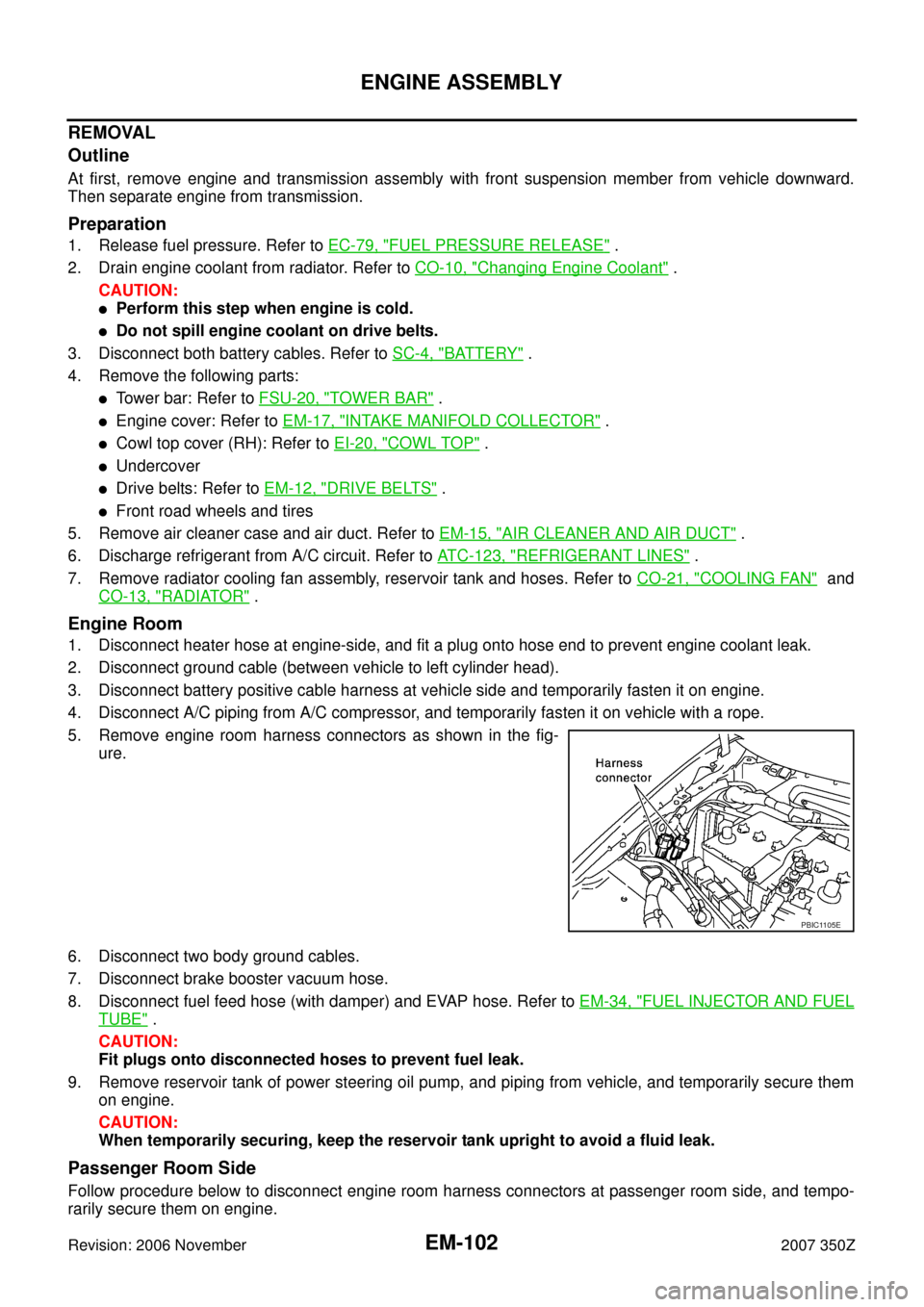
5. Remove engine room harness connectors as shown in the fig-
ure.
6. Disconnect two body ground cables.
7. Disconnect brake booster vacuum hose.
8. Disconnect fuel feed hose (with damper) and EVAP hose. Refer to EM-34, "
FUEL INJECTOR AND FUEL
TUBE" .
CAUTION:
Fit plugs onto disconnected hoses to prevent fuel leak.
9. Remove reservoir tank of power steering oil pump, and piping from vehicle, and temporarily secure them
on engine.
CAUTION:
When temporarily securing, keep the reservoir tank upright to avoid a fluid leak.
Passenger Room Side
Follow procedure below to disconnect engine room harness connectors at passenger room side, and tempo-
rarily secure them on engine.
PBIC1105E