Page 74 of 148

EM-74
CAMSHAFT
Revision: 2006 November2007 350Z
INSPECTION AFTER REMOVAL
Camshaft Runout
1. Put V-block on precise flat table, and support No. 2 and 4 jour-
nals of camshaft.
CAUTION:
Do not support journal No. 1 (on the side of camshaft
sprocket) because it has a different diameter from the other
three locations.
2. Set dial indicator vertically to No. 3 journal.
3. Turn camshaft to one direction with hands, and measure the
camshaft runout on a dial indicator. (Total indicator reading)
4. If it exceeds the limit, replace camshaft.
Camshaft Cam Height
1. Measure the camshaft cam height with a micrometer.
2. If wear is beyond the limit, replace camshaft.
Camshaft Journal Oil Clearance
CAMSHAFT JOURNAL DIAMETER
�Measure the outer diameter of camshaft journal with a microme-
ter.
CAMSHAFT BRACKET INNER DIAMETER
�Tighten camshaft bracket bolt with the specified torque. Refer to EM-77, "INSTALLATION" for the tighten-
ing procedure.
�Measure the inner diameter “A” of camshaft bracket with a bore
gauge.Standard : Less than 0.02 mm (0.0008 in)
Limit : 0.05 mm (0.0020 in)
PBIC0929E
Standard cam height:
Intake : 45.865 – 46.055 mm (1.8057 – 1.8132 in)
Exhaust : 45.875 – 46.065 mm (1.8061 – 1.8136 in)
Cam wear limit
: 0.2 mm (0.008 in)
EMQ0072D
Standard:
No. 1 : 25.935 - 25.955 mm (1.0211 - 1.0218 in)
No. 2, 3, 4 : 23.445 - 23.465 mm (0.9230 - 0.9238 in)
PBIC0040E
Standard:
No. 1 : 26.000 - 26.021 mm (1.0236 - 1.0244 in)
No. 2, 3, 4 : 23.500 - 23.521 mm (0.9252 - 0.9260 in)
PBIC1645E
Page 75 of 148
 = (Camshaft bracket inner diameter) – (Camshaft journal diameter)
�If it exc")
CAMSHAFT
EM-75
C
D
E
F
G
H
I
J
K
L
MA
EM
Revision: 2006 November2007 350Z
CAMSHAFT JOURNAL OIL CLEARANCE
�(Oil clearance) = (Camshaft bracket inner diameter) – (Camshaft journal diameter)
�If it exceeds the limit, replace either or both camshaft and cylinder head.
NOTE:
Camshaft brackets cannot be replaced as single parts, because there are machined together with cylinder
head. Replace whole cylinder head assembly.
Camshaft End Play
�Install a dial indicator in thrust direction on front end of camshaft.
Measure the end play of a dial indicator when camshaft is
moved forward/backward (in direction to axis).
�Measure the following parts if out of the limit.
–Dimension “A” for camshaft No. 1 journal
–Dimension “B” for cylinder head No. 1 journal bearing
�Refer to the standards above, and then replace camshaft and/or
cylinder head.
Camshaft Sprocket Runout
1. Put V-block on precise flat table, and support No. 2 and 4 journal of camshaft.
CAUTION:
Do not support journal No. 1 (on the side of camshaft sprocket) because it has a different diameter
from the other three locations.
2. Measure the camshaft sprocket runout with a dial indicator.
(Total indicator reading)
�If it exceeds the limit, replace camshaft sprocket.
CAUTION:
When replacing camshaft sprocket (EXH), replace valve
timing control cover (including magnet retarder and cover). Standard:
No. 1 : 0.045 - 0.086 mm (0.0018 - 0.0034 in)
No. 2, 3, 4 : 0.035 - 0.076 mm (0.0014 - 0.0030 in)
Limit : 0.15 mm (0.0059 in)
Standard : 0.115 - 0.188 mm (0.0045 - 0.0074 in)
Limit : 0.24 mm (0.0094 in)
SEM864E
Standard : 27.500 - 27.548 mm (1.0827 - 1.0846 in)
Standard : 27.360 - 27.385 mm (1.0772 - 1.0781 in)
KBIA2404J
Limit : 0.15 mm (0.0059 in)
PBIC0930E
Page 81 of 148

CAMSHAFT
EM-81
C
D
E
F
G
H
I
J
K
L
MA
EM
Revision: 2006 November2007 350Z
In cases of removing/installing or replacing camshaft and valve-
related parts, or of unusual engine conditions due to changes in
valve clearance (found malfunctions during stating, idling or causing
noise), perform inspection as follows:
1. Remove rocker covers (right and left bank). Refer to EM-40, "
ROCKER COVER" .
2. Measure the valve clearance as follows:
a. Set No. 1 cylinder at TDC of its compression stroke.
�Rotate crankshaft pulley clockwise to align timing mark
(grooved line without color) with timing indicator.
�Make sure that intake and exhaust cam nose on No. 1 cylin-
der (engine front side of right bank) are located as shown in
the figure.
�If not, turn crankshaft one revolution (360 degrees) and align
as shown in the figure.
b. Use a feeler gauge, measure the clearance between valve lifter
and camshaft.
Valve clearance:
Unit: mm (in)
*: Approximately 80°C (176°F)
SEM713A
: Timing mark (grooved line without color)
PBIC4966E
SEM418G
SEM139D
Items Cold Hot * (reference data)
Intake 0.26 - 0.34 (0.010 - 0.013) 0.304 - 0.416 (0.012 - 0.016)
Exhaust 0.29 - 0.37 (0.011 - 0.015) 0.308 - 0.432 (0.012 - 0.017)
Page 82 of 148
EM-82
CAMSHAFT
Revision: 2006 November2007 350Z
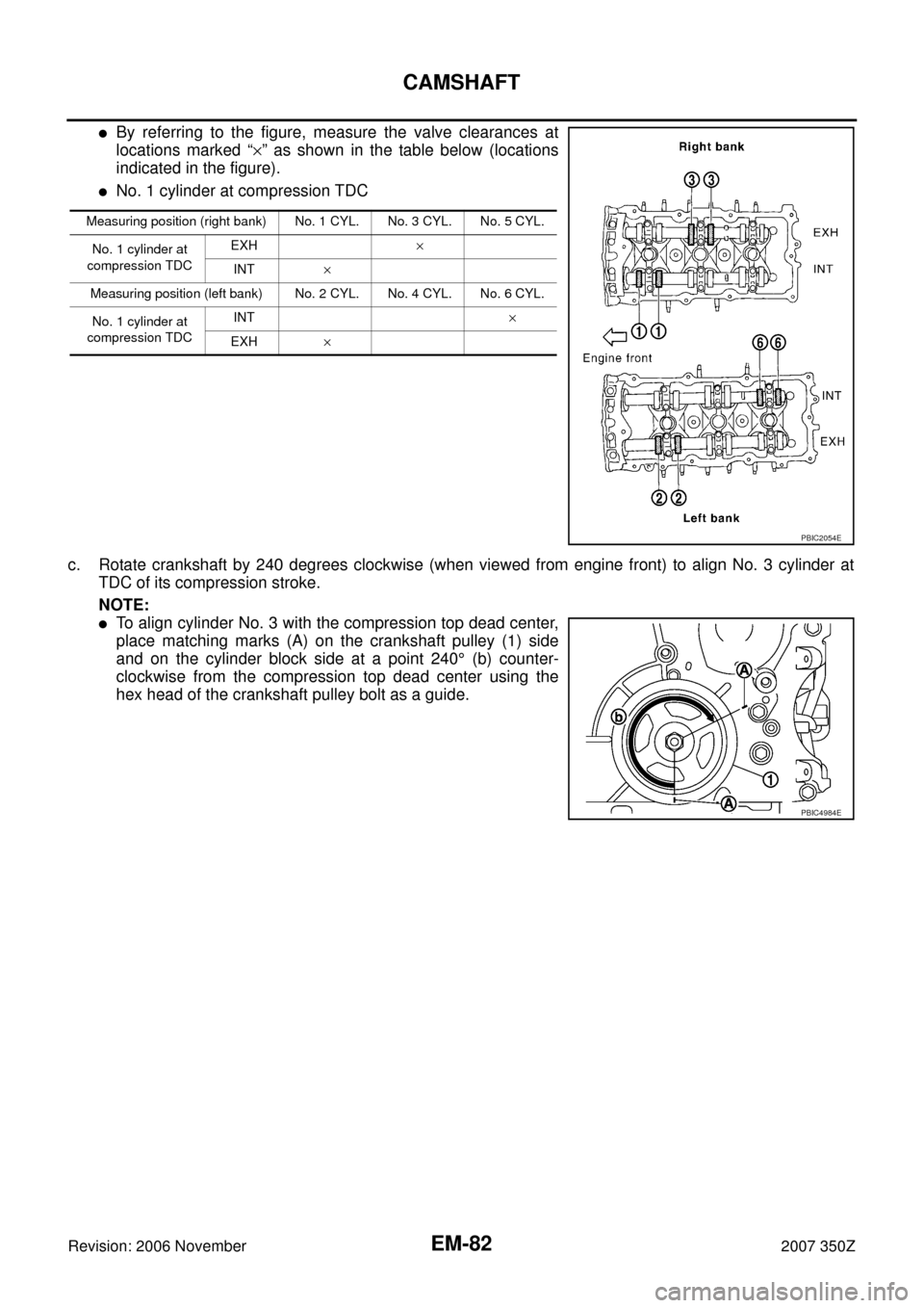
�By referring to the figure, measure the valve clearances at
locations marked “×” as shown in the table below (locations
indicated in the figure).
�No. 1 cylinder at compression TDC
c. Rotate crankshaft by 240 degrees clockwise (when viewed from engine front) to align No. 3 cylinder at
TDC of its compression stroke.
NOTE:
�To align cylinder No. 3 with the compression top dead center,
place matching marks (A) on the crankshaft pulley (1) side
and on the cylinder block side at a point 240° (b) counter-
clockwise from the compression top dead center using the
hex head of the crankshaft pulley bolt as a guide.
Measuring position (right bank) No. 1 CYL. No. 3 CYL. No. 5 CYL.
No. 1 cylinder at
compression TDCEXH×
INT×
Measuring position (left bank) No. 2 CYL. No. 4 CYL. No. 6 CYL.
No. 1 cylinder at
compression TDCINT×
EXH×
PBIC2054E
PBIC4984E
Page 83 of 148
CAMSHAFT
EM-83
C
D
E
F
G
H
I
J
K
L
MA
EM
Revision: 2006 November2007 350Z
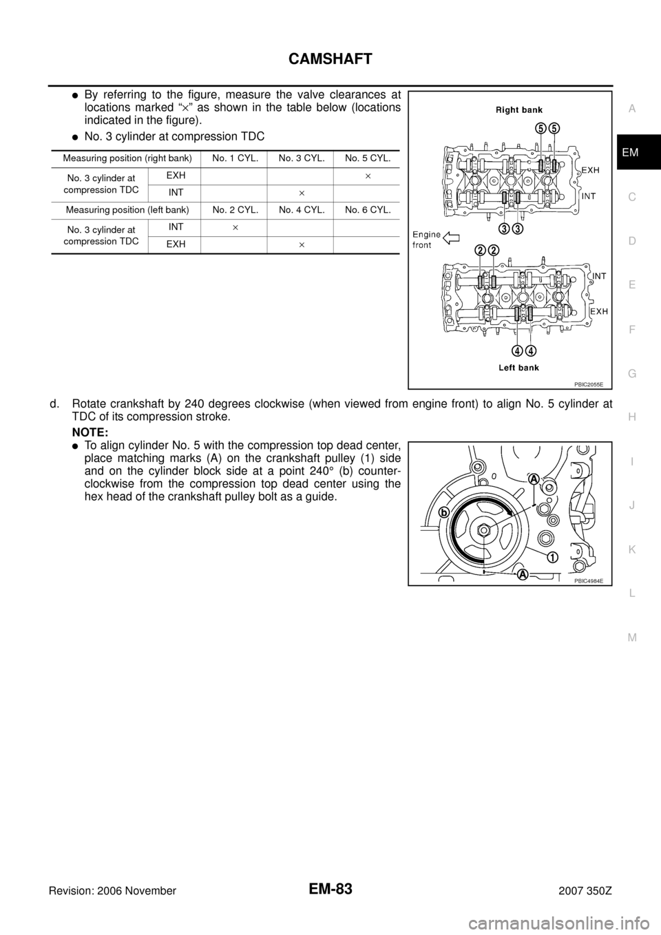
�By referring to the figure, measure the valve clearances at
locations marked “×” as shown in the table below (locations
indicated in the figure).
�No. 3 cylinder at compression TDC
d. Rotate crankshaft by 240 degrees clockwise (when viewed from engine front) to align No. 5 cylinder at
TDC of its compression stroke.
NOTE:
�To align cylinder No. 5 with the compression top dead center,
place matching marks (A) on the crankshaft pulley (1) side
and on the cylinder block side at a point 240° (b) counter-
clockwise from the compression top dead center using the
hex head of the crankshaft pulley bolt as a guide.
Measuring position (right bank) No. 1 CYL. No. 3 CYL. No. 5 CYL.
No. 3 cylinder at
compression TDCEXH×
INT×
Measuring position (left bank) No. 2 CYL. No. 4 CYL. No. 6 CYL.
No. 3 cylinder at
compression TDCINT×
EXH ×
PBIC2055E
PBIC4984E
Page 87 of 148

OIL SEAL
EM-87
C
D
E
F
G
H
I
J
K
L
MA
EM
Revision: 2006 November2007 350Z
Removal and Installation of Front Oil SealNBS0000W
REMOVAL
1. Remove the following parts:
�Undercover
�Drive belts: Refer to EM-12, "DRIVE BELTS" .
�Radiator cooling fan assembly: Refer to CO-21, "COOLING FAN" .
�Crankshaft pulley: Refer to EM-53, "TIMING CHAIN" .
2. Remove front oil seal using suitable tool.
CAUTION:
Be careful not to damage front timing chain case and crank-
shaft.
INSTALLATION
1. Apply engine oil to both oil seal lip and dust seal lip of new front oil seal.
2. Install front oil seal.
�Install front oil seal so that each seal lip is oriented as shown
in the figure.
�Using suitable drift, press-fit until the height of front oil seal is
level with the mounting surface.
–Suitable drift: outer diameter 60 mm (2.36 in), inner diameter
50 mm (1.97 in).
CAUTION:
�Be careful not to damage front timing chain case and
crankshaft.
�Press-fit straight and avoid causing burrs or tilting oil
seal.
3. Install in the reverse order of removal after this step.
Removal and Installation of Rear Oil SealNBS0000X
REMOVAL
1. Remove transmission assembly. Refer to MT-18, "TRANSMISSION ASSEMBLY" (M/T models) or AT-
242, "TRANSMISSION ASSEMBLY" (A/T models).
2. Remove clutch cover and clutch disk (M/T models). Refer to CL-16, "
CLUTCH DISC, CLUTCH COVER" .
3. Remove flywheel (M/T models) or drive plate (A/T models). Refer to EM-107, "
CYLINDER BLOCK" .
PBIC2931E
SEM715A
PBIC2931E
Page 88 of 148
EM-88
OIL SEAL
Revision: 2006 November2007 350Z
4. Remove rear oil seal with a suitable tool.
CAUTION:
Be careful not to damage crankshaft and cylinder block.
INSTALLATION
1. Apply new engine oil to new rear oil seal joint surface and seal lip.
2. Install rear oil seal so that each seal lip is oriented as shown.
�Press in rear oil seal to the position as shown.
�Using suitable drift, press-fit until the height of front oil seal is
level with the mounting surface.
–Suitable drift: outer diameter 100 mm (3.94 in), inner diameter
85 mm (3.35 in).
CAUTION:
�Be careful not to damage crankshaft and cylinder block.
�Press-fit oil seal straight to avoid causing burrs or tilting.
3. Install in the reverse order of removal after this step.
PBIC2932E
SEM715A
SBIA0281E
LBIA0454E
Page 91 of 148

CYLINDER HEAD
EM-91
C
D
E
F
G
H
I
J
K
L
MA
EM
Revision: 2006 November2007 350Z
�Fuel tube and fuel injector assembly: Refer to EM-34, "FUEL INJECTOR AND FUEL TUBE" .
�Intake manifold: Refer to EM-20, "INTAKE MANIFOLD" .
�Exhaust manifold: Refer to EM-22, "EXHAUST MANIFOLD AND THREE WAY CATALYST" .
�Water inlet and thermostat assembly: Refer to CO-26, "WATER INLET AND THERMOSTAT ASSEM-
BLY" .
�Water outlet and water pipe: Refer to CO-28, "WATER OUTLET AND WATER PIPING" .
�Front and rear timing chain case: Refer to EM-53, "TIMING CHAIN" .
3. Remove camshaft (INT, EXH). Refer to EM-72, "
CAMSHAFT" .
4. Remove cylinder head bolts in reverse order as shown in the fig-
ure with cylinder head bolt wrench (commercial service tool).
5. Remove cylinder head gaskets.
INSPECTION AFTER REMOVAL
Cylinder Head Bolts Outer Diameter
�Cylinder head bolts are tightened by plastic zone tightening
method. Whenever the size difference between “d1” and “d2”
exceeds the limit, replace them with new one.
�If reduction of outer diameter appears in a position other than
“d2”, use it as “d2” point.
Cylinder Head Distortion
NOTE:
When performing this inspection, cylinder block distortion should be also checked. Refer to EM-128, "
CYLIN-
DER BLOCK DISTORTION" .
1. Using scraper, wipe off oil, scale, gasket, sealant and carbon deposits from surface of cylinder head.
CAUTION:
Do not allow gasket fragments to enter engine oil or engine coolant passages.
PBIC2057E
Limit (“d1” – “d2”) : 0.18 mm (0.0071 in)
PBIC2480E