Page 93 of 148
.
CAUTION:
Check the tightening angle by using angle wrench (SST")
CYLINDER HEAD
EM-93
C
D
E
F
G
H
I
J
K
L
MA
EM
Revision: 2006 November2007 350Z
e. Turn all bolts 95 degrees clockwise (angle tightening).
CAUTION:
Check the tightening angle by using angle wrench (SST).
Avoid judgment by visual inspection without tool.
�Check tightening angle indicated on angle wrench (SST) indi-
cator plate.
f. Turn all bolts 95 degrees clockwise again (angle tightening).
4. After installing cylinder head, measure distance between front
end faces of cylinder block and cylinder head (left and right
banks).
�If the measured value is out of the standard, re-install cylinder
head.
5. Install in the reverse order of removal after this step.
INSPECTION AFTER INSTALLATION
Inspection for Leaks
The following are procedures for checking fluids leak, lubricates leak and exhaust gases leak.
�Before starting engine, check oil/fluid levels including engine coolant and engine oil. If less than required
quantity, fill to the specified level. Refer to MA-11, "
RECOMMENDED FLUIDS AND LUBRICANTS" .
�Use procedure below to check for fuel leakage.
–Turn ignition switch “ON” (with engine stopped). With fuel pressure applied to fuel piping, check for fuel
leakage at connection points.
–Start engine. With engine speed increased, check again for fuel leakage at connection points.
�Run engine to check for unusual noise and vibration.
�Warm up engine thoroughly to make sure there is no leakage of fuel, exhaust gases, or any oil/fluids
including engine oil and engine coolant.
�Bleed air from lines and hoses of applicable lines, such as in cooling system.
�After cooling down engine, again check oil/fluid levels including engine oil and engine coolant. Refill to the
specified level, if necessary.
Summary of the inspection items:
* Transmission/transaxle/CVT fluid, power steering fluid, brake fluid, etc.
PBIC0888E
Standard : 14.1 - 14.9 mm (0.555 - 0.587 in)
EMQ0662D
Items Before starting engine Engine running After engine stopped
Engine coolant Level Leakage Level
Engine oil Level Leakage Level
Other oils and fluid* Level Leakage Level
Fuel Leakage Leakage Leakage
Exhaust gases — Leakage —
Page 96 of 148
. Install valve collet with magnet
hand")
EM-96
CYLINDER HEAD
Revision: 2006 November2007 350Z
8. Install valve collet.
�Compress valve spring with valve spring compressor, attach-
ment and adapter (SST). Install valve collet with magnet
hand.
CAUTION:
When working, take care not to damage valve lifter holes.
�Tap valve stem edge lightly with plastic hammer after installa-
tion to check its installed condition.
9. Install valve lifter.
�Install it in the original position.
10. Install spark plug tube.
�Press-fit spark plug tube as follows:
a. Remove old liquid gasket adhering to cylinder head mounting hole.
b. Apply liquid gasket to area within approximately 12 mm (0.47 in) from edge of spark plug tube press-fit
side.
Use Genuine High Strength Locking Sealant or equivalent. Refer to GI-45, "
RECOMMENDED
CHEMICAL PRODUCTS AND SEALANTS" .
c. Using drift, press-fit spark plug tube so that its height “H” is as
specified in the figure.
CAUTION:
�When press-fitting, take care not to deform spark plug
tube.
�After press-fitting, wipe off liquid gasket protruding onto
cylinder-head upper face.
11. Install spark plug with spark plug wrench (commercial service
tool).
Inspection After DisassemblyNBS00011
VALVE DIMENSIONS
�Check dimensions of each valve. For dimensions, refer to EM-
139, "Valve Dimensions" .
�If dimensions are out of the standard, replace valve and check
valve seat contact. Refer to EM-99, "
VALVE SEAT CONTACT" .
PBIC1803E
Standard press-fit height “H”:
: 37.7 - 38.7 mm (1.484 - 1.524 in)
PBIC2638E
SEM188A
Page 105 of 148
ENGINE ASSEMBLY
EM-105
C
D
E
F
G
H
I
J
K
L
MA
EM
Revision: 2006 November2007 350Z
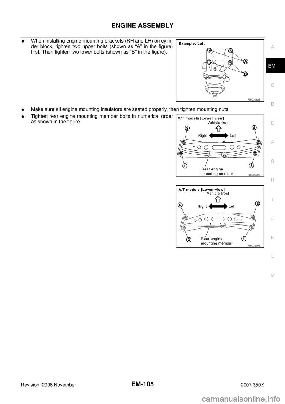
�When installing engine mounting brackets (RH and LH) on cylin-
der block, tighten two upper bolts (shown as “A” in the figure)
first. Then tighten two lower bolts (shown as “B” in the figure).
�Make sure all engine mounting insulators are seated properly, then tighten mounting nuts.
�Tighten rear engine mounting member bolts in numerical order
as shown in the figure.
PBIC2062E
PBIC2289E
PBIC2290E
Page 107 of 148
CYLINDER BLOCK
EM-107
C
D
E
F
G
H
I
J
K
L
MA
EM
Revision: 2006 November2007 350Z
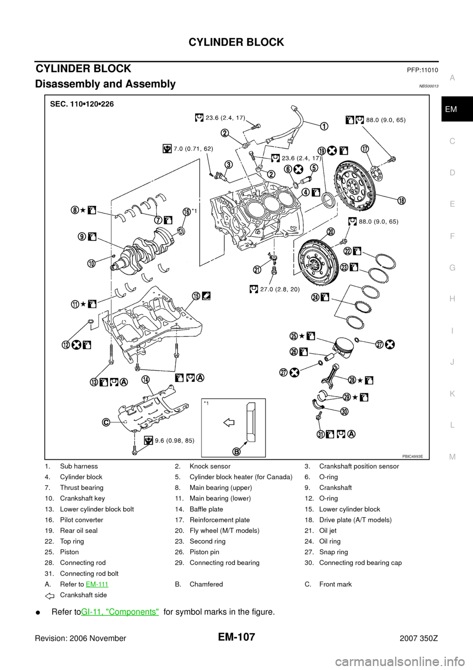
CYLINDER BLOCKPFP:11010
Disassembly and AssemblyNBS00013
�Refer toGI-11, "Components" for symbol marks in the figure.
1. Sub harness 2. Knock sensor 3. Crankshaft position sensor
4. Cylinder block 5. Cylinder block heater (for Canada) 6. O-ring
7. Thrust bearing 8. Main bearing (upper) 9. Crankshaft
10. Crankshaft key 11. Main bearing (lower) 12. O-ring
13. Lower cylinder block bolt 14. Baffle plate 15. Lower cylinder block
16. Pilot converter 17. Reinforcement plate 18. Drive plate (A/T models)
19. Rear oil seal 20. Fly wheel (M/T models) 21. Oil jet
22. Top ring 23. Second ring 24. Oil ring
25. Piston 26. Piston pin 27. Snap ring
28. Connecting rod 29. Connecting rod bearing 30. Connecting rod bearing cap
31. Connecting rod bolt
A. Refer to E M - 111
B. Chamfered C. Front mark
Crankshaft side
PBIC4993E
Page 108 of 148

EM-108
CYLINDER BLOCK
Revision: 2006 November2007 350Z
DISASSEMBLY
1. Remove engine assembly from vehicle, and separate front suspension member and transmission from
engine. Refer to EM-101, "
ENGINE ASSEMBLY" .
2. Remove engine mounting brackets (RH and LH). Refer to EM-101, "
ENGINE ASSEMBLY" .
3. Remove the parts that may restrict installation of engine to widely use engine stand.
NOTE:
The procedure is described assuming that you use a widely use engine stand holding the surface, to
which transmission is installed.
�Remove clutch cover and clutch disk (M/T models). Refer to CL-16, "CLUTCH DISC, CLUTCH
COVER" .
�Remove flywheel (M/T models) or drive plate (A/T models). Fix crankshaft with a ring gear stopper
[SST: KV10118600 (J-48641)], and remove mounting bolts.
�Loosen mounting bolts in diagonal order.
�Check for deformation or damage (A).
CAUTION:
�Do not disassemble drive plate.
�Never place drive plate with signal plate facing down.
�When handling signal plate, take care not to damage or
scratch it.
�Handle signal plate in a manner that prevents it from
becoming magnetized.
4. Remove pilot bushing (M/T models) or pilot converter (A/T mod-
els) using pilot bushing puller [SST: ST16610001 (J-23907)] (A)
or suitable tool as necessary.
5. Lift the engine with hoist to install it onto the widely use engine stand.
�A widely use engine stand can be used.
CAUTION:
Use engine stand that has a load capacity [approximately
220 kg (485 lb) or more] large enough for supporting the
engine weight.
NOTE:
This example is engine stand for holding at transmission
mounting side with flywheel (M/T models) or drive plate (A/T
models) removed.
6. Drain engine oil. Refer to LU-7, "
Changing Engine Oil" .
SEM760G
PBIC5015E
PBIC0085E
Page 109 of 148
 from
cylinder block both sides as shown in the figure.
8.")
CYLINDER BLOCK
EM-109
C
D
E
F
G
H
I
J
K
L
MA
EM
Revision: 2006 November2007 350Z
7. Drain engine coolant by removing water drain plugs (1, 4) from
cylinder block both sides as shown in the figure.
8. Remove oil pan (upper, lower). Refer to EM-26, "
OIL PAN AND OIL STRAINER" .
9. Remove front timing chain case, timing chain and rear timing chain case. Refer to EM-53, "
TIMING
CHAIN" .
10. Remove cylinder head. Refer to EM-89, "
CYLINDER HEAD" .
11. Remove knock sensor.
CAUTION:
Carefully handle sensor avoiding shocks.
12. Remove rear oil seal.
13. Remove baffle plate from lower cylinder block.
14. Remove piston and connecting rod assembly as follows:
�Before removing piston and connecting rod assembly, check the connecting rod side clearance. Refer
to EM-125, "
CONNECTING ROD SIDE CLEARANCE" .
a. Position crankshaft pin corresponding to connecting rod to be removed onto the bottom dead center.
b. Remove connecting rod bearing cap.
c. Using hammer handle or similar tool, push piston and connect-
ing rod assembly out to the cylinder head side.
CAUTION:
Be careful not to damage the cylinder wall and crankshaft
pin, resulting from an interference of the connecting rod big
end.
15. Remove connecting rod bearings from connecting rod and connecting rod bearing cap.
CAUTION:
Identify installation position, and store them without mixing them up.
16. Remove piston rings form piston.
�Before removing piston rings, check the piston ring side clearance. Refer to EM-126, "PISTON RING
SIDE CLEARANCE" .
2 : Washer
3: Plug
: Engine front
PBIC5014E
PBIC2940E
Page 110 of 148
EM-110
CYLINDER BLOCK
Revision: 2006 November2007 350Z
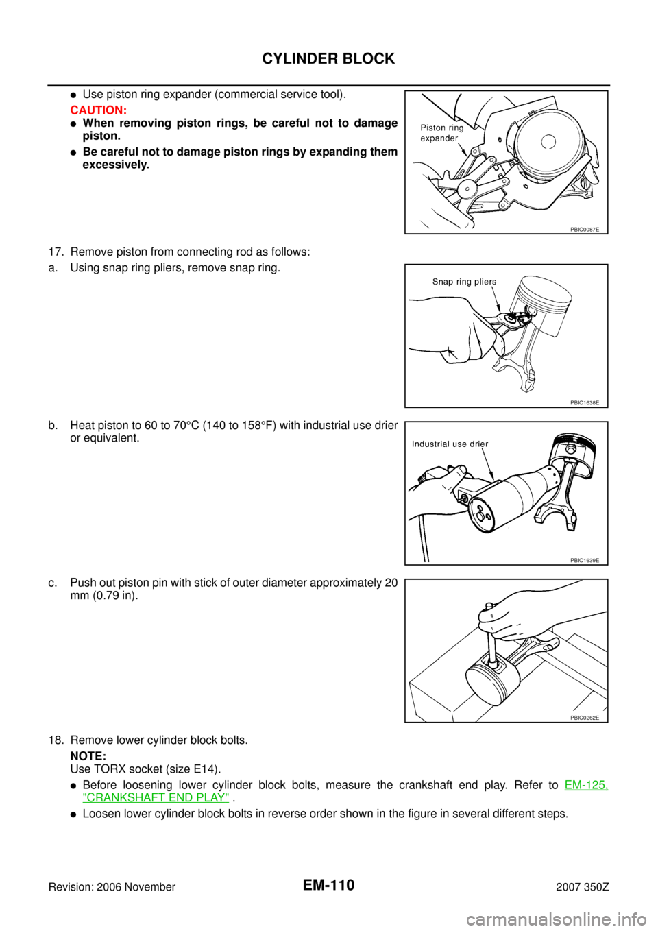
�Use piston ring expander (commercial service tool).
CAUTION:
�When removing piston rings, be careful not to damage
piston.
�Be careful not to damage piston rings by expanding them
excessively.
17. Remove piston from connecting rod as follows:
a. Using snap ring pliers, remove snap ring.
b. Heat piston to 60 to 70°C (140 to 158°F) with industrial use drier
or equivalent.
c. Push out piston pin with stick of outer diameter approximately 20
mm (0.79 in).
18. Remove lower cylinder block bolts.
NOTE:
Use TORX socket (size E14).
�Before loosening lower cylinder block bolts, measure the crankshaft end play. Refer to EM-125,
"CRANKSHAFT END PLAY" .
�Loosen lower cylinder block bolts in reverse order shown in the figure in several different steps.
PBIC0087E
PBIC1638E
PBIC1639E
PBIC0262E
Page 111 of 148
![NISSAN 350Z 2007 Z33 Engine Mechanical Workshop Manual CYLINDER BLOCK
EM-111
C
D
E
F
G
H
I
J
K
L
MA
EM
Revision: 2006 November2007 350Z
19. Remove lower cylinder block as follows:
Screw M8 bolt [Pitch: 1.25 mm (0.049 in), Length: approx. 50
mm (1.97 in)]](/manual-img/5/765/w960_765-110.png "NISSAN 350Z 2007 Z33 Engine Mechanical Workshop Manual CYLINDER BLOCK
EM-111
C
D
E
F
G
H
I
J
K
L
MA
EM
Revision: 2006 November2007 350Z
19. Remove lower cylinder block as follows:
Screw M8 bolt [Pitch: 1.25 mm (0.049 in), Length: approx. 50
mm (1.97 in)]")
CYLINDER BLOCK
EM-111
C
D
E
F
G
H
I
J
K
L
MA
EM
Revision: 2006 November2007 350Z
19. Remove lower cylinder block as follows:
Screw M8 bolt [Pitch: 1.25 mm (0.049 in), Length: approx. 50
mm (1.97 in)] into bolt holes (A) shown in the figure. Then
equally tighten each bolt, and remove lower cylinder block.
CAUTION:
�Be careful not to damage the mating surface.
�Do not tighten bolts too much.
�Do not insert screw driver, this will damage the mating
surface.
20. Remove crankshaft.
21. Pull rear oil seal out from rear end of crankshaft.
22. Remove main bearings and thrust bearings from cylinder block and lower cylinder block.
CAUTION:
�Identify installation positions, and store them without mixing them up.
�Be careful not to drop main bearing, and to scratch the surface.
23. Remove oil jet.
ASSEMBLY
1. Fully air-blow engine coolant and engine oil passages in cylinder block, cylinder bore and crankcase to
remove any foreign material.
CAUTION:
Use a goggles to protect your eye.
: Engine front
PBIC5016E
: Engine front
PBIC5047E