Page 17 of 54

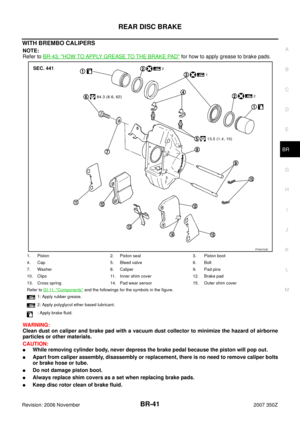
BRAKE MASTER CYLINDER
BR-17
C
D
E
G
H
I
J
K
L
MA
B
BR
Revision: 2006 November2007 350Z
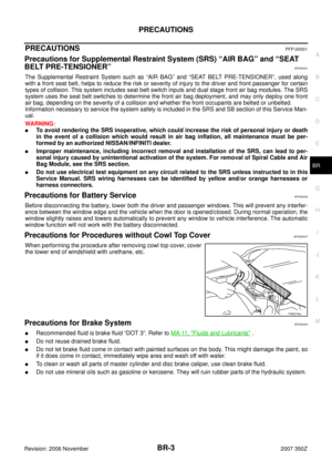
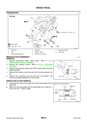
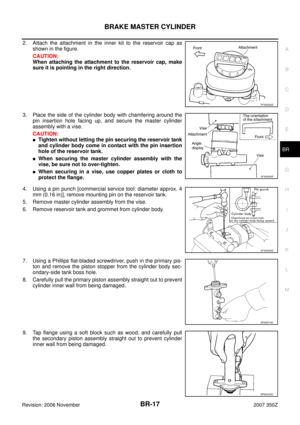
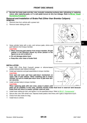
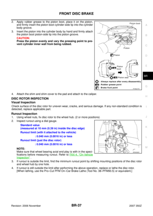
2. Attach the attachment in the inner kit to the reservoir cap as
shown in the figure.
CAUTION:
When attaching the attachment to the reservoir cap, make
sure it is pointing in the right direction.
3. Place the side of the cylinder body with chamfering around the
pin insertion hole facing up, and secure the master cylinder
assembly with a vise.
CAUTION:
�Tighten without letting the pin securing the reservoir tank
and cylinder body come in contact with the pin insertion
hole of the reservoir tank.
�When securing the master cylinder assembly with the
vise, be sure not to over-tighten.
�When securing in a vise, use copper plates or cloth to
protect the flange.
4. Using a pin punch [commercial service tool: diameter approx. 4
mm (0.16 in)], remove mounting pin on the reservoir tank.
5. Remove master cylinder assembly from the vise.
6. Remove reservoir tank and grommet from cylinder body.
7. Using a Phillips flat-bladed screwdriver, push in the primary pis-
ton and remove the piston stopper from the cylinder body sec-
ondary-side tank boss hole.
8. Carefully pull the primary piston assembly straight out to prevent
cylinder inner wall from being damaged.
9. Tap flange using a soft block such as wood, and carefully pull
the secondary piston assembly straight out to prevent cylinder
inner wall from being damaged.
PFIA0262E
SFIA0699E
SFIA0250E
BRA0519D
BRA0033D
Page 18 of 54

BR-18
BRAKE MASTER CYLINDER
Revision: 2006 November2007 350Z
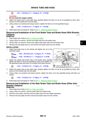
Inspection after Disassembly
Master cylinder
�Check that there is no damage, friction, rusting, or pinholes on the cylinder inner wall, and replace if there
are any non-standard conditions.
Assembly
CAUTION:
�Do not use mineral oils such as kerosene, gasoline during the cleaning and assembly process.
�Make sure there is no foreign matter such as dirt or dust attached to the inner cylinder walls, the
piston, or the cap seal, and use care to avoid damaging parts with the assembly tools.
�Do not drop parts. If a part is dropped, do not use it.
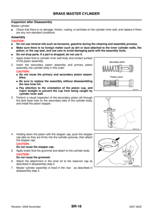
1. Apply brake fluid to cylinder inner wall body and contact surface
of the piston assembly.
2. Insert the secondary piston assembly and primary piston
assembly into cylinder body in this order.
CAUTION:
�Do not reuse the primary and secondary piston assem-
blies.
�Be sure to replace the assembly without disassembling
the new inner kit.
�Pay attention to the orientation of the piston cup, and
insert straight to prevent the cup from being caught by
cylinder inner wall.
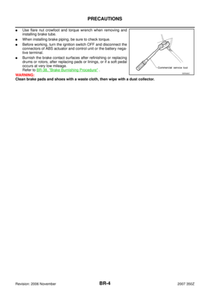
3. Perform a visual inspection of the secondary piston slit through
the tank boss hole on the secondary-side of the cylinder body,
and install the piston stopper.
4. Holding down the piston with the stopper cap, push the stopper
cap tabs so they are firmly into the cylinder grooves, then attach
the stopper cap.
CAUTION:
Do not reuse the stopper cap.
5. Apply brake fluid the grommet and attach to the cylinder body.
CAUTION:
Do not reuse the grommet.
6. Attach the attachment in the inner kit to the reservoir cap as
described in disassembly step 2.
7. Master cylinder assembly is fixed in the vise as described in
disassembly step 3.SBR089C
BRA0519D
BRA0035D
Page 19 of 54

BRAKE MASTER CYLINDER
BR-19
C
D
E
G
H
I
J
K
L
MA
B
BR
Revision: 2006 November2007 350Z
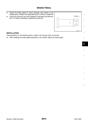
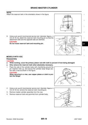
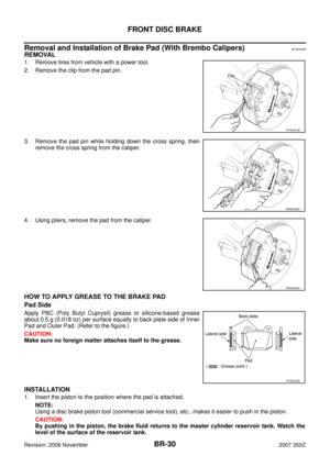
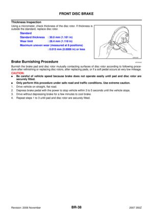
NOTE:
Attach the reservoir tank in the orientation shown in the figure.
8. Using a pin punch [commercial service tool: diameter Approx. 4
mm (0.16 in)], attach the reservoir tank mounting pin so that the
attachment side and the opposite side are identical.
CAUTION:
Do not reuse reservoir tank and mounting pin.
MODELS WITH VDC
Disassembly
CAUTION:
�While working, cover the primary piston rod with cloth to prevent it from being damaged.
�Only remove the reservoir tank when absolutely necessary.
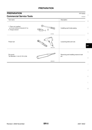
1. Place the side of the cylinder body with chamfering around the
pin insertion hole up, and secure the cylinder body flange sec-
tion with a vise as shown in the figure.
CAUTION:
When securing in a vise, use copper plates or cloth to pro-
tect the flange.
2. Using a pin punch [commercial service tool: diameter Approx 4
mm (0.16 in)], remove the reservoir tank mounting pin.
3. Remove master cylinder assembly from the vise.
4. Remove reservoir tank and grommet from cylinder body.
BRA0568D
SFIA0250E
BRA0558D
BRA0559D
Page 20 of 54

BR-20
BRAKE MASTER CYLINDER
Revision: 2006 November2007 350Z
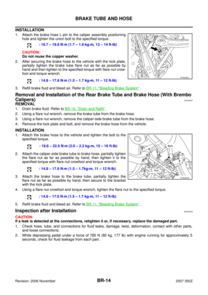
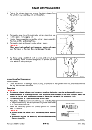
5. Push in the primary piston and remove the piston stopper from
the cylinder body secondary-side tank boss hole.
6. Remove the snap ring while pushing the primary piston in to pre-
vent the piston from popping out.
7. Holding the primary piston rod, pull the primary piston assembly,
the plate, and the guide straight out.
8. Remove the plate and guide from the primary piston.
CAUTION:
When removing the plate from the primary piston rod, make
sure the inside of the plate does not damage the rod.
9. Tap flange using a soft block such as wood, and carefully pull
the secondary piston assembly straight out to prevent cylinder
inner wall from being damaged.
Inspection after Disassembly
Master cylinder
�Check that there is no damage, friction, rusting, or pinholes on the cylinder inner wall, and replace if there
are any non-standard conditions.
Assembly
CAUTION:
�Do not use mineral oils such as kerosene, gasoline during the cleaning and assembly process.
�Make sure there is no foreign matter such as dirt or dust attached to the inner cylinder walls, the
piston, or the cap seal, and use care to avoid damaging parts with the assembly tools.
�Do not drop parts. If a part is dropped, do not use it.
1. Apply brake fluid to cylinder inner wall body and contact surface
of the piston assembly, and apply the silicon grease in the inner
kit to the primary piston rod.
2. Insert the secondary piston and primary piston into cylinder
body in this order.
CAUTION:
�Do not reuse the primary and secondary piston assem-
blies.
�Be sure to replace the assembly without disassembling
the new inner kit.
BRA0560D
BRA0561D
BRA0033D
PFIA0263E
Page 21 of 54

BRAKE MASTER CYLINDER
BR-21
C
D
E
G
H
I
J
K
L
MA
B
BR
Revision: 2006 November2007 350Z
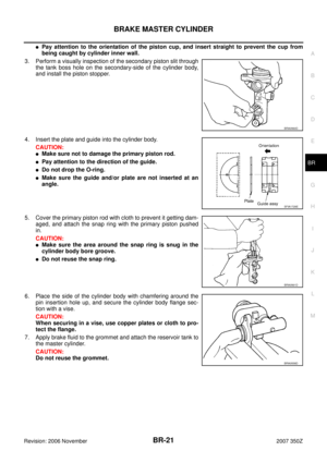
�Pay attention to the orientation of the piston cup, and insert straight to prevent the cup from
being caught by cylinder inner wall.
3. Perform a visually inspection of the secondary piston slit through
the tank boss hole on the secondary-side of the cylinder body,
and install the piston stopper.
4. Insert the plate and guide into the cylinder body.
CAUTION:
�Make sure not to damage the primary piston rod.
�Pay attention to the direction of the guide.
�Do not drop the O-ring.
�Make sure the guide and/or plate are not inserted at an
angle.
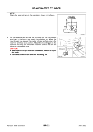
5. Cover the primary piston rod with cloth to prevent it getting dam-
aged, and attach the snap ring with the primary piston pushed
in.
CAUTION:
�Make sure the area around the snap ring is snug in the
cylinder body bore groove.
�Do not reuse the snap ring.
6. Place the side of the cylinder body with chamfering around the
pin insertion hole up, and secure the cylinder body flange sec-
tion with a vise.
CAUTION:
When securing in a vise, use copper plates or cloth to pro-
tect the flange.
7. Apply brake fluid to the grommet and attach the reservoir tank to
the master cylinder.
CAUTION:
Do not reuse the grommet.
BRA0560D
SFIA1729E
BRA0561D
BRA0558D
Page 22 of 54
BR-22
BRAKE MASTER CYLINDER
Revision: 2006 November2007 350Z
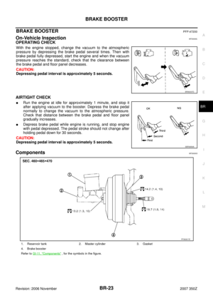
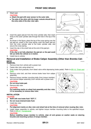
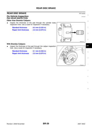
NOTE:
Attach the reservoir tank in the orientation shown in the figure.
8. Tilt the reservoir tank so that the mounting pin can be inserted
as shown in the figure, and insert the mounting pin. When the
mounting pin has passed the master cylinder pinhole, return the
reservoir tank to a level position. Attach the mounting pin to the
opposite mounting pin hole of the reservoir tank so that it is the
same as the insertion side.
CAUTION:
�Be sure to insert pin from the chamfered pinhole of cylin-
der body.
�Do not reuse reservoir tank and mounting pin.
BRA0568D
SFIA0702E
Page 23 of 54

BRAKE BOOSTER
BR-23
C
D
E
G
H
I
J
K
L
MA
B
BR
Revision: 2006 November2007 350Z
BRAKE BOOSTERPFP:47200
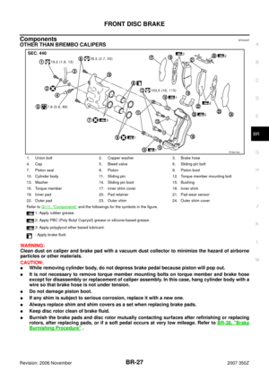
On-Vehicle InspectionNFS0000L
OPERATING CHECK
With the engine stopped, change the vacuum to the atmospheric
pressure by depressing the brake pedal several times. Then with
brake pedal fully depressed, start the engine and when the vacuum
pressure reaches the standard, check that the clearance between
the brake pedal and floor panel decreases.
CAUTION:
Depressing pedal interval is approximately 5 seconds.
AIRTIGHT CHECK
�Run the engine at idle for approximately 1 minute, and stop it
after applying vacuum to the booster. Depress the brake pedal
normally to change the vacuum to the atmospheric pressure.
Check that distance between the brake pedal and floor panel
gradually increases.
�Depress brake pedal while engine is running, and stop engine
with pedal depressed. The pedal stroke should not change after
holding pedal down for 30 seconds.
CAUTION:
Depressing pedal interval is approximately 5 seconds.
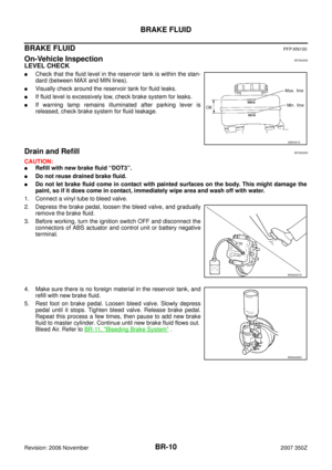
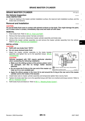
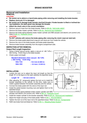
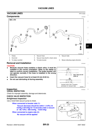
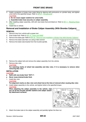
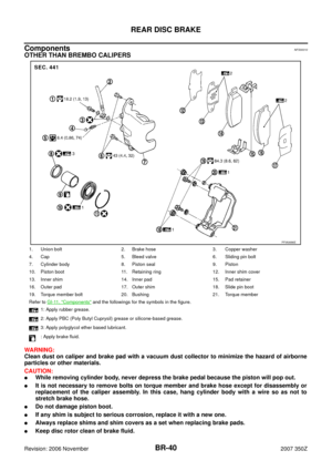
ComponentsNFS000IG
BRA0037D
SBR365AA
1. Reservoir tank 2. Master cylinder 3. Gasket
4. Brake booster
Refer to GI-11, "
Components" , for the symbols in the figure.
PFIA0817E
Page 24 of 54

BR-24
BRAKE BOOSTER
Revision: 2006 November2007 350Z
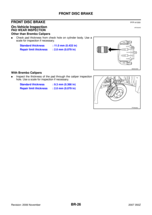
Removal and InstallationNFS0000M
REMOVAL
CAUTION:
�Be careful not to deform or bend brake piping while removing and installing the brake booster.
�Replace clevis pin if it is damaged.
�Be careful not to damage brake booster stud bolt threads. If brake booster is tilted or inclined dur-
ing installation, the dash panel may damage the threads.
�Attach the check valve in the correct orientation.
1. Remove vacuum hose from the brake booster. Refer to BR-25, "
VACUUM LINES" .
2. Remove the brake master cylinder. Refer to BR-24, "
Removal and Installation" .
3. Remove the brake piping between brake master cylinder and ABS actuator and electric unit (control unit).
Refer to BR-12, "
Hydraulic Circuit" .
CAUTION:
For M/T vehicles with remove the brake piping after removing the clutch reservoir tank bolt.
4. Remove the brake pedal attachment snap pin and clevis pin from inside the vehicle.
5. Remove the nuts on the brake booster and brake pedal assembly.
6. Remove brake booster assembly from the engine compartment side.
INSPECTION AFTER REMOVAL
Output Rod Length Inspection
1. Using a handy vacuum pump, apply a vacuum of −66.7 kPa (−
500 mmHg,−19.69 inHg) to the brake booster.
2. Check output rod length.
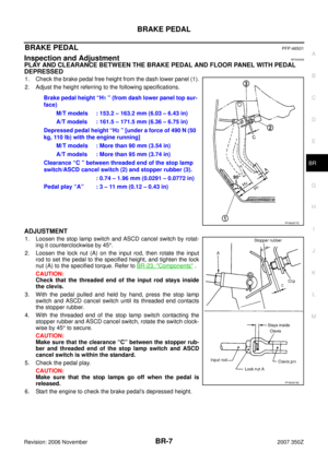
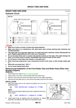
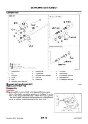
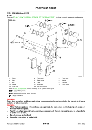
INSTALLATION
1. Loosen the lock nut to adjust the input rod length so that the
length “B” (in the figure on the right) satisfies the specified value.
2. After adjusting “B”, temporarily tighten the lock nut to install the
booster assembly to the vehicle. At this time, make sure to
install a gasket between the booster assembly and the vehicle.
3. Connect the brake pedal with the clevis of the input rod.
4. Install the pedal bracket mounting nuts and tighten them to the
specified torque.
5. Install the brake piping between brake master cylinder and ABS
actuator and electric unit (control unit). Refer to BR-12, "
Hydraulic Circuit" .
6. Install the master cylinder to the booster assembly. Refer to BR-24, "
Removal and Installation" .
7. Adjust the height and play of the brake pedal. Refer to BR-7, "
ADJUSTMENT" .
8. Tighten the lock nut of the input rod to the specified torque. Refer to BR-23, "
Components" .
9. Refill new brake fluid and bleed air. Refer to BR-11, "
Bleeding Brake System" . Standard dimension when vacuum −66.7 kPa
(−500 mmHg, −19.69 inHg)
With TCS : 10.4 mm (0.409 in)
With VDC : −6.2 mm (−0.244 in)
SBR208E
Length “B” : 125 mm (4.92 in)
SGIA0060E