Page 25 of 54

VACUUM LINES
BR-25
C
D
E
G
H
I
J
K
L
MA
B
BR
Revision: 2006 November2007 350Z
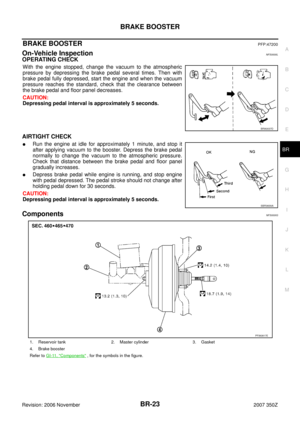
VACUUM LINESPFP:41920
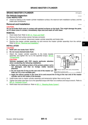
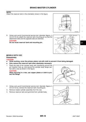
ComponentsNFS000IH
Removal and InstallationNFS0000N
CAUTION:
�Because vacuum hose contains a check valve, it must be
installed in the correct orientation. Refer to the stamp or
label to confirm correct installation. The brake booster will
not operate normally if the hose is installed in the wrong
direction.
�Insert the vacuum hose for at least 24 mm (0.94 in).
�Do not use lubricating oil during assembly.
InspectionNFS0000O
VISUAL INSPECTION
Check for improper assembly, damage and deteriorate.
CHECK VALVE INSPECTION
Airtightness Inspection
Use a hand-held vacuum pump to check.
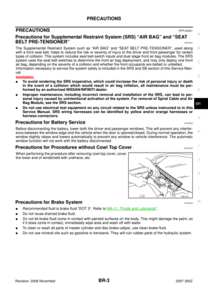
1. Clamp 2. Vacuum hose 3. Vacuum tube
4. Grommet 5. Vacuum hose (built in check valve)
A. To intake manifold B. To brake booster C. Stamp indicating engine direction
PFIA0893E
SBR225B
When connected to booster side (1):
Vacuum decrease should be within 1.3 kPa (10
mmHg, 0.39 inHg) for 15 seconds under a vacuum
of −66.7 kPa (−500 mmHg, −19.69 inHg)
When connected to engine side (2):
No vacuum will be applied
SFIA0210E
Page 26 of 54
BR-26
FRONT DISC BRAKE
Revision: 2006 November2007 350Z
FRONT DISC BRAKEPFP:41000
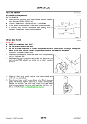
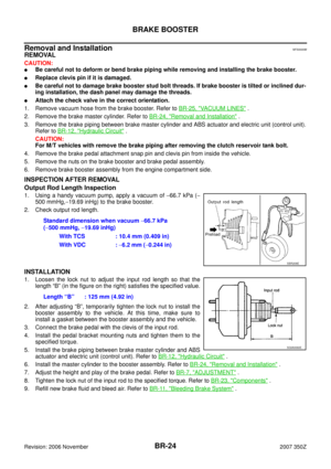
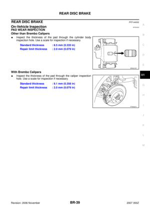
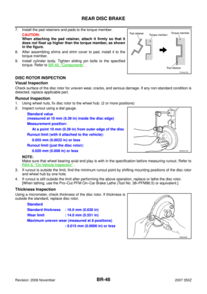
On-Vehicle InspectionNFS000AS
PAD WEAR INSPECTION
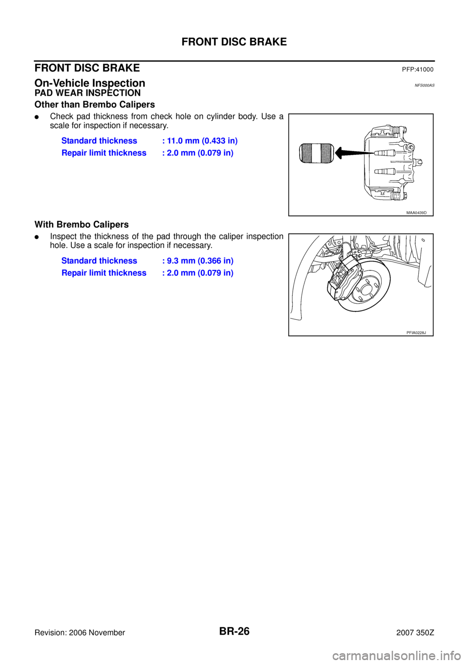
Other than Brembo Calipers
�Check pad thickness from check hole on cylinder body. Use a
scale for inspection if necessary.
With Brembo Calipers
�Inspect the thickness of the pad through the caliper inspection
hole. Use a scale for inspection if necessary. Standard thickness : 11.0 mm (0.433 in)
Repair limit thickness : 2.0 mm (0.079 in)
MAA0439D
Standard thickness : 9.3 mm (0.366 in)
Repair limit thickness : 2.0 mm (0.079 in)
PFIA0228J
Page 27 of 54

FRONT DISC BRAKE
BR-27
C
D
E
G
H
I
J
K
L
MA
B
BR
Revision: 2006 November2007 350Z
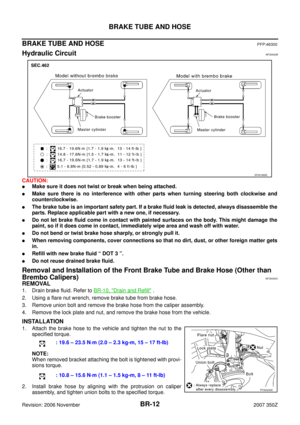
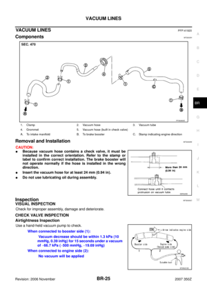
ComponentsNFS000AT
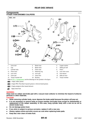
OTHER THAN BREMBO CALIPERS
WARNING:
Clean dust on caliper and brake pad with a vacuum dust collector to minimize the hazard of airborne
particles or other materials.
CAUTION:
�While removing cylinder body, do not depress brake pedal because piston will pop out.
�It is not necessary to remove torque member mounting bolts on torque member and brake hose
except for disassembly or replacement of caliper assembly. In this case, hang cylinder body with a
wire so that brake hose is not under tension.
�Do not damage piston boot.
�If any shim is subject to serious corrosion, replace it with a new one.
�Always replace shim and shim covers as a set when replacing brake pads.
�Keep disc rotor clean of brake fluid.
�Burnish the brake pads and disc rotor mutually contacting surfaces after refinishing or replacing
rotors, after replacing pads, or if a soft pedal occurs at very low mileage. Refer to BR-38, "
Brake
Burnishing Procedure" .
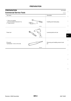
1. Union bolt 2. Copper washer 3. Brake hose
4. Cap 5. Bleed valve 6. Sliding pin bolt
7. Piston seal 8. Piston 9. Piston boot
10. Cylinder body 11. Sliding pin 12. Torque member mounting bolt
13. Washer 14. Sliding pin boot 15. Bushing
16. Torque member 17. inner shim cover 18. inner shim
19. Inner pad 20. Pad retainer 21. Pad wear sensor
22. Outer pad 23. Outer shim 24. Outer shim cover
Refer to GI-11, "
Components" and the followings for the symbols in the figure.
1: Apply rubber grease.
2: Apply PBC (Poly Butyl Cuprysil) grease or silicone-based grease.
3: Apply polyglycol ether based lubricant.
: Apply brake fluid.
PFIA0746J
Page 28 of 54

BR-28
FRONT DISC BRAKE
Revision: 2006 November2007 350Z
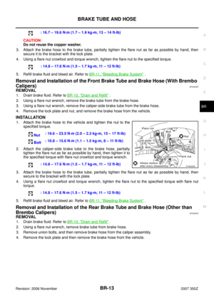
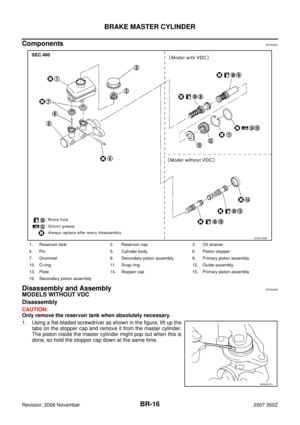
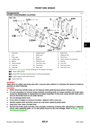
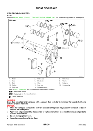
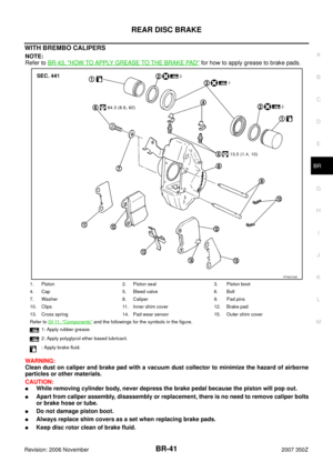
WITH BREMBO CALIPERS
NOTE:
Refer to BR-30, "
HOW TO APPLY GREASE TO THE BRAKE PAD" for how to apply grease to brake pads.
WARNING:
Clean dust on caliper and brake pad with a vacuum dust collector to minimize the hazard of airborne
particles or other materials.
CAUTION:
�While the brake pad and cylinder body are separated, the piston may suddenly jump out, so do not
depress the brake pedal.
�Apart from caliper assembly, disassembly or replacement, there is no need to remove caliper bolts
or brake hose or tube.
�Do not damage piston boot.
�Keep disc rotor clean of brake fluid.
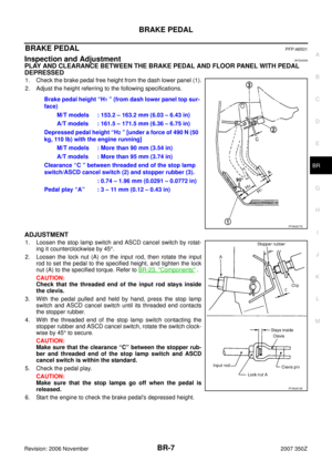
1. Piston 2. Piston seal 3. Piston boot
4. Cap 5. Bleed valve 6. Washer
7. Bolt 8. Clips 9. Pad pins
10. Caliper 11. Inner pad 12. Cross spring
13. Outer pad 14. Pad wear sensor
Refer to GI-11, "
Components" and the followings for the symbols in the figure.
1: Apply rubber grease.
2: Apply polyglycol ether based lubricant.
: Apply brake fluid.
PFIA0674J
Page 29 of 54

FRONT DISC BRAKE
BR-29
C
D
E
G
H
I
J
K
L
MA
B
BR
Revision: 2006 November2007 350Z
�Burnish the brake pads and disc rotor mutually contacting surfaces after refinishing or replacing
rotors, after replacing pads, or if a soft pedal occurs at very low mileage. Refer to BR-38, "
Brake
Burnishing Procedure" .
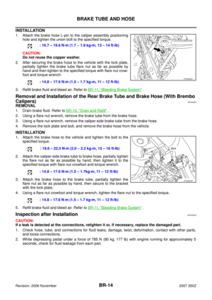
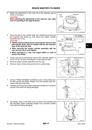
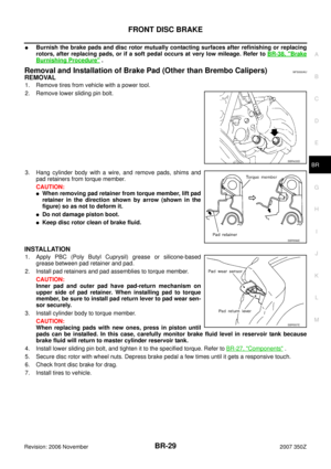
Removal and Installation of Brake Pad (Other than Brembo Calipers)NFS000AU
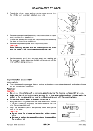
REMOVAL
1. Remove tires from vehicle with a power tool.
2. Remove lower sliding pin bolt.
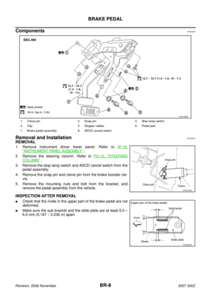
3. Hang cylinder body with a wire, and remove pads, shims and
pad retainers from torque member.
CAUTION:
�When removing pad retainer from torque member, lift pad
retainer in the direction shown by arrow (shown in the
figure) so as not to deform it.
�Do not damage piston boot.
�Keep disc rotor clean of brake fluid.
INSTALLATION
1. Apply PBC (Poly Butyl Cuprysil) grease or silicone-based
grease between pad retainer and pad.
2. Install pad retainers and pad assemblies to torque member.
CAUTION:
Inner pad and outer pad have pad-return mechanism on
upper side of pad retainer. When installing pad to torque
member, be sure to install pad return lever to pad wear sen-
sor securely.
3. Install cylinder body to torque member.
CAUTION:
When replacing pads with new ones, press in piston until
pads can be installed. In this case, carefully monitor brake fluid level in reservoir tank because
brake fluid will return to master cylinder reservoir tank.
4. Install lower sliding pin bolt, and tighten it to the specified torque. Refer to BR-27, "
Components" .
5. Secure disc rotor with wheel nuts. Depress brake pedal a few times until it gets a responsive touch.
6. Check front disc brake for drag.
7. Install tires to vehicle.
SBR433D
SBR556E
SBR557E
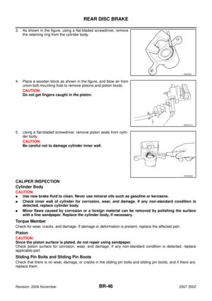
Page 30 of 54
NFS0000W
REMOVAL
1. Remove tires from vehicle with a power tool.
2. Remove the clip")
BR-30
FRONT DISC BRAKE
Revision: 2006 November2007 350Z
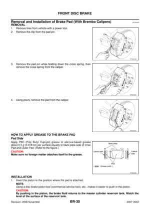
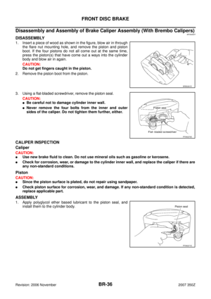
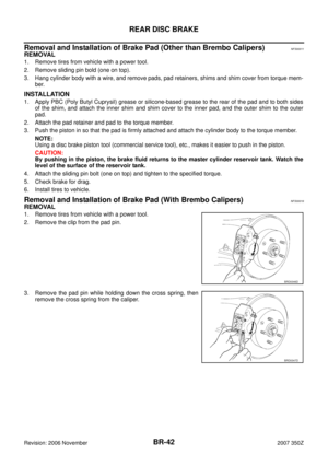
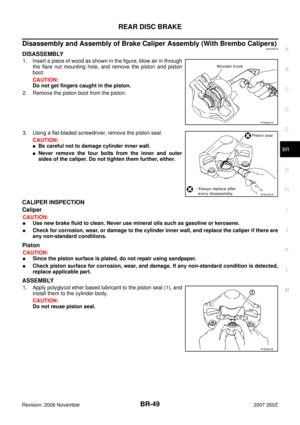
Removal and Installation of Brake Pad (With Brembo Calipers)NFS0000W
REMOVAL
1. Remove tires from vehicle with a power tool.
2. Remove the clip from the pad pin.
3. Remove the pad pin while holding down the cross spring, then
remove the cross spring from the caliper.
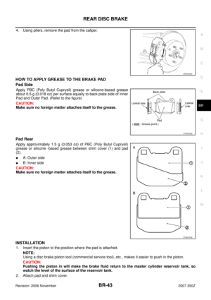
4. Using pliers, remove the pad from the caliper.
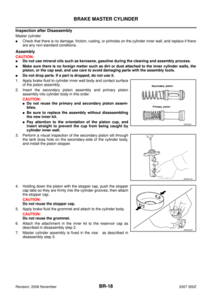
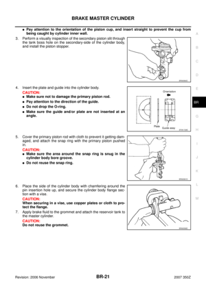
HOW TO APPLY GREASE TO THE BRAKE PAD
Pad Side
Apply PBC (Poly Butyl Cuprysil) grease or silicone-based grease
about 0.5 g (0.018 oz) per surface equally to back plate side of Inner
Pad and Outer Pad. (Refer to the figure.)
CAUTION:
Make sure no foreign matter attaches itself to the grease.
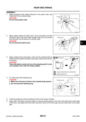
INSTALLATION
1. Insert the piston to the position where the pad is attached.
NOTE:
Using a disc brake piston tool (commercial service tool), etc., makes it easier to push in the piston.
CAUTION:
By pushing in the piston, the brake fluid returns to the master cylinder reservoir tank. Watch the
level of the surface of the reservoir tank.
PFIA0274E
BRB0328D
BRB0329D
PFIA0235E
Page 31 of 54

FRONT DISC BRAKE
BR-31
C
D
E
G
H
I
J
K
L
MA
B
BR
Revision: 2006 November2007 350Z
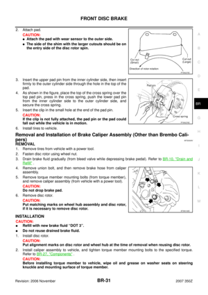
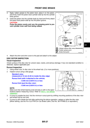
2. Attach pad.
CAUTION:
�Attach the pad with wear sensor to the outer side.
�The side of the shim with the larger cutouts should be on
the entry side of the disc rotor spin.
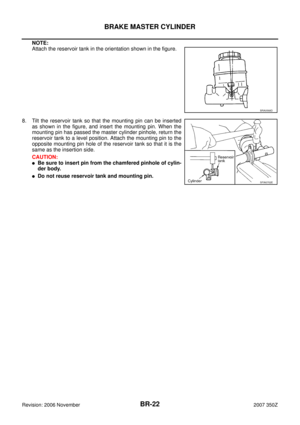
3. Insert the upper pad pin from the inner cylinder side, then insert
firmly to the outer cylinder side through the hole in the top of the
pad.
4. As shown in the figure, place the top of the cross spring over the
top pad pin, press in the cross spring, push the lower pad pin
from the inner cylinder side to the outer cylinder side, and
secure the cross spring.
5. Insert the clip in the small hole at the end of the pad pin.
CAUTION:
If the clip is not fully attached, the pad pin or the pad could
fall out while the vehicle is in motion.
6. Install tires to vehicle.
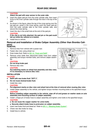
Removal and Installation of Brake Caliper Assembly (Other than Brembo Cali-
pers)
NFS000AV
REMOVAL
1. Remove tires from vehicle with a power tool.
2. Fasten disc rotor using wheel nut.
3. Drain brake fluid gradually (from bleed valve while depressing brake pedal). Refer to BR-10, "
Drain and
Refill" .
4. Remove union bolt, and then remove brake hose from caliper
assembly.
5. Remove torque member mounting bolts (from torque member),
and remove caliper assembly (from vehicle with a power tool).
CAUTION:
Do not drop brake pad.
6. Remove disc rotor.
CAUTION:
Put matching marks on wheel hub assembly and disc rotor,
if it is necessary to remove disc rotor.
INSTALLATION
CAUTION:
�Refill with new brake fluid “DOT 3”.
�Do not reuse drained brake fluid.
1. Install disc rotor.
CAUTION:
Put alignment marks on disc rotor and wheel hub at the time of removal when reusing disc rotor.
2. Install caliper assembly to vehicle, and tighten torque member mounting bolts to the specified torque.
Refer to BR-27, "
Components" .
CAUTION:
Before installing torque member to vehicle, wipe oil and grease on washer seats on steering
knuckle and mounting surface of torque member.
PFIA0275E
PFIA0276E
SFIA0140E
Page 32 of 54

BR-32
FRONT DISC BRAKE
Revision: 2006 November2007 350Z
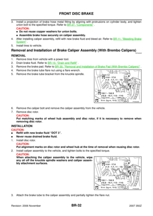
3. Install a projection of brake hose metal fitting by aligning with protrusions on cylinder body, and tighten
union bolt to the specified torque. Refer to BR-27, "
Components" .
CAUTION:
�Do not reuse copper washers for union bolts.
�Assemble brake hose securely on caliper assembly.
4. After installing caliper assembly, refill with new brake fluid and bleed air. Refer to BR-11, "
Bleeding Brake
System" .
5. Install tires to vehicle.
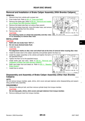
Removal and Installation of Brake Caliper Assembly (With Brembo Calipers)NFS0000X
REMOVAL
1. Remove tires from vehicle with a power tool.
2. Drain brake fluid. Refer to BR-10, "
Drain and Refill" .
3. Remove the brake pad. Refer to BR-30, "
Removal and Installation of Brake Pad (With Brembo Calipers)" .
4. Remove the brake tube flare nut using a flare wrench.
5. Remove the brake tube bracket from the knuckle spindle.
6. Remove the caliper bolt and remove the caliper assembly from the vehicle.
7. Remove disc rotor.
CAUTION:
Put matching marks of wheel hub assembly and disc rotor, if it is necessary to remove when
removing disc rotor.
INSTALLATION
CAUTION:
�Refill with new brake fluid “DOT 3”.
�Never reuse drained brake fluid.
1. Install disc rotor.
CAUTION:
Put alignment marks on disc rotor and wheel hub at the time of removal when reusing disc rotor.
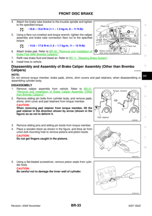
2. Install caliper assembly to the vehicle, and tighten bolts to the specified torque.
CAUTION:
When attaching the caliper assembly to the vehicle, wipe
any oil off the knuckle spindle washers and caliper assem-
bly attachment surfaces.
3. Attach the brake tube to the caliper assembly and partially tighten the flare nut.
PFIA0226E
PFIA0226E