Page 9 of 54
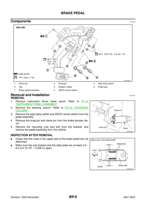
BRAKE PEDAL
BR-9
C
D
E
G
H
I
J
K
L
MA
B
BR
Revision: 2006 November2007 350Z
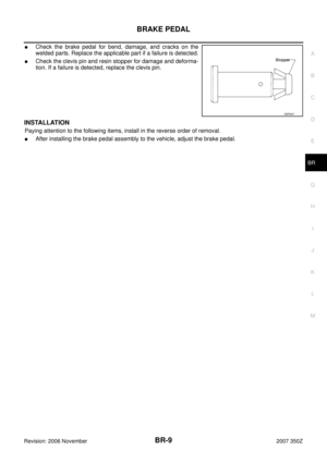
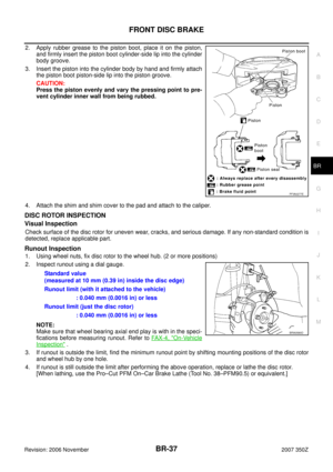
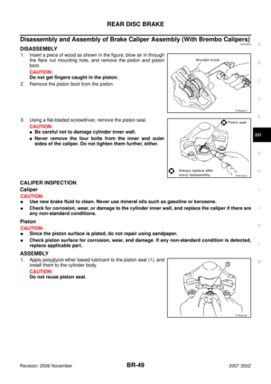
�Check the brake pedal for bend, damage, and cracks on the
welded parts. Replace the applicable part if a failure is detected.
�Check the clevis pin and resin stopper for damage and deforma-
tion. If a failure is detected, replace the clevis pin.
INSTALLATION
Paying attention to the following items, install in the reverse order of removal.
�After installing the brake pedal assembly to the vehicle, adjust the brake pedal.
SBR997
Page 10 of 54

BR-10
BRAKE FLUID
Revision: 2006 November2007 350Z
BRAKE FLUIDPFP:KN100
On-Vehicle InspectionNFS00008
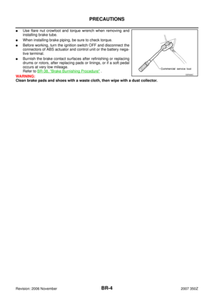
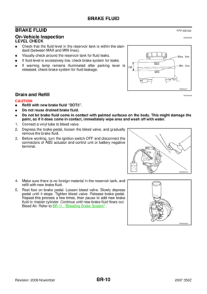
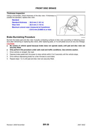
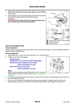
LEVEL CHECK
�Check that the fluid level in the reservoir tank is within the stan-
dard (between MAX and MIN lines).
�Visually check around the reservoir tank for fluid leaks.
�If fluid level is excessively low, check brake system for leaks.
�If warning lamp remains illuminated after parking lever is
released, check brake system for fluid leakage.
Drain and RefillNFS00009
CAUTION:
�Refill with new brake fluid “DOT3”.
�Do not reuse drained brake fluid.
�Do not let brake fluid come in contact with painted surfaces on the body. This might damage the
paint, so if it does come in contact, immediately wipe area and wash off with water.
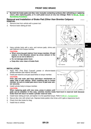
1. Connect a vinyl tube to bleed valve.
2. Depress the brake pedal, loosen the bleed valve, and gradually
remove the brake fluid.
3. Before working, turn the ignition switch OFF and disconnect the
connectors of ABS actuator and control unit or battery negative
terminal.
4. Make sure there is no foreign material in the reservoir tank, and
refill with new brake fluid.
5. Rest foot on brake pedal. Loosen bleed valve. Slowly depress
pedal until it stops. Tighten bleed valve. Release brake pedal.
Repeat this process a few times, then pause to add new brake
fluid to master cylinder. Continue until new brake fluid flows out.
Bleed Air. Refer to BR-11, "
Bleeding Brake System" .
SBR451D
BRA0007D
BRA0006D
Page 11 of 54
BRAKE FLUID
BR-11
C
D
E
G
H
I
J
K
L
MA
B
BR
Revision: 2006 November2007 350Z
Bleeding Brake SystemNFS0000A
CAUTION:
While bleeding, pay attention to master cylinder fluid level.
1. Before working, turn the ignition switch OFF and disconnect the connectors of ABS actuator and control
unit or battery negative terminal.
2. Connect a vinyl tube to the rear right bleed valve.
3. Fully depress brake pedal 4 to 5 times.
4. With the brake pedal depressed, loosen the bleed valve to let the air out, and then tighten it immediately.
5. Repeat steps 3, 4 until no more air comes out.
6. Tighten the bleed valve to the specified torque. Refer to BR-27, "
Components" (Front) and BR-40, "Com-
ponents" (Rear).
7. In steps 2 to 6 below, with the master cylinder reservoir tank filled at least half way, bleed air from the front
left, rear left, and front right tires, in that order.
Page 12 of 54

BR-12
BRAKE TUBE AND HOSE
Revision: 2006 November2007 350Z
BRAKE TUBE AND HOSEPFP:46300
Hydraulic CircuitNFS0000B
CAUTION:
�Make sure it does not twist or break when being attached.
�Make sure there is no interference with other parts when turning steering both clockwise and
counterclockwise.
�The brake tube is an important safety part. If a brake fluid leak is detected, always disassemble the
parts. Replace applicable part with a new one, if necessary.
�Do not let brake fluid come in contact with painted surfaces on the body. This might damage the
paint, so if it does come in contact, immediately wipe area and wash off with water.
�Do not bend or twist brake hose sharply, or strongly pull it.
�When removing components, cover connections so that no dirt, dust, or other foreign matter gets
in.
�Refill with new brake fluid “ DOT 3 ”.
�Do not reuse drained brake fluid.
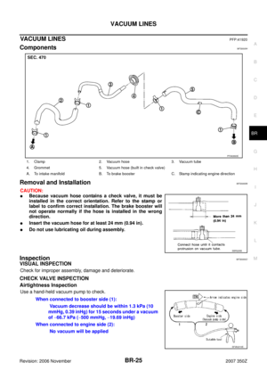
Removal and Installation of the Front Brake Tube and Brake Hose (Other than
Brembo Calipers)
NFS0000C
REMOVAL
1. Drain brake fluid. Refer to BR-10, "Drain and Refill" .
2. Using a flare nut wrench, remove brake tube from brake hose.
3. Remove union bolt and remove the brake hose from the caliper assembly.
4. Remove the lock plate and nut, and remove the brake hose from the vehicle.
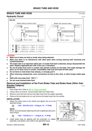
INSTALLATION
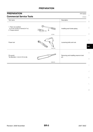
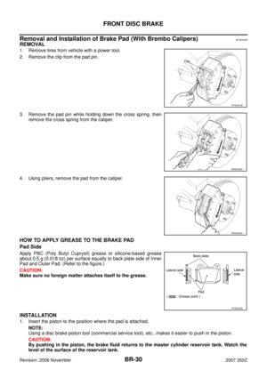
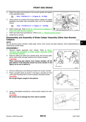
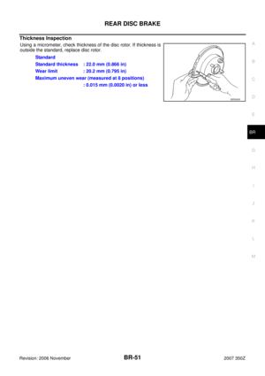
1. Attach the brake hose to the vehicle and tighten the nut to the
specified torque.
NOTE:
When removed bracket attaching the bolt is tightened with provi-
sions torque.
2. Install brake hose by aligning with the protrusion on caliper
assembly, and tighten union bolts to the specified torque.
SFIA1869E
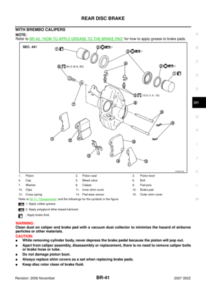
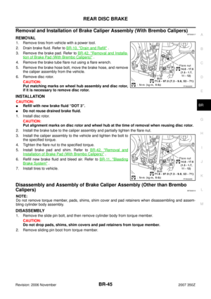
: 19.6 – 23.5 N·m (2.0 – 2.3 kg-m, 15 – 17 ft-lb)
: 10.8 – 15.6 N·m (1.1 – 1.5 kg-m, 8 – 11 ft-lb)
PFIA0230E
Page 13 of 54

BRAKE TUBE AND HOSE
BR-13
C
D
E
G
H
I
J
K
L
MA
B
BR
Revision: 2006 November2007 350Z
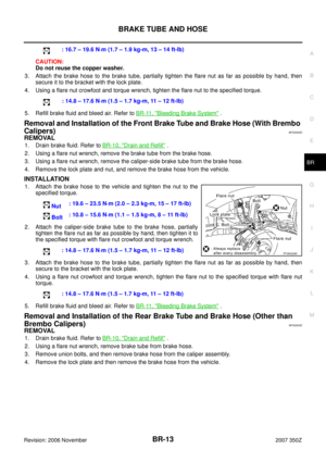
CAUTION:
Do not reuse the copper washer.
3. Attach the brake hose to the brake tube, partially tighten the flare nut as far as possible by hand, then
secure it to the bracket with the lock plate.
4. Using a flare nut crowfoot and torque wrench, tighten the flare nut to the specified torque.
5. Refill brake fluid and bleed air. Refer to BR-11, "
Bleeding Brake System" .
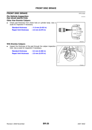
Removal and Installation of the Front Brake Tube and Brake Hose (With Brembo
Calipers)
NFS0000D
REMOVAL
1. Drain brake fluid. Refer to BR-10, "Drain and Refill" .
2. Using a flare nut wrench, remove the brake tube from the brake hose.
3. Using a flare nut wrench, remove the caliper-side brake tube from the brake hose.
4. Remove the lock plate and nut, and remove the brake hose from the vehicle.
INSTALLATION
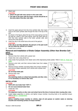
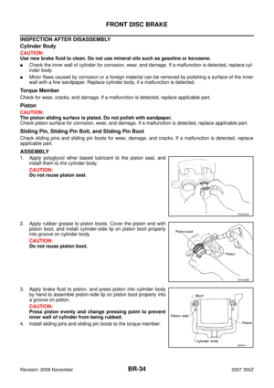
1. Attach the brake hose to the vehicle and tighten the nut to the
specified torque.
2. Attach the caliper-side brake tube to the brake hose, partially
tighten the flare nut as far as possible by hand, then tighten it to
the specified torque with flare nut crowfoot and torque wrench.
3. Attach the brake hose to the brake tube, partially tighten the flare nut as far as possible by hand, then
secure to the bracket with the lock plate.
4. Using a flare nut crowfoot and torque wrench, tighten the flare nut to the specified torque with flare nut
torque.
5. Refill brake fluid and bleed air. Refer to BR-11, "
Bleeding Brake System" .
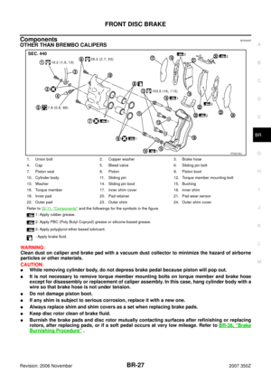
Removal and Installation of the Rear Brake Tube and Brake Hose (Other than
Brembo Calipers)
NFS0000E
REMOVAL
1. Drain brake fluid. Refer to BR-10, "Drain and Refill" .
2. Using a flare nut wrench, remove brake tube from brake hose.
3. Remove union bolts, and then remove brake hose from the caliper assembly.
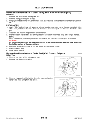
4. Remove the lock plate and then remove the brake hose from the vehicle.: 16.7 – 19.6 N·m (1.7 – 1.9 kg-m, 13 – 14 ft-lb)
: 14.8 – 17.6 N·m (1.5 – 1.7 kg-m, 11 – 12 ft-lb)
Nut: 19.6 – 23.5 N·m (2.0 – 2.3 kg-m, 15 – 17 ft-lb)
Bolt: 10.8 – 15.6 N·m (1.1 – 1.5 kg-m, 8 – 11 ft-lb)
: 14.8 – 17.6 N·m (1.5 – 1.7 kg-m, 11 – 12 ft-lb)
: 14.8 – 17.6 N·m (1.5 – 1.7 kg-m, 11 – 12 ft-lb)
PFIA0229E
Page 14 of 54

BR-14
BRAKE TUBE AND HOSE
Revision: 2006 November2007 350Z
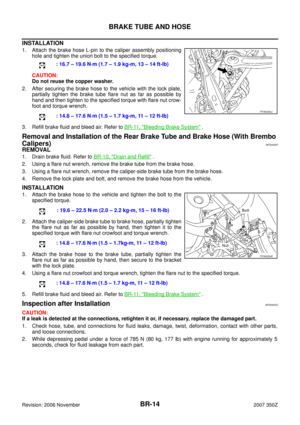
INSTALLATION
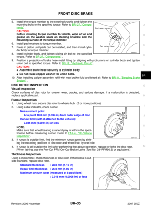
1. Attach the brake hose L-pin to the caliper assembly positioning
hole and tighten the union bolt to the specified torque.
CAUTION:
Do not reuse the copper washer.
2. After securing the brake hose to the vehicle with the lock plate,
partially tighten the brake tube flare nut as far as possible by
hand and then tighten to the specified torque with flare nut crow-
foot and torque wrench.
3. Refill brake fluid and bleed air. Refer to BR-11, "
Bleeding Brake System" .
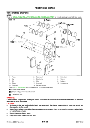
Removal and Installation of the Rear Brake Tube and Brake Hose (With Brembo
Calipers)
NFS0000F
REMOVAL
1. Drain brake fluid. Refer to BR-10, "Drain and Refill" .
2. Using a flare nut wrench, remove the brake tube from the brake hose.
3. Using a flare nut wrench, remove the caliper-side brake tube from the brake hose.
4. Remove the lock plate and bolt, and remove the brake hose from the vehicle.
INSTALLATION
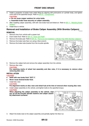
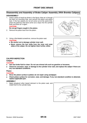
1. Attach the brake hose to the vehicle and tighten the bolt to the
specified torque.
2. Attach the caliper-side brake tube to brake hose, partially tighten
the flare nut as far as possible by hand, then tighten it to the
specified torque with flare nut crowfoot and torque wrench.
3. Attach the brake hose to the brake tube, partially tighten the
flare nut as far as possible by hand, then secure to the bracket
with the lock plate.
4. Using a flare nut crowfoot and torque wrench, tighten the flare nut to the specified torque.
5. Refill brake fluid and bleed air. Refer to BR-11, "
Bleeding Brake System" .
Inspection after InstallationNFS0000G
CAUTION:
If a leak is detected at the connections, retighten it or, if necessary, replace the damaged part.
1. Check hose, tube, and connections for fluid leaks, damage, twist, deformation, contact with other parts,
and loose connections.
2. While depressing pedal under a force of 785 N (80 kg, 177 lb) with engine running for approximately 5
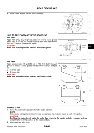
seconds, check for fluid leakage from each part.: 16.7 – 19.6 N·m (1.7 – 1.9 kg-m, 13 – 14 ft-lb)
: 14.8 – 17.6 N·m (1.5 – 1.7 kg-m, 11 – 12 ft-lb)
PFIA0293J
: 19.6 – 22.5 N·m (2.0 – 2.2 kg-m, 15 – 16 ft-lb)
: 14.8 – 17.6 N·m (1.5 – 1.7kg-m, 11 – 12 ft-lb)
: 14.8 – 17.6 N·m (1.5 – 1.7 kg-m, 11 – 12 ft-lb)
PFIA0234E
Page 15 of 54

BRAKE MASTER CYLINDER
BR-15
C
D
E
G
H
I
J
K
L
MA
B
BR
Revision: 2006 November2007 350Z
BRAKE MASTER CYLINDERPFP:46010
On-Vehicle InspectionNFS0000H
LEAK INSPECTION
�Check for leaking in the master cylinder installation surface, the reservoir tank installation surface, and the
brake tube connections.
Removal and InstallationNFS0000I
CAUTION:
Do not let brake fluid come in contact with painted surfaces on the body. This might damage the paint,
so if it does come in contact, immediately wipe area and wash off with water.
REMOVAL
1. Drain brake fluid. Refer to BR-10, "Drain and Refill" .
2. Remove the fluid surface sensor harness connector.
3. Using a flare nut wrench, disconnect master cylinder assembly and brake tube.
4. Remove the master cylinder assembly nut and remove the master cylinder assembly from the vehicle.
Refer to BR-24, "
Removal and Installation" .
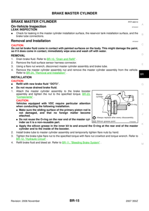
INSTALLATION
CAUTION:
�Refill with new brake fluid “DOT3”.
�Do not reuse drained brake fluid.
1. Attach the master cylinder assembly to the brake booster
assembly and tighten the nut to the specified torque. BR-23,
"Components" .
CAUTION:
Vehicles equipped with VDC require particular attention
when conducting the following installation.
�Make sure the sliding surface of the primary piston rod is
not damaged, and that no foreign matter become
attached.
�Do not reuse the O-ring on the rear end of the master cyl-
inder as it is a non-reusable part.
�Apply the silicon grease in the inner kit to and around the O-ring at the rear end of the master
cylinder and to the inside of the booster.
2. Install brake tube to master cylinder assembly and temporarily tighten flare nuts by hand.
3. Tighten the brake tube flare nut to the specified torque with flare nut crowfoot and torque wrench. Refer to
BR-12, "
Hydraulic Circuit" .
4. Refill brake fluid and bleed air. Refer to BR-11, "
Bleeding Brake System" .
PFIA0296E
Page 16 of 54
BR-16
BRAKE MASTER CYLINDER
Revision: 2006 November2007 350Z
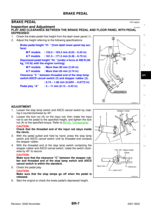
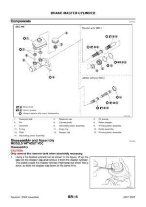
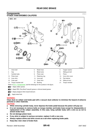
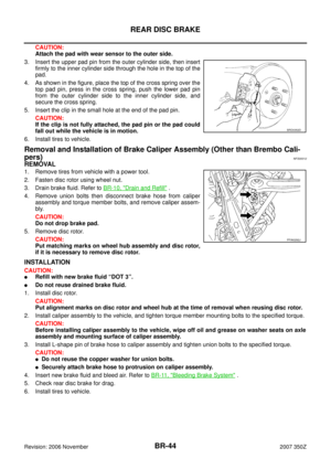
ComponentsNFS0000J
Disassembly and AssemblyNFS0000K
MODELS WITHOUT VDC
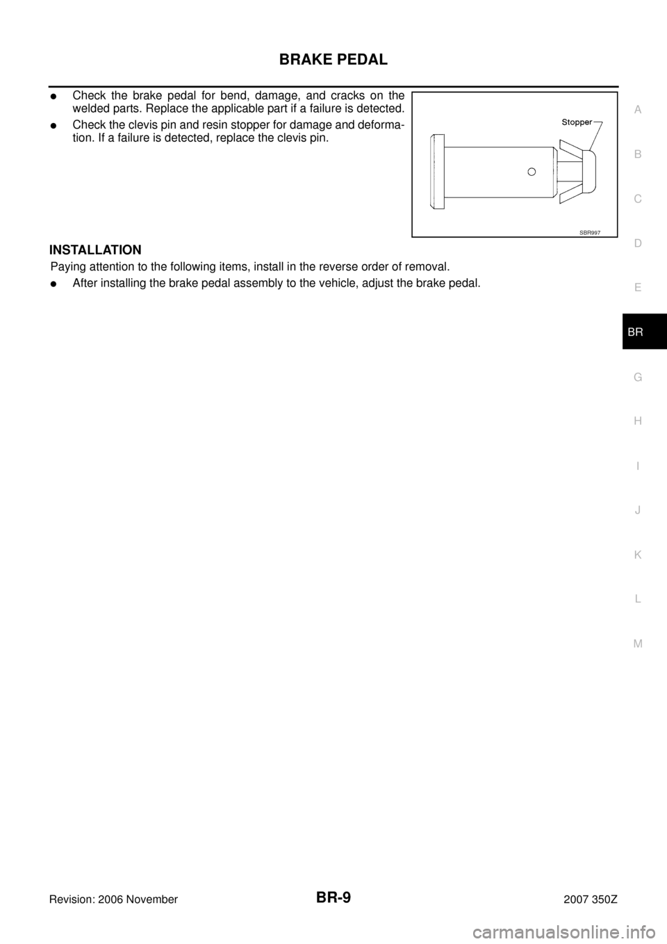
Disassembly
CAUTION:
Only remove the reservoir tank when absolutely necessary.
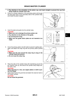
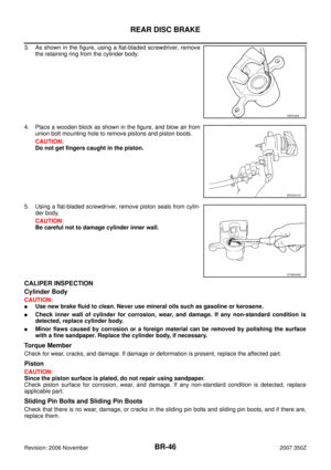
1. Using a flat-bladed screwdriver as shown in the figure, lift up the
tabs on the stopper cap and remove it from the master cylinder.
The piston inside the master cylinder might pop out when this is
done, so hold the stopper cap down at the same time.
1. Reservoir tank 2. Reservoir cap 3. Oil strainer
4. Pin 5. Cylinder body 6. Piston stopper
7. Grommet 8. Secondary piston assembly 9. Primary piston assembly
10. O-ring 11. Snap ring 12. Guide assembly
13. Plate 14. Stopper cap 15. Primary piston assembly
16. Secondary piston assembly
SFIA1728E
BRA0031D