Page 256 of 312
AT-256
DISASSEMBLY
Revision: 2006 November2007 350Z
6. Remove O-ring from input clutch assembly.
7. Remove tightening bolts for oil pump assembly and transmis-
sion case.
8. Attach the sliding hammers to oil pump assembly and extract it
evenly from transmission case.
CAUTION:
�Fully tighten sliding hammer screw.
�Make sure that bearing race is installed to the oil pump
assembly edge surface.
9. Remove O-ring from oil pump assembly.
SCIA5011E
SCIA2300E
SCIA5312E
SCIA5172E
Page 257 of 312
DISASSEMBLY
AT-257
D
E
F
G
H
I
J
K
L
MA
B
AT
Revision: 2006 November2007 350Z
10. Remove bearing race from oil pump assembly.
11. Remove needle bearing from front sun gear.
12. Remove front sun gear assembly from front carrier assembly.
NOTE:
Remove front sun gear by rotating left/right.
13. Remove seal rings from input clutch assembly.
14. Remove front carrier assembly from rear carrier assembly. (With
input clutch assembly and rear internal gear.)
CAUTION:
Be careful to remove it with needle bearing.
SCIA6529E
SCIA2808E
SCIA5014E
SCIA2470E
SCIA5015E
Page 259 of 312
DISASSEMBLY
AT-259
D
E
F
G
H
I
J
K
L
MA
B
AT
Revision: 2006 November2007 350Z
19. Remove needle bearing (front side) from mid carrier assembly.
20. Remove needle bearing (rear side) from mid carrier assembly.
21. Remove bearing race from rear carrier assembly.
22. Remove needle bearing from rear carrier assembly.
23. Remove mid sun gear assembly, rear sun gear assembly and
high and low reverse clutch hub as a unit.
CAUTION:
Be careful to remove then with bearing race and needle
bearing.
SCIA2805E
SCIA2804E
SCIA5175E
SCIA2803E
SCIA5018E
Page 260 of 312
AT-260
DISASSEMBLY
Revision: 2006 November2007 350Z
24. Remove high and low reverse clutch assembly from direct clutch
assembly.
CAUTION:
Make sure that needle bearing is installed to high and low
reverse clutch assembly edge surface.
25. Remove direct clutch assembly from reverse brake.
26. Remove needle bearing from drum support.
27. Remove snap ring from A/T assembly harness connector.
28. Push A/T assembly harness connector.
CAUTION:
Be careful not to damage connector.
SCIA2306E
SCIA5019E
SCIA5198E
SCIA5021E
SCIA5022E
Page 261 of 312
, oil pan (2) and oil pan gasket.
�: Front
�: Oil pan mounting bolt
�Drain bolt (3)
30. Check foreign")
DISASSEMBLY
AT-261
D
E
F
G
H
I
J
K
L
MA
B
AT
Revision: 2006 November2007 350Z
29. Remove clips (1), oil pan (2) and oil pan gasket.
�: Front
�: Oil pan mounting bolt
�Drain bolt (3)
30. Check foreign materials in oil pan to help determine causes of
malfunction. If the ATF is very dark, smells burned, or contains
foreign particles, the frictional material (clutches, band) may
need replacement. A tacky film that will not wipe clean indicates
varnish build up. Varnish can cause valves, servo, and clutches
to stick and can inhibit pump pressure.
�If frictional material is detected, perform A/T fluid cooler
cleaning. Refer to AT- 1 4 , "
A/T Fluid Cooler Cleaning".
31. Remove magnets from oil pan.
32. Disconnect A/T fluid temperature sensor 2 connector (A).
CAUTION:
Be careful not to damage connector.
33. Straighten terminal clips ( ) to free terminal cord assembly and
A/T fluid temperature sensor 2 harness.
34. Disconnect revolution sensor connector.
CAUTION:
Be careful not to damage connector.
SCIA8117E
SCIA5199E
SCIA5200E
SCIA8124E
SCIA7524E
Page 274 of 312
AT-274
REPAIR FOR COMPONENT PARTS
Revision: 2006 November2007 350Z
Front Sun Gear, 3rd One-way ClutchNCS0009D
COMPONENTS
DISASSEMBLY
1. Remove snap ring from front sun gear using a flat-bladed screw-
driver.
2. Remove 3rd one-way clutch from front sun gear.
1. Front sun gear 2. 3rd one-way clutch 3. Snap ring
SCIA3114E
SCIA3110E
S C I A 3 111 E
Page 275 of 312
REPAIR FOR COMPONENT PARTS
AT-275
D
E
F
G
H
I
J
K
L
MA
B
AT
Revision: 2006 November2007 350Z
INSPECTION
3rd One-way Clutch
�Check frictional surface for wear or damage.
CAUTION:
If necessary, replace 3rd one-way clutch.
Front Sun Gear Snap Ring
�Check for deformation, fatigue or damage.
CAUTION:
If necessary, replace snap ring.
Front Sun Gear
�Check for deformation, fatigue or damage.
CAUTION:
If necessary, replace front sun gear.
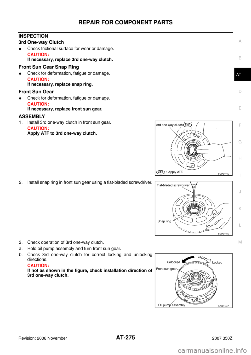
ASSEMBLY
1. Install 3rd one-way clutch in front sun gear.
CAUTION:
Apply ATF to 3rd one-way clutch.
2. Install snap ring in front sun gear using a flat-bladed screwdriver.
3. Check operation of 3rd one-way clutch.
a. Hold oil pump assembly and turn front sun gear.
b. Check 3rd one-way clutch for correct locking and unlocking
directions.
CAUTION:
If not as shown in the figure, check installation direction of
3rd one-way clutch.
S C I A 3 111 E
SCIA3110E
SCIA3131E
Page 276 of 312
AT-276
REPAIR FOR COMPONENT PARTS
Revision: 2006 November2007 350Z
Front Carrier, Input Clutch, Rear Internal GearNCS0009E
COMPONENTS
1. Seal ring 2. O-ring 3. Needle bearing
4. Bearing race 5. Front carrier assembly 6. Needle bearing
7. Snap ring 8. Snap ring 9. Retaining plate
10. Driven plate 11. Input clutch drum 12. Drive plate
13. Rear internal gear
Refer to GI section to make sure icons (symbol marks) in the figure. Refer to GI-11, "
Components" .
SCIA6734E


 from mid carrier assembly.
20. Remove needle bearing (rear side) from mid carrier a")