Page 151 of 312

DTC P1767 HIGH AND LOW REVERSE CLUTCH SOLENOID VALVE
AT-151
D
E
F
G
H
I
J
K
L
MA
B
AT
Revision: 2006 November2007 350Z
DTC P1767 HIGH AND LOW REVERSE CLUTCH SOLENOID VALVEPFP:31940
DescriptionNCS0006C
High and low reverse clutch solenoid valve is controlled by the TCM in response to signals sent from the PNP
switch, vehicle speed sensor and accelerator pedal position sensor (throttle position sensor). Gears will then
be shifted to the optimum position.
CONSULT-III Reference ValueNCS0006D
On Board Diagnosis LogicNCS0006E
�This is an OBD-II self-diagnostic item.
�Diagnostic trouble code “P1767 HLR/C SOL/CIRC” with CONSULT-III or 8th judgment flicker without
CONSULT-III is detected under the following conditions.
–When TCM detects an improper voltage drop when it tries to operate the solenoid valve.
–When TCM detects as irregular by comparing target value with monitor value.
Possible CauseNCS0006F
�Harness or connectors
(Solenoid circuit is open or shorted.)
�High and low reverse clutch solenoid valve
DTC Confirmation ProcedureNCS0006G
CAUTION:
Always drive vehicle at a safe speed.
NOTE:
If “DTC Confirmation Procedure” has been previously performed, always turn ignition switch OFF and
wait at least 10 seconds before performing the next test.
After the repair, perform the following procedure to confirm the malfunction is eliminated.
WITH CONSULT-III
1. Turn ignition switch ON.
2. Select “SELECTION FROM MENU” in “DATA MONITOR” mode for “TRANSMISSION” with CONSULT-III
and check monitor “ACCELE POSI”, “SLCT LVR POSI” and “GEAR”.
3. Touch “START”.
4. Start engine.
5. Drive vehicle and maintain the following conditions for at least 5 consecutive seconds.
ACCELE POSI: 1.5/8 – 2.0/8
SLCT LVR POSI: “D” position
GEAR: “2” � “3” (HLR/C ON/OFF)
Driving location: Driving the vehicle uphill (increased engine load) will help maintain the driving
conditions required for this test.
6. If DTC is detected, go to AT- 1 5 2 , "
Diagnostic Procedure" .
WITH GST
Follow the procedure “WITH CONSULT-III”.
Item name Condition Display value (Approx.)
HLR/C SOLHigh and low reverse clutch disengaged. Refer to AT- 1 9
. 0.6 – 0.8 A
High and low reverse clutch engaged. Refer to AT- 1 9
. 0 – 0.05 A
Page 152 of 312
AT-152
DTC P1767 HIGH AND LOW REVERSE CLUTCH SOLENOID VALVE
Revision: 2006 November2007 350Z
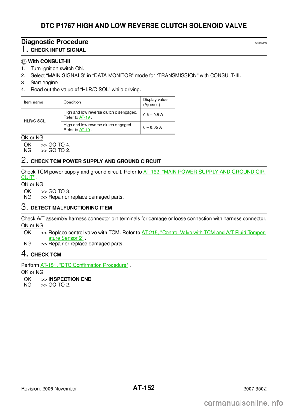
Diagnostic ProcedureNCS0006H
1. CHECK INPUT SIGNAL
With CONSULT-III
1. Turn ignition switch ON.
2. Select “MAIN SIGNALS” in “DATA MONITOR” mode for “TRANSMISSION” with CONSULT-III.
3. Start engine.
4. Read out the value of “HLR/C SOL” while driving.
OK or NG
OK >> GO TO 4.
NG >> GO TO 2.
2. CHECK TCM POWER SUPPLY AND GROUND CIRCUIT
Check TCM power supply and ground circuit. Refer to AT- 1 6 2 , "
MAIN POWER SUPPLY AND GROUND CIR-
CUIT" .
OK or NG
OK >> GO TO 3.
NG >> Repair or replace damaged parts.
3. DETECT MALFUNCTIONING ITEM
Check A/T assembly harness connector pin terminals for damage or loose connection with harness connector.
OK or NG
OK >> Replace control valve with TCM. Refer to AT- 2 1 5 , "Control Valve with TCM and A/T Fluid Temper-
ature Sensor 2" .
NG >> Repair or replace damaged parts.
4. CHECK TCM
Perform AT- 1 5 1 , "
DTC Confirmation Procedure" .
OK or NG
OK >>INSPECTION END
NG >> GO TO 2.
Item name ConditionDisplay value
(Approx.)
HLR/C SOLHigh and low reverse clutch disengaged.
Refer to AT- 1 9
.0.6 – 0.8 A
High and low reverse clutch engaged.
Refer to AT- 1 9
.0 – 0.05 A
Page 216 of 312
AT-216
ON-VEHICLE SERVICE
Revision: 2006 November2007 350Z
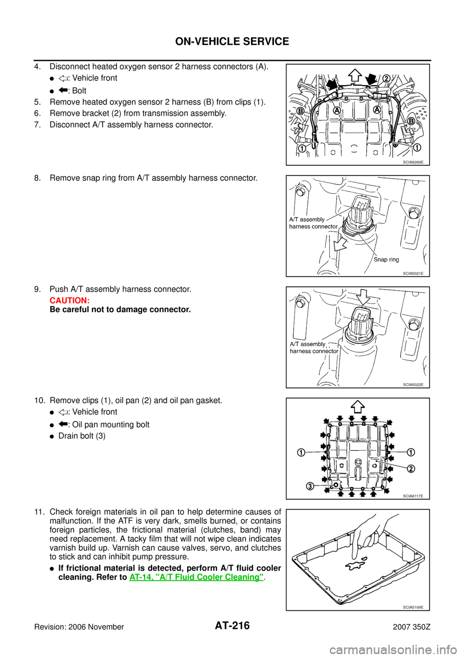
4. Disconnect heated oxygen sensor 2 harness connectors (A).
�: Vehicle front
�: Bolt
5. Remove heated oxygen sensor 2 harness (B) from clips (1).
6. Remove bracket (2) from transmission assembly.
7. Disconnect A/T assembly harness connector.
8. Remove snap ring from A/T assembly harness connector.
9. Push A/T assembly harness connector.
CAUTION:
Be careful not to damage connector.
10. Remove clips (1), oil pan (2) and oil pan gasket.
�: Vehicle front
�: Oil pan mounting bolt
�Drain bolt (3)
11. Check foreign materials in oil pan to help determine causes of
malfunction. If the ATF is very dark, smells burned, or contains
foreign particles, the frictional material (clutches, band) may
need replacement. A tacky film that will not wipe clean indicates
varnish build up. Varnish can cause valves, servo, and clutches
to stick and can inhibit pump pressure.
�If frictional material is detected, perform A/T fluid cooler
cleaning. Refer to AT- 1 4 , "
A/T Fluid Cooler Cleaning".
SCIA8269E
SCIA5021E
SCIA5022E
SCIA8117E
SCIA5199E
Page 224 of 312
AT-224
ON-VEHICLE SERVICE
Revision: 2006 November2007 350Z
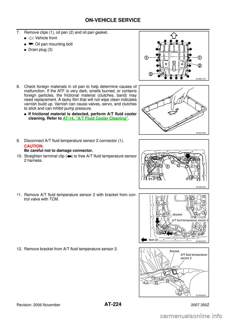
7. Remove clips (1), oil pan (2) and oil pan gasket.
�: Vehicle front
�: Oil pan mounting bolt
�Drain plug (3)
8. Check foreign materials in oil pan to help determine causes of
malfunction. If the ATF is very dark, smells burned, or contains
foreign particles, the frictional material (clutches, band) may
need replacement. A tacky film that will not wipe clean indicates
varnish build up. Varnish can cause valves, servo, and clutches
to stick and can inhibit pump pressure.
�If frictional material is detected, perform A/T fluid cooler
cleaning. Refer to AT- 1 4 , "
A/T Fluid Cooler Cleaning".
9. Disconnect A/T fluid temperature sensor 2 connector (1).
CAUTION:
Be careful not to damage connector.
10. Straighten terminal clip ( ) to free A/T fluid temperature sensor
2 harness.
11. Remove A/T fluid temperature sensor 2 with bracket from con-
trol valve with TCM.
12. Remove bracket from A/T fluid temperature sensor 2.
SCIA8117E
SCIA5199E
SCIA8076E
SCIA5302E
SCIA5264E
Page 236 of 312
AT-236
ON-VEHICLE SERVICE
Revision: 2006 November2007 350Z
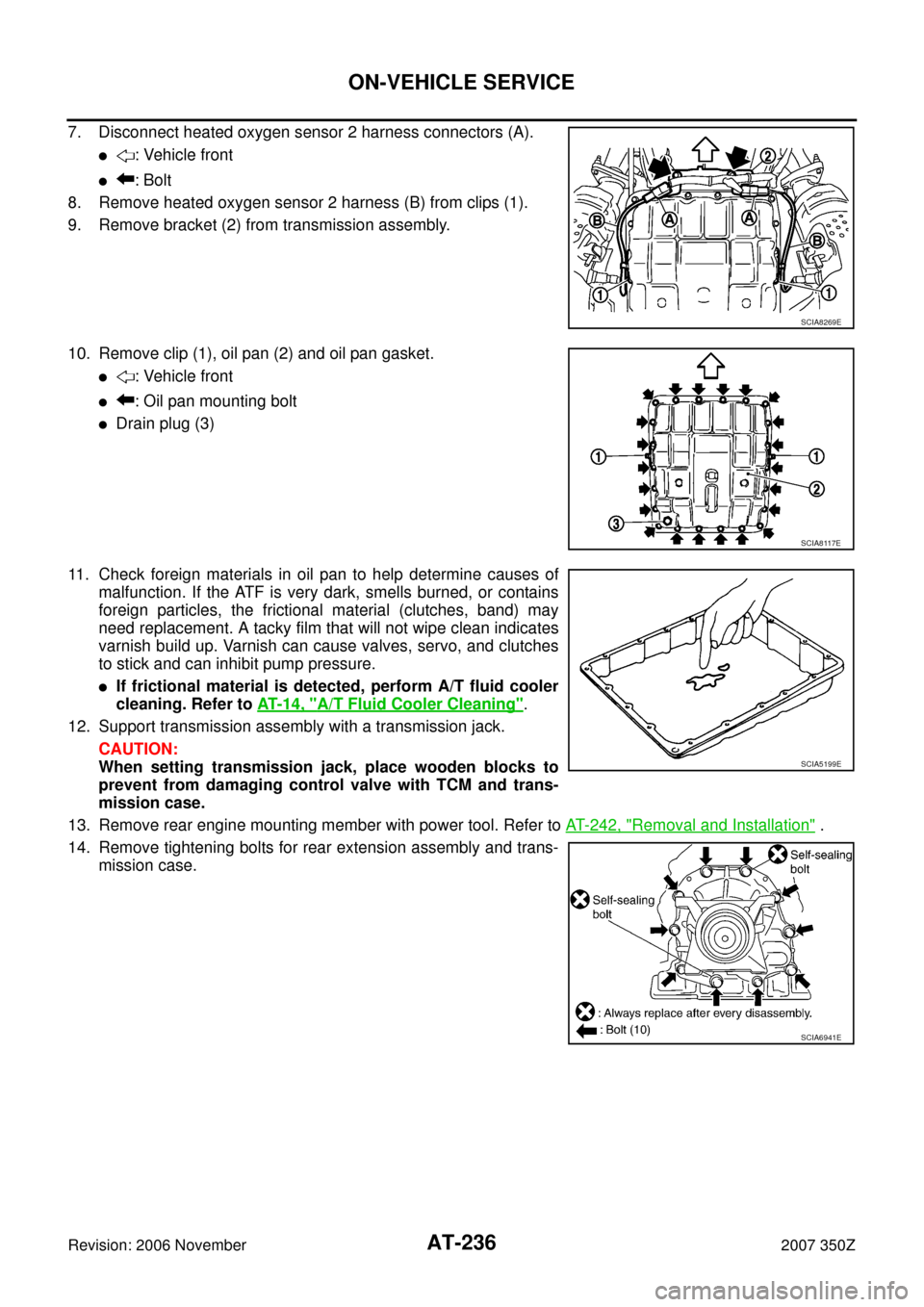
7. Disconnect heated oxygen sensor 2 harness connectors (A).
�: Vehicle front
�: Bolt
8. Remove heated oxygen sensor 2 harness (B) from clips (1).
9. Remove bracket (2) from transmission assembly.
10. Remove clip (1), oil pan (2) and oil pan gasket.
�: Vehicle front
�: Oil pan mounting bolt
�Drain plug (3)
11. Check foreign materials in oil pan to help determine causes of
malfunction. If the ATF is very dark, smells burned, or contains
foreign particles, the frictional material (clutches, band) may
need replacement. A tacky film that will not wipe clean indicates
varnish build up. Varnish can cause valves, servo, and clutches
to stick and can inhibit pump pressure.
�If frictional material is detected, perform A/T fluid cooler
cleaning. Refer to AT- 1 4 , "
A/T Fluid Cooler Cleaning".
12. Support transmission assembly with a transmission jack.
CAUTION:
When setting transmission jack, place wooden blocks to
prevent from damaging control valve with TCM and trans-
mission case.
13. Remove rear engine mounting member with power tool. Refer to AT- 2 4 2 , "
Removal and Installation" .
14. Remove tightening bolts for rear extension assembly and trans-
mission case.
SCIA8269E
SCIA8117E
SCIA5199E
SCIA6941E
Page 247 of 312
OVERHAUL
AT-247
D
E
F
G
H
I
J
K
L
MA
B
AT
Revision: 2006 November2007 350Z
1. O-ring 2. Oil pump cover 3. O-ring
4. Oil pump housing 5. Self-sealing bolt 6. Torque converter
7. Converter housing 8. Oil pump housing oil seal 9. Bearing race
10. Needle bearing 11. O-ring 12. Front carrier assembly
13. Needle bearing 14. Snap ring 15. Front sun gear
16. 3rd one-way clutch 17. Snap ring 18. Bearing race
19. Needle bearing 20. Seal ring 21. Input clutch assembly
22. Needle bearing 23. Rear internal gear 24. Brake band
25. Mid carrier assembly 26. Needle bearing 27. Bearing race
28. Rear carrier assembly 29. Needle bearing 30. Mid sun gear
31. Seal ring 32. Rear sun gear 33. 1st one-way clutch
34. Snap ring 35. Needle bearing 36. High and low reverse clutch hub
37. Snap ring 38. Bearing race 39. Needle bearing
Refer to GI section to make sure icons (symbol marks) in the figure. Refer to GI-11, "
Components" .
However, refer to the following for others.
: Apply Genuine RTV silicone sealant or equivalent. Refer to GI-45, "
Recommended Chemical Products and Sealants" .
Page 248 of 312
AT-248
OVERHAUL
Revision: 2006 November2007 350Z
1. Needle bearing 2. Bearing race 3. High and low reverse clutch assembly
4. Needle bearing 5. Direct clutch assembly 6. Reverse brake dish plate
7. Reverse brake dish plate 8. Reverse brake driven plate 9. N-spring
SCIA8377E
Page 255 of 312
DISASSEMBLY
AT-255
D
E
F
G
H
I
J
K
L
MA
B
AT
Revision: 2006 November2007 350Z
DISASSEMBLYPFP:31020
DisassemblyNCS0009B
CAUTION:
Do not disassemble parts behind Drum Support. Refer to AT- 1 7 , "
Cross-sectional View" .
1. Drain ATF through drain hole.
2. Remove torque converter by holding it firmly and turing while
pulling straight out.
3. Check torque converter one-way clutch using check tool as
shown at figure.
a. Insert check tool into the groove of bearing support built into
one-way clutch outer race.
b. When fixing bearing support with check tool, rotate one- way
clutch spline using screwdriver.
c. Check that inner race rotates clockwise only. If not, replace
torque converter assembly.
4. Remove tightening bolts ( ) for converter housing and trans-
mission case.
5. Remove converter housing from transmission case.
CAUTION:
Be careful not to scratch converter housing.
SCIA5010E
SCIA3171E
SCIA8096E