Page 285 of 312

REPAIR FOR COMPONENT PARTS
AT-285
D
E
F
G
H
I
J
K
L
MA
B
AT
Revision: 2006 November2007 350Z
5. Install needle bearing to high and low reverse clutch hub.
CAUTION:
�Take care with the direction of needle bearing. Refer to
AT- 2 5 3 , "
Locations of Adjusting Shims, Needle Bearings,
Thrust Washers and Snap Rings" .
�Apply petroleum jelly to needle bearing.
6. Install high and low reverse clutch hub to mid sun gear assem-
bly.
7. Install snap ring to mid sun gear assembly using pair of snap
ring pliers.
CAUTION:
Do not expand snap ring excessively.
8. Check operation of 1st one-way clutch.
a. Hold mid sun gear and turn rear sun gear.
b. Check 1st one-way clutch for correct locking and unlocking
directions.
CAUTION:
If not as shown in illustration, check installation direction of
1st one-way clutch.
9. Install bearing race and needle bearing to high and low reverse
clutch hub.
CAUTION:
�Take care with the direction of needle bearing. Refer to
AT- 2 5 3 , "
Locations of Adjusting Shims, Needle Bearings,
Thrust Washers and Snap Rings" .
�Apply petroleum jelly to needle bearing.
SCIA2857E
SCIA2856E
SCIA2855E
SCIA3132E
SCIA2854E
Page 286 of 312
AT-286
REPAIR FOR COMPONENT PARTS
Revision: 2006 November2007 350Z
High and Low Reverse ClutchNCS0009G
COMPONENTS
DISASSEMBLY
1. Remove bearing race from high and low reverse clutch drum.
2. Remove snap ring from high and low reverse clutch drum using
a flat-bladed screwdriver.
3. Remove retaining plate, drive plates and driven plates from high
and low reverse clutch drum.
1. High and low reverse clutch drum 2. Driven plate 3. Retaining plate
4. Snap ring 5. Drive plate 6. Bearing race
SCIA5045E
SCIA5215E
SCIA2868E
Page 287 of 312
REPAIR FOR COMPONENT PARTS
AT-287
D
E
F
G
H
I
J
K
L
MA
B
AT
Revision: 2006 November2007 350Z
INSPECTION
Check the following, and replace high and low reverse clutch assembly if necessary.
High and Low Reverse Clutch Snap Ring
�Check for deformation, fatigue or damage.
High and Low Reverse Clutch Drive Plates
�Check facing for burns, cracks or damage.
High and Low Reverse Clutch Retaining Plate and Driven Plates
�Check facing for burns, cracks or damage.
ASSEMBLY
1. Install driven plates, drive plates and retaining plate in high and low reverse clutch drum.
CAUTION:
Take care with order of plates.
2. Install snap ring in high and low reverse clutch drum using a flat-
bladed screwdriver.
3. Install bearing race to high and low reverse clutch drum.
CAUTION:
Apply petroleum jelly to bearing race.
SCIA2868E
SCIA5215E
Page 288 of 312
AT-288
REPAIR FOR COMPONENT PARTS
Revision: 2006 November2007 350Z
Direct ClutchNCS0009H
COMPONENTS
DISASSEMBLY
1. Remove snap ring from direct clutch drum using a flat-bladed
screwdriver.
2. Remove retaining plates, drive plates, driven plates and dish
plate from direct clutch drum.
INSPECTION
Check the following, and replace direct clutch assembly if necessary.
Direct Clutch Snap Ring
�Check for deformation, fatigue or damage.
Direct Clutch Drive Plates
�Check facing for burns, cracks or damage.
Direct Clutch Retaining Plate, Driven Plates and Dish Plate
�Check facing for burns, cracks or damage.
1. Direct clutch drum 2. Dish plate 3. Retaining plate
4. Driven plate 5. Retaining plate 6. Snap ring
7. Drive plate
SCIA7015E
SCIA2868E
Page 289 of 312
REPAIR FOR COMPONENT PARTS
AT-289
D
E
F
G
H
I
J
K
L
MA
B
AT
Revision: 2006 November2007 350Z
ASSEMBLY
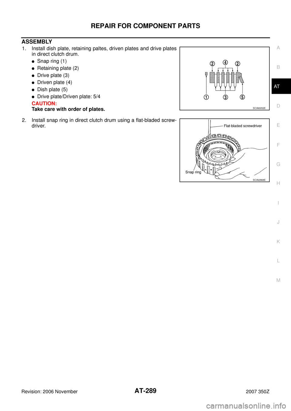
1. Install dish plate, retaining paltes, driven plates and drive plates
in direct clutch drum.
�Snap ring (1)
�Retaining plate (2)
�Drive plate (3)
�Driven plate (4)
�Dish plate (5)
�Drive plate/Driven plate: 5/4
CAUTION:
Take care with order of plates.
2. Install snap ring in direct clutch drum using a flat-bladed screw-
driver.
SCIA6952E
SCIA2868E
Page 298 of 312
AT-298
ASSEMBLY
Revision: 2006 November2007 350Z
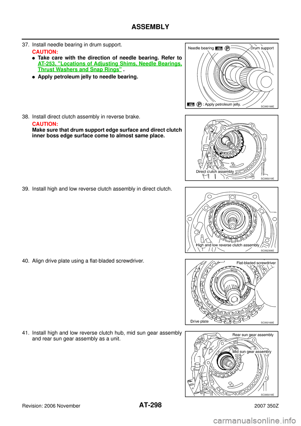
37. Install needle bearing in drum support.
CAUTION:
�Take care with the direction of needle bearing. Refer to
AT- 2 5 3 , "
Locations of Adjusting Shims, Needle Bearings,
Thrust Washers and Snap Rings" .
�Apply petroleum jelly to needle bearing.
38. Install direct clutch assembly in reverse brake.
CAUTION:
Make sure that drum support edge surface and direct clutch
inner boss edge surface come to almost same place.
39. Install high and low reverse clutch assembly in direct clutch.
40. Align drive plate using a flat-bladed screwdriver.
41. Install high and low reverse clutch hub, mid sun gear assembly
and rear sun gear assembly as a unit.
SCIA5198E
SCIA5019E
SCIA2306E
SCIA3169E
SCIA5018E
Page 299 of 312
ASSEMBLY
AT-299
D
E
F
G
H
I
J
K
L
MA
B
AT
Revision: 2006 November2007 350Z
CAUTION:
Make sure that portion “A” of high and low reverse clutch
drum protrudes approximately 2 mm (0.08 in) beyond por-
tion “B” of rear sun gear.
42. Install needle bearing in rear carrier assembly.
CAUTION:
�Take care with the direction of needle bearing. Refer to
AT- 2 5 3 , "
Locations of Adjusting Shims, Needle Bearings,
Thrust Washers and Snap Rings" .
�Apply petroleum jelly to needle bearing.
43. Install bearing race in rear carrier assembly.
CAUTION:
Apply petroleum jelly to bearing race.
44. Install rear carrier assembly in direct clutch drum.
SCIA3130E
SCIA2803E
SCIA5175E
SCIA2462E
Page 300 of 312
AT-300
ASSEMBLY
Revision: 2006 November2007 350Z
45. Install needle bearing (rear side) to mid carrier assembly.
CAUTION:
�Take care with the direction of needle bearing. Refer to
AT- 2 5 3 , "
Locations of Adjusting Shims, Needle Bearings,
Thrust Washers and Snap Rings" .
�Apply petroleum jelly to needle bearing.
46. Install needle bearing (front side) to mid carrier assembly.
CAUTION:
�Take care with the direction of needle bearing. Refer to
AT- 2 5 3 , "
Locations of Adjusting Shims, Needle Bearings,
Thrust Washers and Snap Rings" .
�Apply petroleum jelly to needle bearing.
47. Install mid carrier assembly in rear carrier assembly.
48. Install front carrier assembly, input clutch assembly and rear
internal gear as a unit.
49. Install seal rings in input clutch assembly.
CAUTION:
�Do not reuse seal rings.
�Apply petroleum jelly to seal rings.
SCIA2804E
SCIA2805E
SCIA5017E
SCIA5015E
SCIA2470E


 beyond por")
