Page 277 of 312
REPAIR FOR COMPONENT PARTS
AT-277
D
E
F
G
H
I
J
K
L
MA
B
AT
Revision: 2006 November2007 350Z
DISASSEMBLY
1. Compress snap ring using 2 flat-bladed screwdrivers.
2. Remove front carrier assembly and input clutch assembly from
rear internal gear.
3. Remove front carrier assembly from input clutch assembly.
a. Remove bearing race from front carrier assembly.
b. Remove needle bearing from front carrier assembly.
c. Remove snap ring from front carrier assembly.
CAUTION:
Do not expand snap ring excessively.
SCIA7475E
SCIA2847E
SCIA5233E
SCIA5476E
Page 278 of 312
AT-278
REPAIR FOR COMPONENT PARTS
Revision: 2006 November2007 350Z
4. Disassemble input clutch assembly.
a. Remove O-ring and seal rings from input clutch assembly.
b. Remove needle bearing from input clutch assembly.
c. Remove snap ring from input clutch drum using a flat-bladed
screwdriver.
d. Remove retaining plate, drive plates and driven plates from input
clutch drum.
INSPECTION
Front Carrier Snap Ring
�Check for deformation, fatigue or damage.
CAUTION:
If necessary, replace snap ring.
Input Clutch Snap Ring
�Check for deformation, fatigue or damage.
CAUTION:
If necessary, replace input clutch assembly.
Input Clutch Drum
�Check for deformation, fatigue or damage or burns.
CAUTION:
If necessary, replace input clutch assembly.
Input Clutch Drive Plates
�Check facing for burns, cracks or damage.
CAUTION:
If necessary, replace input clutch assembly.
Input Clutch Retaining Plate and Driven Plates
�Check facing for burns, cracks or damage.
SCIA5235E
SCIA2853E
SCIA2864E
Page 279 of 312

REPAIR FOR COMPONENT PARTS
AT-279
D
E
F
G
H
I
J
K
L
MA
B
AT
Revision: 2006 November2007 350Z
CAUTION:
If necessary, replace input clutch assembly.
Front Carrier
�Check for deformation, fatigue or damage.
CAUTION:
If necessary, replace front carrier assembly.
Rear Internal Gear
�Check for deformation, fatigue or damage.
CAUTION:
If necessary, replace rear internal gear.
ASSEMBLY
1. Install input clutch.
a. Install driven plates, drive plates and retaining plate in input
clutch drum.
�Snap ring (1)
�Retaining plate (2)
�Drive plate (3)
�Driven plate (4)
�Drive plate/Driven plate: 7/7
CAUTION:
Take care with order of plates.
b. Install snap ring in input clutch drum using a flat-bladed screw-
driver.
c. Install needle bearing in input clutch assembly.
CAUTION:
�Take care with the direction of needle bearing. Refer to
AT- 2 5 3 , "
Locations of Adjusting Shims, Needle Bearings,
Thrust Washers and Snap Rings" .
�Apply petroleum jelly to needle bearing.
SCIA7133E
SCIA2864E
SCIA2853E
Page 280 of 312
AT-280
REPAIR FOR COMPONENT PARTS
Revision: 2006 November2007 350Z
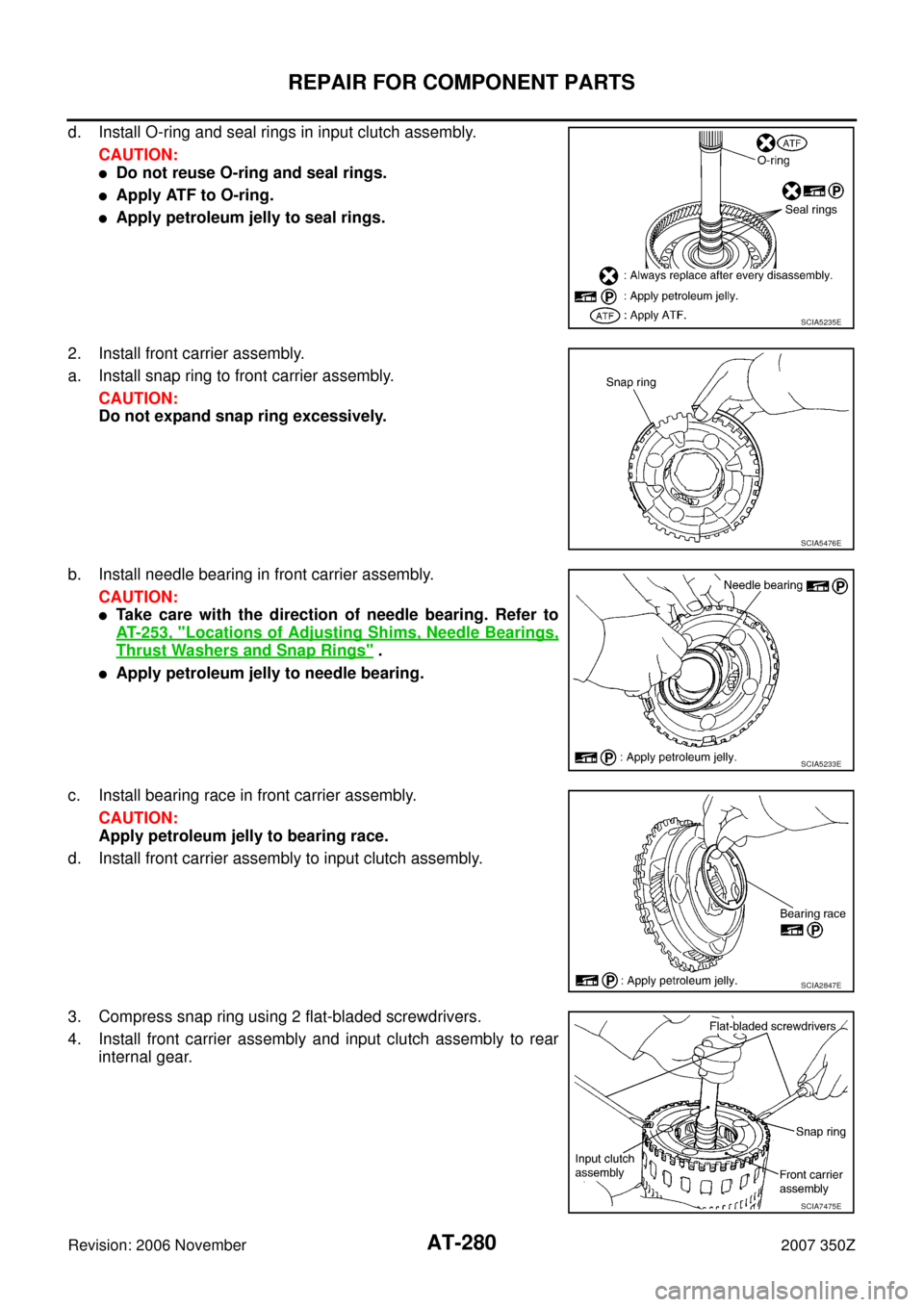
d. Install O-ring and seal rings in input clutch assembly.
CAUTION:
�Do not reuse O-ring and seal rings.
�Apply ATF to O-ring.
�Apply petroleum jelly to seal rings.
2. Install front carrier assembly.
a. Install snap ring to front carrier assembly.
CAUTION:
Do not expand snap ring excessively.
b. Install needle bearing in front carrier assembly.
CAUTION:
�Take care with the direction of needle bearing. Refer to
AT- 2 5 3 , "
Locations of Adjusting Shims, Needle Bearings,
Thrust Washers and Snap Rings" .
�Apply petroleum jelly to needle bearing.
c. Install bearing race in front carrier assembly.
CAUTION:
Apply petroleum jelly to bearing race.
d. Install front carrier assembly to input clutch assembly.
3. Compress snap ring using 2 flat-bladed screwdrivers.
4. Install front carrier assembly and input clutch assembly to rear
internal gear.
SCIA5235E
SCIA5476E
SCIA5233E
SCIA2847E
SCIA7475E
Page 281 of 312
REPAIR FOR COMPONENT PARTS
AT-281
D
E
F
G
H
I
J
K
L
MA
B
AT
Revision: 2006 November2007 350Z
Mid Sun Gear, Rear Sun Gear, High and Low Reverse Clutch HubNCS0009F
COMPONENTS
DISASSEMBLY
1. Remove needle bearing and bearing race from high and low
reverse clutch hub.
2. Remove snap ring from mid sun gear assembly using pair of
snap ring pliers.
CAUTION:
Do not expand snap ring excessively.
1. Needle bearing 2. Bearing race 3. Snap ring
4. High and low reverse clutch hub 5. Needle bearing 6. Snap ring
7. 1st one-way clutch 8. Rear sun gear 9. Seal ring
10. Mid sun gear
SCIA2851E
SCIA2854E
SCIA2855E
Page 282 of 312
AT-282
REPAIR FOR COMPONENT PARTS
Revision: 2006 November2007 350Z
3. Remove high and low reverse clutch hub from mid sun gear
assembly.
a. Remove needle bearing from high and low reverse clutch hub.
4. Remove rear sun gear assembly (1) from mid sun gear assem-
bly.
a. Remove snap ring from rear sun gear using a flat-bladed screw-
driver.
SCIA2856E
SCIA2857E
SCIA8155E
SCIA2859E
Page 283 of 312
REPAIR FOR COMPONENT PARTS
AT-283
D
E
F
G
H
I
J
K
L
MA
B
AT
Revision: 2006 November2007 350Z
b. Remove 1st one-way clutch from rear sun gear.
5. Remove seal rings from mid sun gear.
INSPECTION
High and Low Reverse Clutch Hub Snap Ring, Rear Sun Gear Snap Ring
�Check for deformation, fatigue or damage.
CAUTION:
If necessary, replace snap ring.
1st One-way Clutch
�Check frictional surface for wear or damage.
CAUTION:
If necessary, replace 1st one-way clutch.
Mid Sun Gear
�Check for deformation, fatigue or damage.
CAUTION:
If necessary, replace mid sun gear.
Rear Sun Gear
�Check for deformation, fatigue or damage.
CAUTION:
If necessary, replace rear sun gear.
High and Low Reverse Clutch Hub
�Check for deformation, fatigue or damage.
CAUTION:
If necessary, replace high and low reverse clutch hub.
SCIA4633E
SCIA2861E
Page 284 of 312
AT-284
REPAIR FOR COMPONENT PARTS
Revision: 2006 November2007 350Z
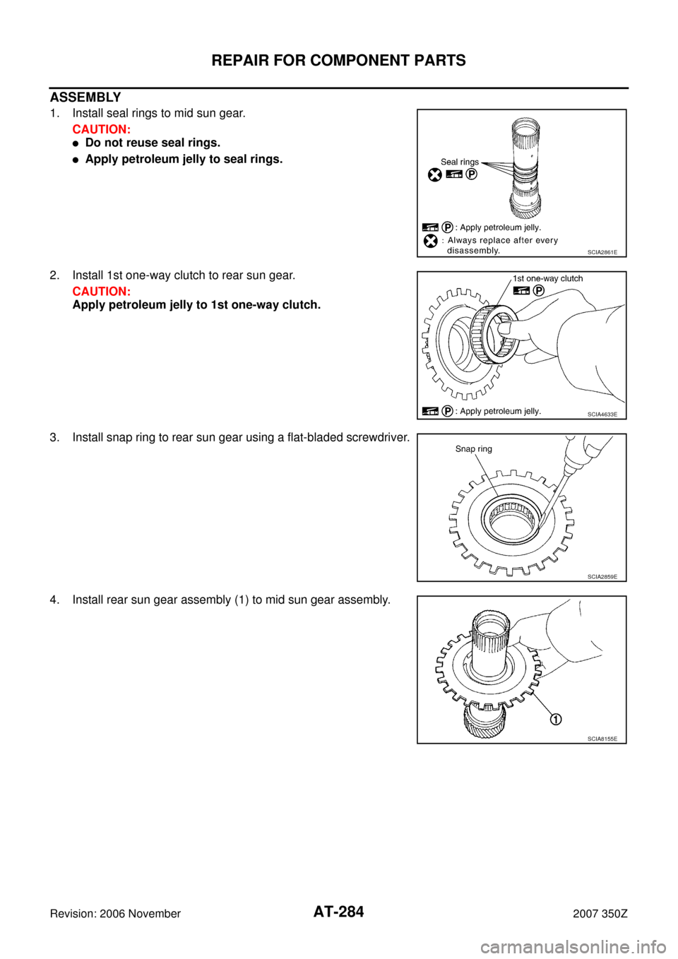
ASSEMBLY
1. Install seal rings to mid sun gear.
CAUTION:
�Do not reuse seal rings.
�Apply petroleum jelly to seal rings.
2. Install 1st one-way clutch to rear sun gear.
CAUTION:
Apply petroleum jelly to 1st one-way clutch.
3. Install snap ring to rear sun gear using a flat-bladed screwdriver.
4. Install rear sun gear assembly (1) to mid sun gear assembly.
SCIA2861E
SCIA4633E
SCIA2859E
SCIA8155E