2007 MITSUBISHI LANCER EVOLUTION check oil
[x] Cancel search: check oilPage 562 of 1449
MPI -Troubleshooting13A-30
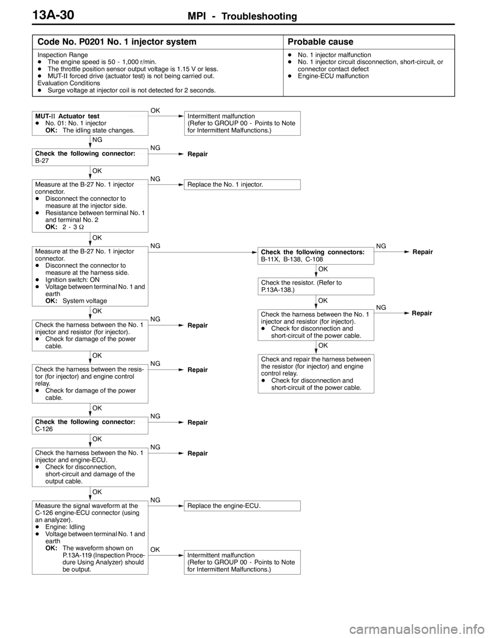
Code No. P0201 No. 1 injector systemProbable cause
Inspection Range
DThe engine speed is 50 - 1,000 r/min.
DThe throttle position sensor output voltage is 1.15 V or less.
DMUT-IIforced drive (actuator test) is not being carried out.
Evaluation Conditions
DSurge voltage at injector coil is not detected for 2 seconds.DNo. 1 injector malfunction
DNo. 1 injector circuit disconnection, short-circuit, or
connector contact defect
DEngine-ECU malfunction
OKIntermittent malfunction
(Refer to GROUP 00 - Points to Note
for Intermittent Malfunctions.)
OK
Measure the signal waveform at the
C-126 engine-ECU connector (using
an analyzer).
DEngine: Idling
DVoltage between terminal No. 1 and
earth
OK:The waveform shown on
P.13A-119 (Inspection Proce-
dure Using Analyzer) should
be output.NGReplace the engine-ECU.
OK
Check the harness between the No. 1
injector and engine-ECU.
DCheck for disconnection,
short-circuit and damage of the
output cable.NG
Repair
OK
Check the following connector:
C-126NG
Repair
OK
Check the harness between the resis-
tor (for injector) and engine control
relay.
DCheck for damage of the power
cable.NG
Repair
OK
Check the harness between the No. 1
injector and resistor (for injector).
DCheck for damage of the power
cable.NG
Repair
OK
Check and repair the harness between
the resistor (for injector) and engine
control relay.
DCheck for disconnection and
short-circuit of the power cable.NG
OK
Check the harness between the No. 1
injector and resistor (for injector).
DCheck for disconnection and
short-circuit of the power cable.Repair
OK
Check the resistor. (Refer to
P.13A-138.)
OK
Measure at the B-27 No. 1 injector
connector.
DDisconnect the connector to
measure at the harness side.
DIgnition switch: ON
DVoltage between terminal No. 1 and
earth
OK:System voltageNGCheck the following connectors:
B-11X, B-138, C-108NG
Repair
OK
Measure at the B-27 No. 1 injector
connector.
DDisconnect the connector to
measure at the injector side.
DResistance between terminal No. 1
and terminal No. 2
OK:2-3ΩNGReplace the No. 1 injector.
NG
Check the following connector:
B-27NG
Repair
MUT-IIActuator test
DNo. 01: No. 1 injector
OK:The idling state changes.OKIntermittent malfunction
(Refer to GROUP 00 - Points to Note
for Intermittent Malfunctions.)
Page 563 of 1449
MPI -Troubleshooting13A-31
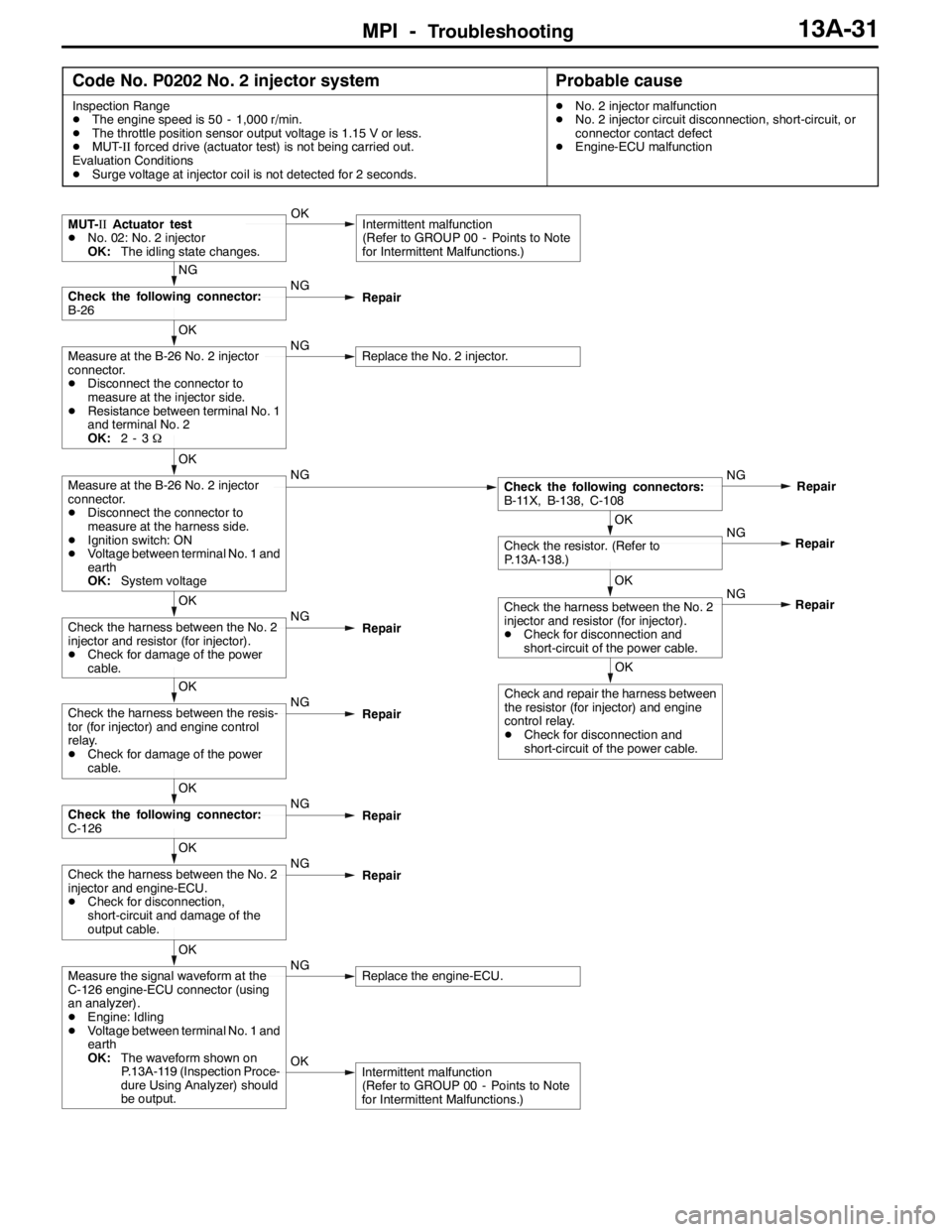
Code No. P0202 No. 2 injector systemProbable cause
Inspection Range
DThe engine speed is 50 - 1,000 r/min.
DThe throttle position sensor output voltage is 1.15 V or less.
DMUT-IIforced drive (actuator test) is not being carried out.
Evaluation Conditions
DSurge voltage at injector coil is not detected for 2 seconds.DNo. 2 injector malfunction
DNo. 2 injector circuit disconnection, short-circuit, or
connector contact defect
DEngine-ECU malfunction
OKIntermittent malfunction
(Refer to GROUP 00 - Points to Note
for Intermittent Malfunctions.)
OK
Measure the signal waveform at the
C-126 engine-ECU connector (using
an analyzer).
DEngine: Idling
DVoltage between terminal No. 1 and
earth
OK:The waveform shown on
P.13A-119 (Inspection Proce-
dure Using Analyzer) should
be output.NGReplace the engine-ECU.
OK
Check the harness between the No. 2
injector and engine-ECU.
DCheck for disconnection,
short-circuit and damage of the
output cable.NG
Repair
OK
Check the following connector:
C-126NG
Repair
OK
Check the harness between the resis-
tor (for injector) and engine control
relay.
DCheck for damage of the power
cable.NG
Repair
OK
Check and repair the harness between
the resistor (for injector) and engine
control relay.
DCheck for disconnection and
short-circuit of the power cable.NG
OK
Check the harness between the No. 2
injector and resistor (for injector).
DCheck for disconnection and
short-circuit of the power cable.Repair NG
OK
Check the resistor. (Refer to
P.13A-138.)Repair
OK
Check the harness between the No. 2
injector and resistor (for injector).
DCheck for damage of the power
cable.NG
Repair
OK
Measure at the B-26 No. 2 injector
connector.
DDisconnect the connector to
measure at the harness side.
DIgnition switch: ON
DVoltage between terminal No. 1 and
earth
OK:System voltageNGCheck the following connectors:
B-11X, B-138, C-108NG
Repair
OK
Measure at the B-26 No. 2 injector
connector.
DDisconnect the connector to
measure at the injector side.
DResistance between terminal No. 1
and terminal No. 2
OK:2-3ΩNGReplace the No. 2 injector.
NG
Check the following connector:
B-26NG
Repair
MUT-IIActuator test
DNo. 02: No. 2 injector
OK:The idling state changes.OKIntermittent malfunction
(Refer to GROUP 00 - Points to Note
for Intermittent Malfunctions.)
Page 564 of 1449
MPI -Troubleshooting13A-32
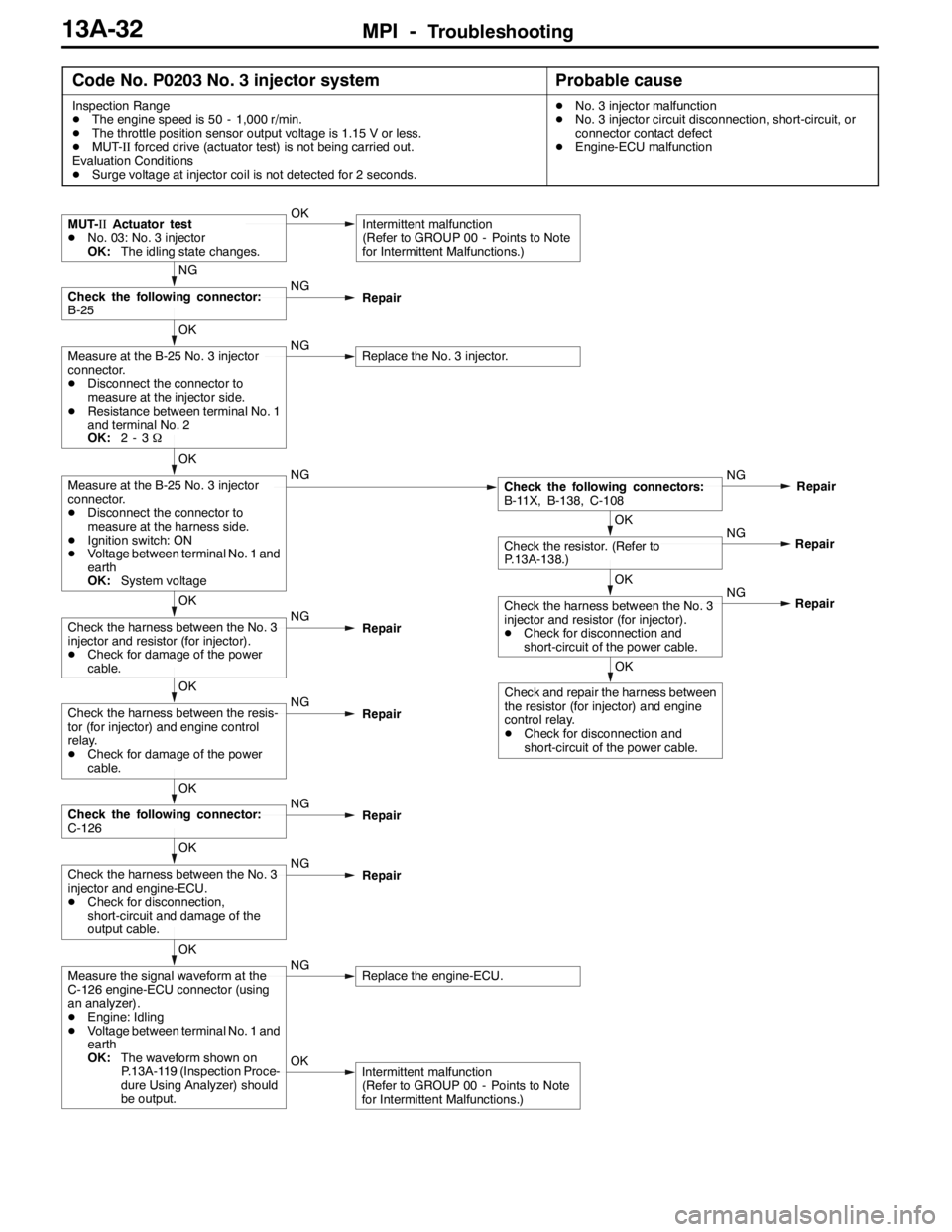
Code No. P0203 No. 3 injector systemProbable cause
Inspection Range
DThe engine speed is 50 - 1,000 r/min.
DThe throttle position sensor output voltage is 1.15 V or less.
DMUT-IIforced drive (actuator test) is not being carried out.
Evaluation Conditions
DSurge voltage at injector coil is not detected for 2 seconds.DNo. 3 injector malfunction
DNo. 3 injector circuit disconnection, short-circuit, or
connector contact defect
DEngine-ECU malfunction
OKIntermittent malfunction
(Refer to GROUP 00 - Points to Note
for Intermittent Malfunctions.)
OK
Measure the signal waveform at the
C-126 engine-ECU connector (using
an analyzer).
DEngine: Idling
DVoltage between terminal No. 1 and
earth
OK:The waveform shown on
P.13A-119 (Inspection Proce-
dure Using Analyzer) should
be output.NGReplace the engine-ECU.
OK
Check the harness between the No. 3
injector and engine-ECU.
DCheck for disconnection,
short-circuit and damage of the
output cable.NG
Repair
OK
Check the following connector:
C-126NG
Repair
OK
Check the harness between the resis-
tor (for injector) and engine control
relay.
DCheck for damage of the power
cable.NG
Repair
OK
Check and repair the harness between
the resistor (for injector) and engine
control relay.
DCheck for disconnection and
short-circuit of the power cable.NG
OK
Check the harness between the No. 3
injector and resistor (for injector).
DCheck for disconnection and
short-circuit of the power cable.Repair NG
OK
Check the resistor. (Refer to
P.13A-138.)Repair
OK
Check the harness between the No. 3
injector and resistor (for injector).
DCheck for damage of the power
cable.NG
Repair
OK
Measure at the B-25 No. 3 injector
connector.
DDisconnect the connector to
measure at the harness side.
DIgnition switch: ON
DVoltage between terminal No. 1 and
earth
OK:System voltageNGCheck the following connectors:
B-11X, B-138, C-108NG
Repair
OK
Measure at the B-25 No. 3 injector
connector.
DDisconnect the connector to
measure at the injector side.
DResistance between terminal No. 1
and terminal No. 2
OK:2-3ΩNGReplace the No. 3 injector.
NG
Check the following connector:
B-25NG
Repair
MUT-IIActuator test
DNo. 03: No. 3 injector
OK:The idling state changes.OKIntermittent malfunction
(Refer to GROUP 00 - Points to Note
for Intermittent Malfunctions.)
Page 565 of 1449
MPI -Troubleshooting13A-33
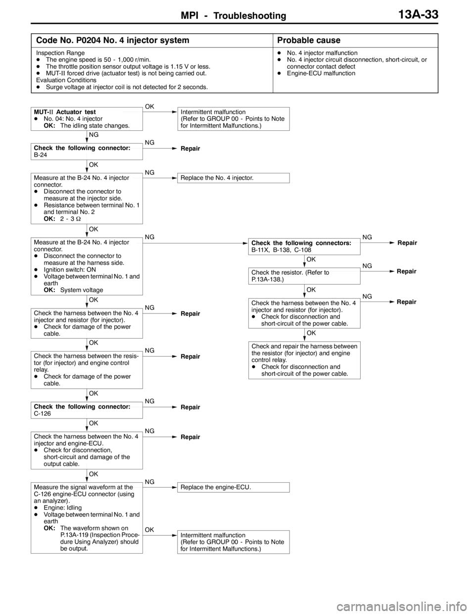
Code No. P0204 No. 4 injector systemProbable cause
Inspection Range
DThe engine speed is 50 - 1,000 r/min.
DThe throttle position sensor output voltage is 1.15 V or less.
DMUT-IIforced drive (actuator test) is not being carried out.
Evaluation Conditions
DSurge voltage at injector coil is not detected for 2 seconds.DNo. 4 injector malfunction
DNo. 4 injector circuit disconnection, short-circuit, or
connector contact defect
DEngine-ECU malfunction
OKIntermittent malfunction
(Refer to GROUP 00 - Points to Note
for Intermittent Malfunctions.)
OK
Measure the signal waveform at the
C-126 engine-ECU connector (using
an analyzer).
DEngine: Idling
DVoltage between terminal No. 1 and
earth
OK:The waveform shown on
P.13A-119 (Inspection Proce-
dure Using Analyzer) should
be output.NGReplace the engine-ECU.
OK
Check the harness between the No. 4
injector and engine-ECU.
DCheck for disconnection,
short-circuit and damage of the
output cable.NG
Repair
OK
Check the following connector:
C-126NG
Repair
OK
Check the harness between the resis-
tor (for injector) and engine control
relay.
DCheck for damage of the power
cable.NG
Repair
OK
Check and repair the harness between
the resistor (for injector) and engine
control relay.
DCheck for disconnection and
short-circuit of the power cable.NG
OK
Check the harness between the No. 4
injector and resistor (for injector).
DCheck for disconnection and
short-circuit of the power cable.Repair NG
OK
Check the resistor. (Refer to
P.13A-138.)Repair
OK
Check the harness between the No. 4
injector and resistor (for injector).
DCheck for damage of the power
cable.NG
Repair
OK
Measure at the B-24 No. 4 injector
connector.
DDisconnect the connector to
measure at the harness side.
DIgnition switch: ON
DVoltage between terminal No. 1 and
earth
OK:System voltageNGCheck the following connectors:
B-11X, B-138, C-108NG
Repair
OK
Measure at the B-24 No. 4 injector
connector.
DDisconnect the connector to
measure at the injector side.
DResistance between terminal No. 1
and terminal No. 2
OK:2-3ΩNGReplace the No. 4 injector.
NG
Check the following connector:
B-24NG
Repair
MUT-IIActuator test
DNo. 04: No. 4 injector
OK:The idling state changes.OKIntermittent malfunction
(Refer to GROUP 00 - Points to Note
for Intermittent Malfunctions.)
Page 571 of 1449
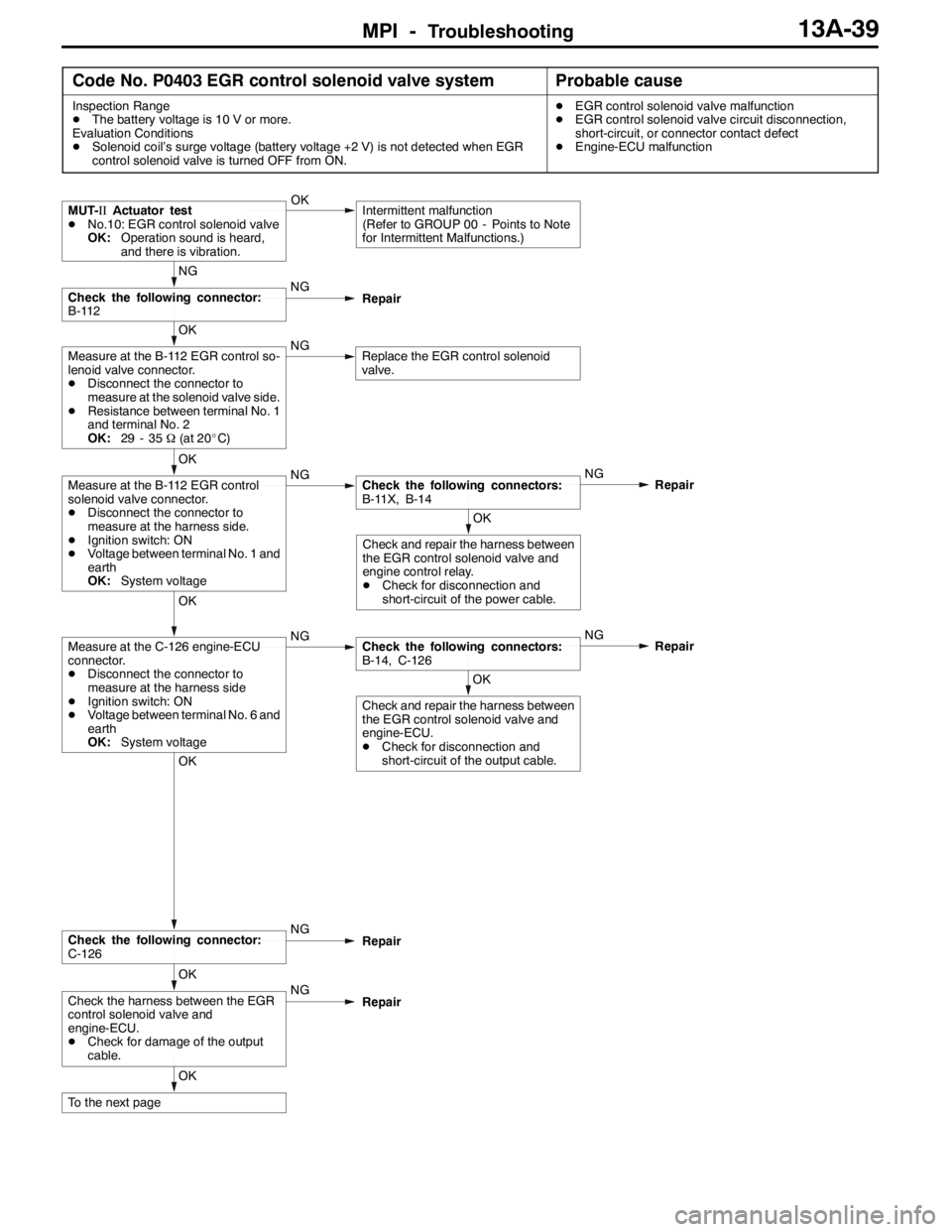
MPI -Troubleshooting13A-39
Code No. P0403 EGR control solenoid valve systemProbable cause
Inspection Range
DThe battery voltage is 10 V or more.
Evaluation Conditions
DSolenoid coil’s surge voltage (battery voltage +2 V) is not detected when EGR
control solenoid valve is turned OFF from ON.DEGR control solenoid valve malfunction
DEGR control solenoid valve circuit disconnection,
short-circuit, or connector contact defect
DEngine-ECU malfunction
OK
To the next page
OK
Check the harness between the EGR
control solenoid valve and
engine-ECU.
DCheck for damage of the output
cable.NG
Repair
OK
Check the following connector:
C-126NG
Repair
OK
Check and repair the harness between
the EGR control solenoid valve and
engine-ECU.
DCheck for disconnection and
short-circuit of the output cable.
OK
Measure at the C-126 engine-ECU
connector.
DDisconnect the connector to
measure at the harness side
DIgnition switch: ON
DVoltage between terminal No. 6 and
earth
OK:System voltageNGCheck the following connectors:
B-14, C-126NG
Repair
OK
Check and repair the harness between
the EGR control solenoid valve and
engine control relay.
DCheck for disconnection and
short-circuit of the power cable.
OK
Measure at the B-112 EGR control
solenoid valve connector.
DDisconnect the connector to
measure at the harness side.
DIgnition switch: ON
DVoltage between terminal No. 1 and
earth
OK:System voltageNGCheck the following connectors:
B-11X, B-14NG
Repair
OK
Measure at the B-112 EGR control so-
lenoid valve connector.
DDisconnect the connector to
measure at the solenoid valve side.
DResistance between terminal No. 1
and terminal No. 2
OK:29 - 35Ω(at 20_C)NGReplace the EGR control solenoid
valve.
NG
Check the following connector:
B-112NG
Repair
MUT-IIActuator test
DNo.10: EGR control solenoid valve
OK:Operation sound is heard,
and there is vibration.OKIntermittent malfunction
(Refer to GROUP 00 - Points to Note
for Intermittent Malfunctions.)
Page 573 of 1449
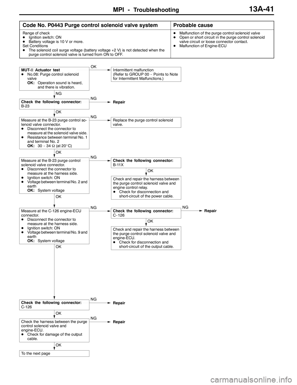
MPI -Troubleshooting13A-41
Code No. P0443 Purge control solenoid valve systemProbable cause
Range of check
DIgnition switch: ON
DBattery voltage is 10 V or more.
Set Conditions
DThe solenoid coil surge voltage (battery voltage +2 V) is not detected when the
purge control solenoid valve is turned from ON to OFF.DMalfunction of the purge control solenoid valve
DOpen or short circuit in the purge control solenoid
valve circuit or loose connector contact.
DMalfunction of Engine-ECU
OK
To the next page
OK
Check the harness between the purge
control solenoid valve and
engine-ECU.
DCheck for damage of the output
cable.NG
Repair
OK
Check the following connector:
C-126NG
Repair
OK
Check and repair the harness between
the purge control solenoid valve and
engine-ECU.
DCheck for disconnection and
short-circuit of the output cable.
OK
Measure at the C-126 engine-ECU
connector.
DDisconnect the connector to
measure at the harness side.
DIgnition switch: ON
DVoltage between terminal No. 9 and
earth
OK:System voltageNGCheck the following connector:
C - 126NG
Repair
OK
Check and repair the harness between
the purge control solenoid valve and
engine control relay.
DCheck for disconnection and
short-circuit of the power cable.
OK
Measure at the B-23 purge control
solenoid valve connector.
DDisconnect the connector to
measure at the harness side.
DIgnition switch: ON
DVoltage between terminal No. 2 and
earth
OK:System voltageNGCheck the following connector:
B-11X
OK
Measure at the B-23 purge control so-
lenoid valve connector.
DDisconnect the connector to
measure at the solenoid valve side.
DResistance between terminal No. 1
and terminal No. 2
OK:30 - 34Ω(at 20_C)NGReplace the purge control solenoid
valve.
NG
Check the following connector:
B-23NG
Repair
MUT-IIActuator test
DNo.08: Purge control solenoid
valve
OK:Operation sound is heard,
and there is vibration.OKIntermittent malfunction
(Refer to GROUP 00 - Points to Note
for Intermittent Malfunctions.)
Page 579 of 1449
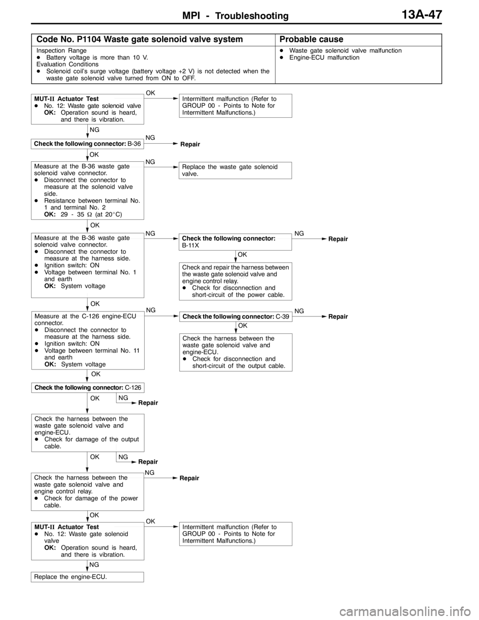
MPI -Troubleshooting13A-47
Code No. P1104 Waste gate solenoid valve systemProbable cause
Inspection Range
DBattery voltage is more than 10 V.
Evaluation Conditions
DSolenoid coil’s surge voltage (battery voltage +2 V) is not detected when the
waste gate solenoid valve turned from ON to OFF.DWaste gate solenoid valve malfunction
DEngine-ECU malfunction
OK
NG
Replace the engine-ECU.
OKIntermittent malfunction (Refer to
GROUP 00 - Points to Note for
Intermittent Malfunctions.)MUT-IIActuator Test
DNo. 12: Waste gate solenoid
valve
OK:Operation sound is heard,
and there is vibration.OKNG
Repair
OK
NG
Intermittent malfunction (Refer to
GROUP 00 - Points to Note for
Intermittent Malfunctions.)
OK
Check the following connector:B-36
MUT-IIActuator Test
DNo. 12: Waste gate solenoid valve
OK:Operation sound is heard,
and there is vibration.
NG
Repair
NGNG
Repair
OK
Check the harness between the
waste gate solenoid valve and
engine-ECU.
DCheck for disconnection and
short-circuit of the output cable.
Check the following connector:C-39
OK
Check the following connector:C-126
Measure at the C-126 engine-ECU
connector.
DDisconnect the connector to
measure at the harness side.
DIgnition switch: ON
DVoltage between terminal No. 11
and earth
OK:System voltageNG
Replace the waste gate solenoid
valve.Measure at the B-36 waste gate
solenoid valve connector.
DDisconnect the connector to
measure at the solenoid valve
side.
DResistance between terminal No.
1 and terminal No. 2
OK:29 - 35Ω(at 20_C)
OK
NG
Measure at the B-36 waste gate
solenoid valve connector.
DDisconnect the connector to
measure at the harness side.
DIgnition switch: ON
DVoltage between terminal No. 1
and earth
OK:System voltage
OKNG
Repair
OK
OK
Check and repair the harness between
the waste gate solenoid valve and
engine control relay.
DCheck for disconnection and
short-circuit of the power cable.
Check the following connector:
B-11X
NG
RepairCheck the harness between the
waste gate solenoid valve and
engine control relay.
DCheck for damage of the power
cable.NG
Repair
OK
Check the harness between the
waste gate solenoid valve and
engine-ECU.
DCheck for damage of the output
cable.
Page 580 of 1449
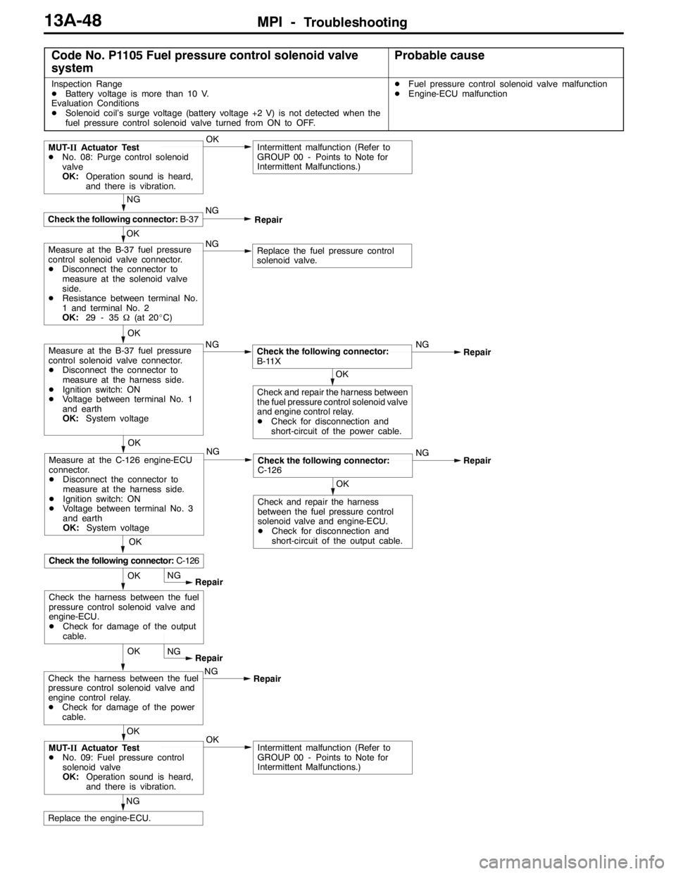
MPI -Troubleshooting13A-48
Code No. P1105 Fuel pressure control solenoid valve
systemProbable cause
Inspection Range
DBattery voltage is more than 10 V.
Evaluation Conditions
DSolenoid coil’s surge voltage (battery voltage +2 V) is not detected when the
fuel pressure control solenoid valve turned from ON to OFF.DFuel pressure control solenoid valve malfunction
DEngine-ECU malfunction
OK
NG
Replace the engine-ECU.
OKIntermittent malfunction (Refer to
GROUP 00 - Points to Note for
Intermittent Malfunctions.)MUT-IIActuator Test
DNo. 09: Fuel pressure control
solenoid valve
OK:Operation sound is heard,
and there is vibration.OKNG
Repair
OK
NG
Intermittent malfunction (Refer to
GROUP 00 - Points to Note for
Intermittent Malfunctions.)
OK
Check the following connector:B-37
MUT-IIActuator Test
DNo. 08: Purge control solenoid
valve
OK:Operation sound is heard,
and there is vibration.
NG
Repair
NGNG
Repair
OK
OK
Check and repair the harness
between the fuel pressure control
solenoid valve and engine-ECU.
DCheck for disconnection and
short-circuit of the output cable.
Check the following connector:
C-126
OK
Check the following connector:C-126
Measure at the C-126 engine-ECU
connector.
DDisconnect the connector to
measure at the harness side.
DIgnition switch: ON
DVoltage between terminal No. 3
and earth
OK:System voltageNG
Replace the fuel pressure control
solenoid valve.Measure at the B-37 fuel pressure
control solenoid valve connector.
DDisconnect the connector to
measure at the solenoid valve
side.
DResistance between terminal No.
1 and terminal No. 2
OK:29 - 35Ω(at 20_C)
OK
NG
Measure at the B-37 fuel pressure
control solenoid valve connector.
DDisconnect the connector to
measure at the harness side.
DIgnition switch: ON
DVoltage between terminal No. 1
and earth
OK:System voltage
OKNG
Repair
OK
OKCheck and repair the harness between
the fuel pressure control solenoid valve
and engine control relay.
DCheck for disconnection and
short-circuit of the power cable.
Check the following connector:
B-11X
NG
RepairCheck the harness between the fuel
pressure control solenoid valve and
engine control relay.
DCheck for damage of the power
cable.NG
Repair
OK
Check the harness between the fuel
pressure control solenoid valve and
engine-ECU.
DCheck for damage of the output
cable.