Page 1056 of 1449

BASIC BRAKE SYSTEM -On-vehicle Service35A-14
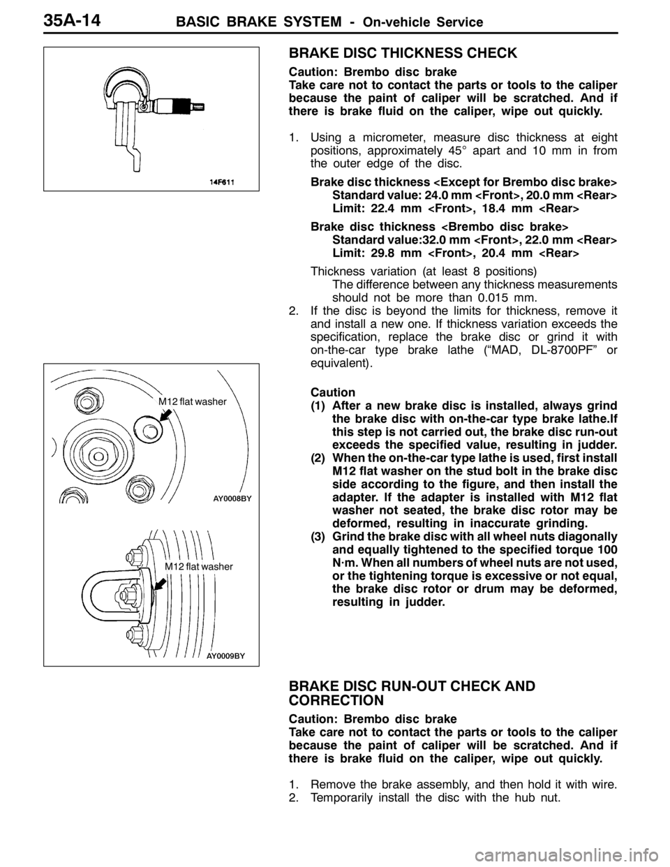
BRAKE DISC THICKNESS CHECK
Caution: Brembo disc brake
Take care not to contact the parts or tools to the caliper
because the paint of caliper will be scratched. And if
there is brake fluid on the caliper, wipe out quickly.
1. Using a micrometer, measure disc thickness at eight
positions, approximately 45°apart and 10 mm in from
the outer edge of the disc.
Brake disc thickness
Standard value: 24.0 mm , 20.0 mm
Limit: 22.4 mm , 18.4 mm
Brake disc thickness
Standard value:32.0 mm , 22.0 mm
Limit: 29.8 mm , 20.4 mm
Thickness variation (at least 8 positions)
The difference between any thickness measurements
should not be more than 0.015 mm.
2. If the disc is beyond the limits for thickness, remove it
and install a new one. If thickness variation exceeds the
specification, replace the brake disc or grind it with
on-the-car type brake lathe (“MAD, DL-8700PF” or
equivalent).
Caution
(1) After a new brake disc is installed, always grind
the brake disc with on-the-car type brake lathe.If
this step is not carried out, the brake disc run-out
exceeds the specified value, resulting in judder.
(2) When the on-the-car type lathe is used, first install
M12 flat washer on the stud bolt in the brake disc
side according to the figure, and then install the
adapter. If the adapter is installed with M12 flat
washer not seated, the brake disc rotor may be
deformed, resulting in inaccurate grinding.
(3) Grind the brake disc with all wheel nuts diagonally
and equally tightened to the specified torque 100
N·m. When all numbers of wheel nuts are not used,
or the tightening torque is excessive or not equal,
the brake disc rotor or drum may be deformed,
resulting in judder.
BRAKE DISC RUN-OUT CHECK AND
CORRECTION
Caution: Brembo disc brake
Take care not to contact the parts or tools to the caliper
because the paint of caliper will be scratched. And if
there is brake fluid on the caliper, wipe out quickly.
1. Remove the brake assembly, and then hold it with wire.
2. Temporarily install the disc with the hub nut.
M12 flat washer
M12 flat washer
Page 1059 of 1449

BASIC BRAKE SYSTEM -Brake Pedal/Proportioning Valve,
Master Cylinder and Brake Booster35A-17
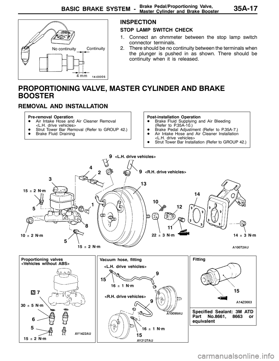
INSPECTION
STOP LAMP SWITCH CHECK
1. Connect an ohmmeter between the stop lamp switch
connector terminals.
2. There should be no continuity between the terminals when
the plunger is pushed in as shown. There should be
continuity when it is released.
PROPORTIONING VALVE, MASTER CYLINDER AND BRAKE
BOOSTER
REMOVAL AND INSTALLATION
Pre-removal Operation
DAir Intake Hose and Air Cleaner Removal
DStrut Tower Bar Removal (Refer to GROUP 42.)
DBrake Fluid DrainingPost-installation Operation
DBrake Fluid Supplying and Air Bleeding
(Refer to P.35A-10.)
DBrake Pedal Adjustment (Refer to P.35A-7.)
DAir Intake Hose and Air Cleaner Installation
DStrut Tower Bar Installation (Refer to GROUP 42.)
510
11 3
12 4
14
15±2N·m 15±2N·m
22±3N·m
10±2N·m
13 2
8
14±3N·m
519
9
15±2N·m
5
Proportioning valves
67
30±5N·m
9
15
16±1N·m
9
15
16±1N·m
Vacuum hose, fitting
Specified Sealant: 3M ATD
Part No.8661, 8663 or
equivalent
15
Fitting
4mm
No continuityContinuity
Page 1060 of 1449

BASIC BRAKE SYSTEM -ProportioningValve,MasterCylinder
and Brake Booster35A-18
Master cylinder removal steps
1. Clutch hose connection
2. Brake fluid level sensor connector
3. Reservoir cap assembly
4. Brake fluid level sensor
5. Brake pipe connection
6. Proportioning valve
7. O ring
8. Master cylinder
Proportioning valve removal steps
5. Brake pipe connection
6. Proportioning valve
7. O ring
Brake booster removal steps
1. Clutch hose connection
2. Brake fluid level sensor connector5. Brake pipe connection
8. Master cylinder
"BADPush rod protrusion amount check and
adjustment
"AA9. Vacuum hose
(With built-in check valve)
10. Snap pin
11. Pin assembly
12. Clevis
DRemove A/C liquid pipe B
from the
retaining clip.(Refer to GROUP 55A
- Refrigerant Line.)
13. Brake booster
14. Sealer
Fitting removal steps
"AA9. Vacuum hose
(With built-in check valve)
15. Fitting
INSTALLATION SERVICE POINTS
"AAVACUUM HOSE CONNECTION
Insert the vacuum hose to the brake booster with its paint
mark facing upward, and then secure the hose by using the
hose clip.
"BAPUSH ROD PROTRUSION AMOUNT CHECK AND
ADJUSTMENT
1. Measure dimension (A).
Standard value (A) : 8.98 - 9.23 mm
NOTE
When a negative pressure of 66.7 kPa is applied to the
brake booster, the push rod should protrude 10.27 – 10.53
mm.
Block gauge Measuring distance A
A
Page 1061 of 1449
BASIC BRAKE SYSTEM -ProportioningValve,MasterCylinder
and Brake BoosterBASIC BRAKE SYSTEM -ProportioningValve,MasterCylinder
and Brake Booster35A-19
2. If the protrusion amount is not within the standard value
range, adjust the push rod length by turning the push
rod. Use the special tool to turn the push rod while holding
the rod spline with angle-nose pliers.
MASTER CYLINDER
DISASSEMBLY AND REASSEMBLY
1
2
3838
Brake fluid: DOT3 or DOT4
77
5Master cylinder kit
4
9
6
10
9
8
9
10
Disassembly steps
1. Reservoir cap
2. Filter
3. Spring pin
4. Reservoir tank
5. Reservoir seal6. Pin
7. Piston retainer
8. Primary piston assembly
9. Secondary piston assembly
10. Master cylinder body
Angle-nose pliers
MB991568
Rod spline
Page 1062 of 1449
BASIC BRAKE SYSTEM -Disc Brake35A-20
DISC BRAKE
REMOVAL AND INSTALLATION
Caution
If the vehicle is equipped with the Brembo disc brake, during maintenance, take care not to contact
the parts or tools to the caliper because the paint of caliper will be scratched. And if there is
brake fluid on the caliper, wipe out quickly.
Pre-removal Operation
Brake Fluid DrainingPost-installation Operation
Brake Fluid Supplying and Air Bleeding
(Refer to P.35A-10.)
34
21
100±10 N·m
108±10 N·m
30±5 N·m
3 2 1
54±5 N·m
15±2 N·m
4
Removal steps
1. Brake hose connection
2. Gasket
"AA3. Disc brake assembly
4. Brake disc
Page 1065 of 1449
BASIC BRAKE SYSTEM -Disc Brake35A-23
Front
Caution
Take care not to contact the parts or tools to the caliper because the paint of caliper will be scratched.
And if there is brake fluid on the caliper, wipe out quickly.
9
4 1
2 4
56
8
9
Brake caliper kit
Pad set Seal and boot kit
55
2
3 1 10
87
6
3 9
9 7
Clip setShim set
6
106 3
7 5
7
2 1 2
1
4
Grease: Repair kit grease
14±2 N·m
Disassembly steps
1. Pin
2. Cross spring
3. Pad and wear indicator assembly
4. Pad assembly
5. Shim6. Air bleeder screw
AA"7. Piston boot
AA"8. Piston
AB"9. Piston seal
10. Caliper body
Page 1067 of 1449
BASIC BRAKE SYSTEM -Disc Brake35A-25
Rear
Caution
Take care not to contact the parts or tools to the caliper because the paint of caliper will be scratched.
And if there is brake fluid on the caliper, wipe out quickly.
9
4 1 24
5 6
8
9
Brake caliper kit
Pad set Seal and boot kit
5
5 2
3 1 10
876
3 9
9 7
Clip setShim set
6 10 63
7 5
7
21 2 14
Grease: Repair kit grease
14±2 N·m
Disassembly steps
1. Pin
2. Cross spring
3. Pad and wear indicator assembly
4. Pad assembly
5. Shim6. Air bleeder screw
AA"7. Piston boot
AA"8. Piston
AB"9. Piston seal
10. Caliper body
Page 1068 of 1449
BASIC BRAKE SYSTEM -Disc Brake35A-26
LUBRICATION POINTS
Piston seal
Grease: Repair kit grease
Caution
The piston seal inside the
seal and boot kit is coated
with special grease, so do
not wipe this grease off.
Brake fluid: DOT3 or DOT4
Grease: Repair kit greaseGrease: Repair kit grease