Page 799 of 1449
CLUTCH -Clutch Control21A-9
DISASSEMBLY AND REASSEMBLY
CLUTCH MASTER CYLINDER
Caution
Do not disassemble piston assembly.
1
4 5
27
223
4
Grease: Rubber grease
Clutch fluid:
Brake fluid DOT3 or DOT4
Piston repair kit
13±2 N·m
12
3
6
8
4 5
8
Disassembly steps
1. Piston stopper ring
2. Piston assembly
"AA3. Push rod assembly
4. Boot5. Spring pin
6. Reservoir tank
7. Seal
8. Master cylinder body
INSTALLATION SERVICE POINT
"AAPUSH ROD ASSEMBLY INSTALLATION
Set the length of the push rod assembly to the shown
dimension to make the adjustment of clutch pedal easier.
104.3±0.5 mm
Page 802 of 1449

CLUTCH OVERHAUL -General Description/Specifications/Service Specifications/
Tightening Torque/Lubricants21B-2
GENERAL DESCRIPTION
The pull-type clutch has been adopted to improve the cut-off at high rotations and reduce the clutch
pedal pressing force.
SPECIFICATIONS
Clutch discTypeDry single-disc type
Facing dimension mm240×160
Clutch coverTypeDiaphragm spring, pull-type
Set load N9,320
Clutch control methodHydraulic method
SERVICE SPECIFICATIONS
ItemsLimit value mm
Clutch disc facing rivet sink0.3
Clearance between release cylinder inner diameter and
piston outer diameter0.15
TIGHTENING TORQUE
ItemsTorque N•m
Clutch tube flare nut15±2
Clutch fluid line bracket mounting bolt18±3
Clutch release cylinder air breather11±1
Clutch release cylinder mounting bolt18±3
Clutch release fork shaft mounting bolt9.8±2
Clutch release cylinder union bolt22±2
LUBRICANTS
ItemsSpecified lubricants
Release fork and release cylinder push rod contact sectionMITSUBISHI genuine grease Part No.0101011
orequivalent
Release fork and release fork shaft sliding section
or equivalent
Release fork and release bearing contact section
Piston and piston cup circumferenceMITSUBISHI genuine brake fluid
“
DIA QUEENBRAKEFLUIDSUPER4”
Release cylinder inner circumference
“DIA-QUEENBRAKEFLUIDSUPER4”
or equivalent
Page 807 of 1449
CLUTCH OVERHAUL -Clutch Release Cylinder21B-7
REASSEMBLY SERVICE POINT
"AAPISTON/PISTON CUP INSTALLATION
After applying brake fluid on the inner surface of the release
cylinder and circumference of the piston and piston cup, insert
the piston and piston cup into the release cylinder.
Brake fluid
Specified fluid:
MITSUBISHI genuine brake fluid “DIA-QUEEN
BRAKE FLUID SUPER 4” or equivalent
INSEPCTION
RELEASE CYLINDER
(1) Check the inner surface of the release cylinder for rust
and damage.
(2) Using a cylinder gauge, measure the inner diameter of
the release cylinder at approx. three positions (deepest
section, middle, opening). If the clearance with the outer
diameter of the piston exceeds the limit value, replace
the release cylinder assembly.
Limit value: 0.15 mm
Piston cup Piston
Page 852 of 1449

MANUAL TRANSMISSION - On-vehicle Service22A-44
(2) If the hydraulic unit function has been stopped by
fail-safe, the hydraulic unit cannot be forcibly driven.
6. Check that the generated oil pressure of the hydraulic
unit satisfies the standard value.
Standard value: 1.0 – 1.6 MPa
Caution
While the oil pressure is checked, add fluid as
necessary to ensure that it is left in the oil reservoir
during the entire procedure.
7. If the measured value exceeds the standard value, replace
the hydraulic unit.
8. Connect the hydraulic unit and transfer connector
assembly, and tighten the flare nut at the specified torque.
Tightening torque: 34±5 N·m (when screw is dry)
26±4 N·m (when screw is applied with oil)
9. Supply the specified fluid up to the MAX level of the
oil reservoir, and bleed the oil pressure pipes.
Specified fluid: DIA QUEEN ATF SP III
Quantity:
0.9 dm
3
1.0 dm3
WHEEL SPEED SENSOR OUTPUT VOLTAGE
MEASUREMENT
(VEHICLES WITHOUT AYC)>
1. Lift the vehicle, and release the parking brake.
2. Disconnect the 4WD-ECU connector, and measure at
the connector of the harness.
Caution
Insert the probe from the harness of the connector.
Inserting in the terminal side may cause contact fault.
3. Rotate the measured wheel by about 1/2 to 1
rotations/second, and check the output voltage between
the following terminals using a circuit tester (AC mV range)
or oscilloscope.
Terminal No.
Front leftFront rightRear leftRear right
6987
19222120
Page 934 of 1449

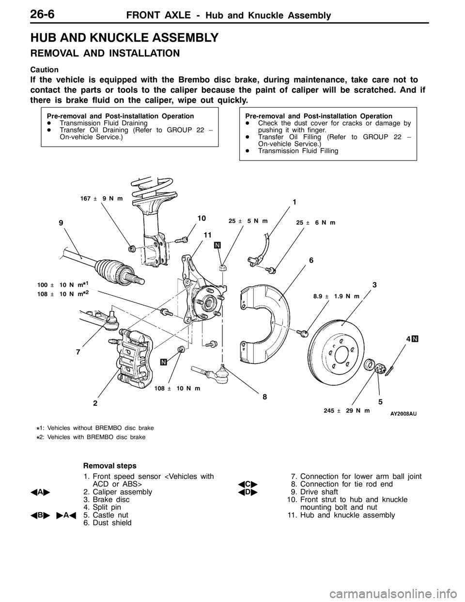
FRONT AXLE -Hub and Knuckle Assembly26-6
HUB AND KNUCKLE ASSEMBLY
REMOVAL AND INSTALLATION
Caution
If the vehicle is equipped with the Brembo disc brake, during maintenance, take care not to
contact the parts or tools to the caliper because the paint of caliper will be scratched. And if
there is brake fluid on the caliper, wipe out quickly.
Pre-removal and Post-installation Operation
DTransmission Fluid Draining
DTransfer Oil Draining (Refer to GROUP 22 –
On-vehicle Service.)Pre-removal and Post-installation Operation
DCheck the dust cover for cracks or damage by
pushing it with finger.
DTransfer Oil Filling (Refer to GROUP 22 –
On-vehicle Service.)
DTransmission Fluid Filling
25�¶5N��m
1
245�¶29 N��m
58
3
4
2
108�¶10 N��m
10
11
25�¶6N��m
6
9
100�¶10 N��m*1
108�¶10 N��m*2
167�¶9N��m
8.9�¶1.9 N��m
*1: Vehicles without BREMBO disc brake
*2: Vehicles with BREMBO disc brake
7
Removal steps
1. Front speed sensor
ACD or ABS>
AA"2. Caliper assembly
3. Brake disc
4. Split pin
AB""AA5. Castle nut
6. Dust shield7. Connection for lower arm ball joint
AC"8. Connection for tie rod end
AD"9. Drive shaft
10. Front strut to hub and knuckle
mounting bolt and nut
11. Hub and knuckle assembly
Page 935 of 1449

FRONT AXLE -Hub and Knuckle Assembly26-7
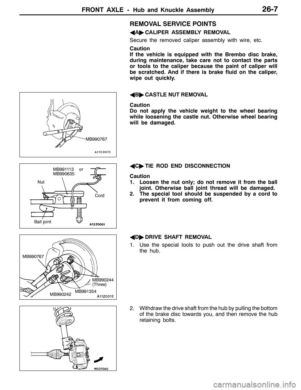
REMOVAL SERVICE POINTS
AA"CALIPER ASSEMBLY REMOVAL
Secure the removed caliper assembly with wire, etc.
Caution
If the vehicle is equipped with the Brembo disc brake,
during maintenance, take care not to contact the parts
or tools to the caliper because the paint of caliper will
be scratched. And if there is brake fluid on the caliper,
wipe out quickly.
AB"CASTLE NUT REMOVAL
Caution
Do not apply the vehicle weight to the wheel bearing
while loosening the castle nut. Otherwise wheel bearing
will be damaged.
AC"TIE ROD END DISCONNECTION
Caution
1. Loosen the nut only; do not remove it from the ball
joint. Otherwise ball joint thread will be damaged.
2. The special tool should be suspended by a cord to
prevent it from coming off.
AD"DRIVE SHAFT REMOVAL
1. Use the special tools to push out the drive shaft from
the hub.
2. Withdraw the drive shaft from the hub by pulling the bottom
of the brake disc towards you, and then remove the hub
retaining bolts.
MB990767
Nut
Cord
Ball joint
MB991113 or
MB990635
MB990242 MB990767MB991354
MB990244
(Three)
Page 938 of 1449

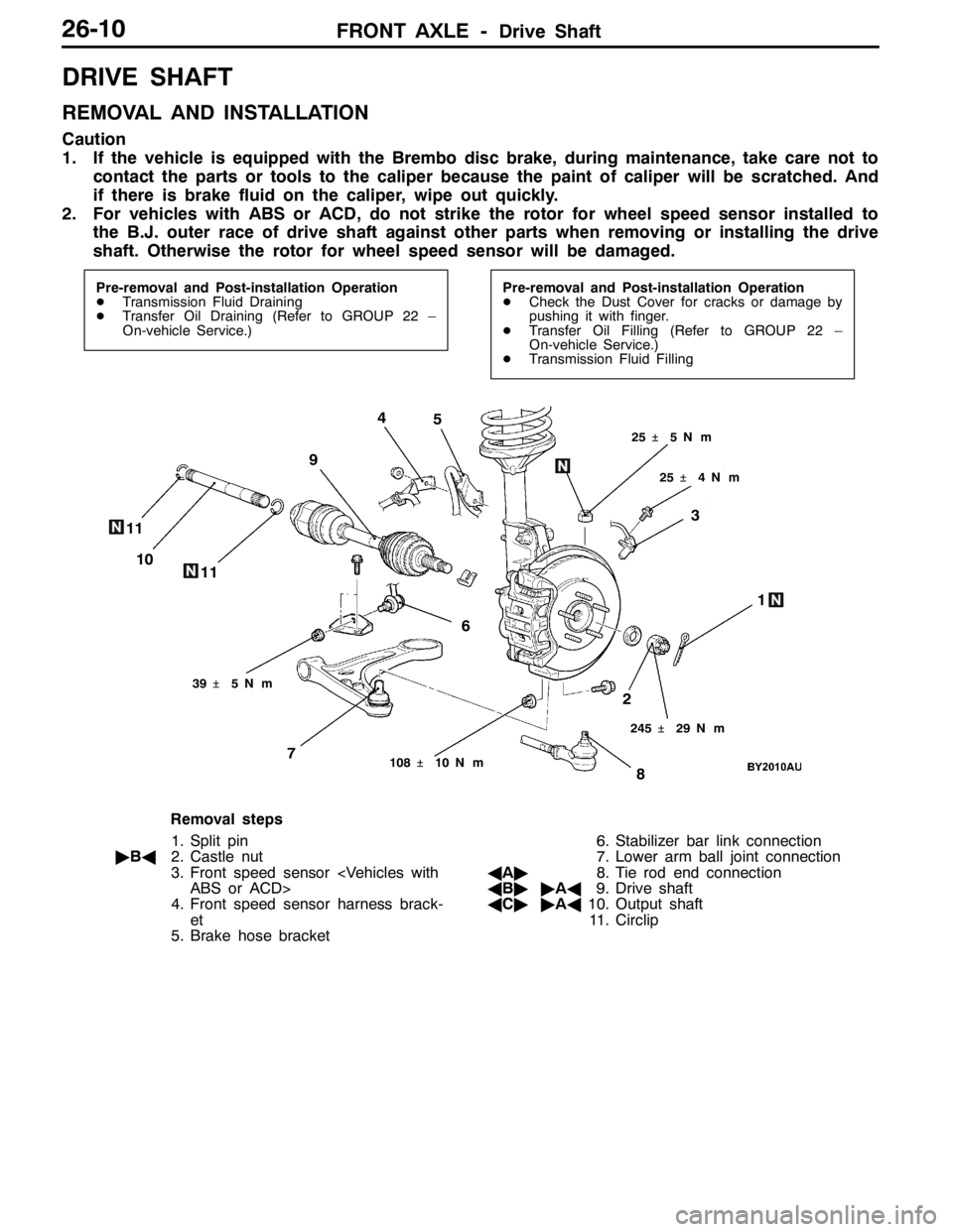
FRONT AXLE -Drive Shaft26-10
DRIVE SHAFT
REMOVAL AND INSTALLATION
Caution
1. If the vehicle is equipped with the Brembo disc brake, during maintenance, take care not to
contact the parts or tools to the caliper because the paint of caliper will be scratched. And
if there is brake fluid on the caliper, wipe out quickly.
2. For vehicles with ABS or ACD, do not strike the rotor for wheel speed sensor installed to
the B.J. outer race of drive shaft against other parts when removing or installing the drive
shaft. Otherwise the rotor for wheel speed sensor will be damaged.
Pre-removal and Post-installation Operation
DTransmission Fluid Draining
DTransfer Oil Draining (Refer to GROUP 22 –
On-vehicle Service.)Pre-removal and Post-installation Operation
DCheck the Dust Cover for cracks or damage by
pushing it with finger.
DTransfer Oil Filling (Refer to GROUP 22 –
On-vehicle Service.)
DTransmission Fluid Filling
1
6 9
8 5
74
3
2 11
25�¶4N��m 25�¶5N��m
245�¶29 N��m
108�¶10 N��m
10
11
39�¶5N��m
Removal steps
1. Split pin
"BA2. Castle nut
3. Front speed sensor
ABS or ACD>
4. Front speed sensor harness brack-
et
5. Brake hose bracket6. Stabilizer bar link connection
7. Lower arm ball joint connection
AA"8. Tie rod end connection
AB""AA9. Drive shaft
AC""AA10. Output shaft
11. Circlip
Page 968 of 1449

REAR AXLE -On-vehicle Service27B-22
8. If the measured value exceeds the standard value, replace
the hydraulic unit.
9. Connect the hydraulic unit and the hydraulic unit hose
assembly, and connect the torque transfer differential and
hydraulic unit hose assembly, tighten the flare nut in
specified torque.
Tightening torque: 34±5 N·m (Thread is not lubricated)
26±4 N·m (Thread is lubricated)
10. Supply the specified fluid up to the MAX level of the
oil reservoir, and bleed.
Specified fluid: ATF-SP III
Quantity: 1 L
WHEEL BEARING AXIAL PLAY CHECK
1. Remove the brake caliper and brake disc.
2. Check the bearing’s axial play.
Place a dial gauge against the hub surface; then move
the hub in the axial direction and check whether or not
there is axial play.
Limit: 0.05 mm
3. If the axial play exceeds the limit, the castle nut should
be tightened to the specified torque 225±25 N·m and
check the axial play again.
4. Replace the rear hub assembly if an adjustment cannot
be made to within the limit.
WHEEL BEARING ROTARY-SLIDING
RESISTANCE CHECK
1. Remove the brake caliper and brake disc.
2. After turning the hub a few times to seat the bearing,
wind a rope around the hub bolt and turn the hub by
pulling at a 90_angle with a spring balance. Measure
to determine whether or not the rotary-sliding resistance
of the rear hub is at the limit value.
Limit: 22 N or less