2007 MITSUBISHI LANCER EVOLUTION Engine diagram
[x] Cancel search: Engine diagramPage 382 of 1449

GENERAL -How to Use This Manual00-4
EXPLANATION OF MANUAL CONTENTS
Indicates procedures to be performed
before the work in that section is started,
and procedures to be performed after
the work in that section is finished.
Indicates (by symbols) where lubrica-
tion is necessary.
Maintenance and Servicing Procedures
The numbers provided within the diagram indi-
cate the sequence for maintenance and servic-
ing procedures.
DRemoval steps:
The part designation number corresponds
to the number in the illustration to indicate
removal steps.
DDisassembly steps:
The part designation number corresponds
to the number in the illustration to indicate
disassembly steps.DInstallation steps:
Specified in case installation is impossible
in reverse order of removal steps. Omitted
if installation is possible in reverse order of
removal steps.
DReassembly steps:
Specified in case reassembly is impossible
in reverse order of disassembly steps.
Omitted if reassembly is possible in reverse
order of disassembly steps.
Classifications of Major Maintenance/Service Points
When there are major points relative to maintenance and servicing procedures
(such as essential maintenance and service points, maintenance and service stan-
dard values, information regarding the use of special tools, etc.), these are ar-
ranged together as major maintenance and service points and explained in detail.
AA": Indicates that there are essential points for removal or disassembly.
"AA: Indicates that there are essential points for installation or reassembly.
Symbols for Lubrication, Sealants and Adhesives
Information concerning the locations for lubrica-
tion and for application of sealants and adhe-
sives is provided, by using symbols, in the dia-
gram of component parts or on the page follow-
ing the component parts page, and explained.: Grease
(multipurpose grease unless there is
a brand or type specified)
: Sealant or adhesive
: Brake fluid or automatic transmission fluid
: Engine oil, gear oil or air conditioner
compressor oil
: Adhesive tape or butyl rubber tape
Component Diagram
A diagram of the component parts is
provided near the front of each section
in order to give a reader a better under-
standing of the installed condition of
component parts.
Page 537 of 1449

MPI -General Information13A-5
MULTI-POINT FUEL INJECTION SYSTEM DIAGRAM
L1 Oxygen sensor (front)
L2 Oxygen sensor (rear)
L3 Air flow sensor
L4 Intake air temperature sensor
L5 Throttle position sensor
L6 Camshaft position sensor
L7 Crank angle sensor
L8 Barometric pressure sensor
L9 Engine coolant temperature sensor
L10 Detonation sensor
Engine-ECU
l1 Injector
l2 Idle speed control servo
l3 Fuel pressure control solenoid valve
l4 Waste gate solenoid valve
l5 EGR control solenoid valve
l6 Purge control solenoid valve
l7 Secondary air control solenoid valve
DPower supply
DIgnition switch IG
DIgnition switch ST
DVehicle speed sensor
DA/C switch
DA/C load signal
DTachometer
DPower steering fluid pressure switch
DAlternator FR terminal
DDiagnosis control terminal
DIntercooler water spray switch (automatic)
DIntercooler water spray switch (manual)DEngine control relay
DFuel pump relay 2, 3
DA/C relay
DIgnition coil
DFan controller
DCondenser fan relay (HI)
DCondenser fan relay (LOW)
DEngine warning lamp
DDiagnosis output
DAlternator G terminal
DIntercooler water spray relay
DIntercooler water spray lamp
L1 Oxygen
sensor
(front)
L4 Intake air
temperature
sensorL5 Throttle
position
sensor
L6 Camshaft
position sensorl1 Injector l2 Idle
speed
control
servo
l6 Purge
control
solenoid
valve
Three-way
catalytic converter Canister
Air
inletVacuum
tank
Fuel
pressure
reguratorFrom
fuel tank
To fuel tank
PCV valveFrom
fuel pump
Waste gate
actuatorL2 Oxygen sensor (rear) Check
valveBy-pass
valve
l5 EGR control
solenoid valve
l4 Waste gate
solenoid valve L8 Barometric
pressure
sensor
L3 Air flow
sensorl7 Secondary
air control
solenoid
valve
Secondary
air valvel3 Fuel pressure
control
solenoid valve
EGR
valve
L9 Engine coolant
temperature sensor
L7 Crank angle sensor
L10 Detonation sensor
Page 734 of 1449

ENGINE ELECTRICAL -Charging System16-2
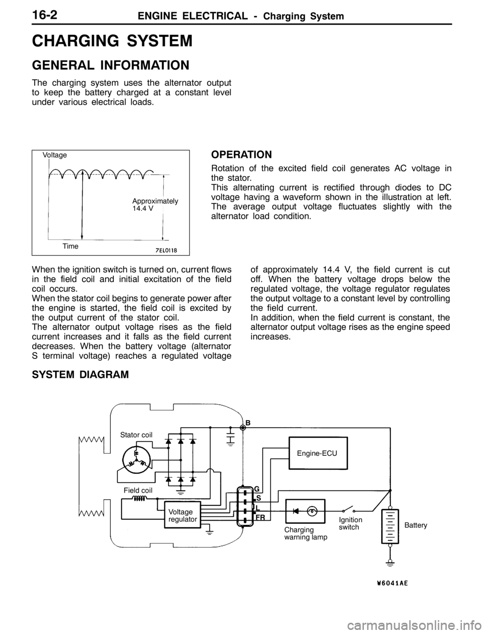
CHARGING SYSTEM
GENERAL INFORMATION
The charging system uses the alternator output
to keep the battery charged at a constant level
under various electrical loads.
OPERATION
Rotation of the excited field coil generates AC voltage in
the stator.
This alternating current is rectified through diodes to DC
voltage having a waveform shown in the illustration at left.
The average output voltage fluctuates slightly with the
alternator load condition.
When the ignition switch is turned on, current flows
in the field coil and initial excitation of the field
coil occurs.
When the stator coil begins to generate power after
the engine is started, the field coil is excited by
the output current of the stator coil.
The alternator output voltage rises as the field
current increases and it falls as the field current
decreases. When the battery voltage (alternator
S terminal voltage) reaches a regulated voltageof approximately 14.4 V, the field current is cut
off. When the battery voltage drops below the
regulated voltage, the voltage regulator regulates
the output voltage to a constant level by controlling
the field current.
In addition, when the field current is constant, the
alternator output voltage rises as the engine speed
increases.
SYSTEM DIAGRAM
Stator coil
Field coil
Voltage
regulatorEngine-ECU
Charging
warning lampIgnition
switchBattery B
G
L
FRS
Voltage
Time
Approximately
14.4 V
Page 749 of 1449

ENGINE ELECTRICAL -Starting System16-17
STARTING SYSTEM
GENERAL INFORMATION
If the ignition switch is turned to the “START”
position, current flows in the pull-in and holding
coils provided inside magnetic switch, attracting
the plunger. When the plunger is attracted, the
lever connected to the plunger is actuated to
engage the starter clutch.
On the other hand, attracting the plunger will turn
on the magnetic switch, allowing the B terminaland M terminal to conduct. Thus, current flows to
engage the starter motor.
When the ignition switch is returned to the “ON”
position after starting the engine, the starter clutch
is disengaged from the ring gear.
An overrunning clutch is provided between the
pinion and the armature shaft, to prevent damage
to the starter.
SYSTEM DIAGRAM
Pull-in coilHolding coil
Ignition
switch
BatteryArmature
Brush
YokePlunger
Lever
Over-running
clutch
Pinion shaft
STARTER MOTOR SPECIFICATIONS
ItemsSpecifications
TypeReduction drive with planetary gear
Rated output kW/V1.2/12
No. of pinion teeth8
SERVICE SPECIFICATIONS
ItemsStandard valueLimit
Pinion gap mm0.5 - 2.0-
Commutator outer diameter mm29.428.8
Commutator runout mm0.050.1
Commutator undercut mm0.50.2
Brush length mm-7.0
Page 758 of 1449

ENGINE ELECTRICAL -Ignition System16-26
IGNITION SYSTEM
GENERAL INFORMATION
This system is equipped with two ignition coils (A
and B) with built-in power transistors for the No.
1 and No. 4 cylinders and the No. 2 and No. 3
cylinders respectively.
Interruption of the primary current flowing in the
primary side of ignition coil A generates a high
voltage in the secondary side of ignition coil A.
The high voltage thus generated is applied to the
spark plugs of No. 1 and No. 4 cylinders to generate
sparks. At the time that the sparks are generated
at both spark plugs, if one cylinder is at the
compression stroke, the other cylinder is at the
exhaust stroke, so that ignition of the compressed
air/fuel mixture occurs only for the cylinder which
is at the compression stroke.
In the same way, when the primary current flowing
in ignition coil B is interrupted, the high voltage
thus generated is applied to the spark plugs of
No. 2 and No. 3 cylinders.
The Engine-ECU turns the two power transistors
inside the ignition coils alternately on and off. Thiscauses the primary currents in the ignition coils
to be alternately interrupted and allowed to flow
to fire the cylinders in the order 1-3-4-2.
The Engine-ECU determines which ignition coil
should be controlled by means of the signals from
the camshaft position sensor which is incorporated
in the camshaft and from the crank angle sensor
which is incorporated in the crankshaft. It also
detects the crankshaft position in order to provide
ignition at the most appropriate timing in response
to the engine operation conditions. It also detects
the crankshaft position in order to provide ignition
at the most appropriate timing in response to the
engine operation conditions.
When the engine is cold or operated at high
altitudes, the ignition timing is slightly advanced
to provide optimum performance.
When the automatic transmission shifts gears, the
ignition timing is also retarded in order to reduce
output torque, thereby alleviating shifting shocks.
SYSTEM DIAGRAM
Barometric pressure sensor
Intake air temperature sensor
Engine coolant temperature sensor
Camshaft position sensor
Crank angle sensor
Ignition switch - ST
Vehicle speed signalEngine-ECU
Ignition coil A
Ignition coil B Ignition switch
Spark plugBattery
To tachometerCylinder No. Air flow sensor
1 4
23
Detonation sensor
Page 771 of 1449

17-1
ENGINE AND
EMISSION
CONTROL
CONTENTS
ENGINE CONTROL SYSTEM 2.........
GENERAL INFORMATION 2................
SERVICE SPECIFICATIONS 2...............
ON-VEHICLE SERVICE 2...................
Accelerator Cable Check and
Adjustment 2................................
ACCELERATOR CABLE AND PEDAL 3......
EMISSION CONTROL SYSTEM 4......
GENERAL INFORMATION 4................
Emission Control Device Reference
Table 4.....................................
SERVICE SPECIFICATIONS 5..............
VACUUM HOSE 5..........................
Vacuum Hose Piping Diagram 5..............
Vacuum Circuit Diagram 6....................
Vacuum Hose Check 7......................
Vacuum Hose Installation 7..................
CRANKCASE EMISSION CONTROL
SYSTEM 8................................
General Information 8........................
System Diagram 8..........................
Component Location 9.......................
Positive Crankcase Ventilation System Check 9....
PCV Valve Check 9.........................
EVAPORATIVE EMISSION CONTROL
SYSTEM 10...............................
General Information 10.......................
System Diagram 10..........................
Component Location 10......................
Purge Control System Check 11...............
Purge Port Vacuum Check 11.................
Purge Control Solenoid Valve Check 12.........
Check Valve Check 12.......................
EXHAUST GAS RECIRCULATION (EGR)
SYSTEM 13...............................
General Information 13.......................
Operation 13................................
System Diagram 13..........................
Component Location 14......................
Exhaust Gas Recirculation (EGR) Control System
Check 14...................................
EGR Valve Check 15.........................
EGR Port Vacuum Check 15..................
EGR Control Solenoid Valve Check 16..........
EGR VALVE 17............................
CANISTER 18.............................
CATALYTIC CONVERTER 19................
General Information 19.......................
Page 775 of 1449

ENGINE AND EMISSION CONTROL -Emission Control System17-5
SERVICE SPECIFICATIONS
ItemsStandard value
Purge control solenoid valve coil resistance (at 20_C)Ω30 - 34
EGR control solenoid valve coil resistance (at 20_C)Ω29 - 35
VACUUM HOSE
VACUUM HOSE PIPING DIAGRAM
Fuel
pressure
control
solenoid
valve
Oxygen
sensor
(front)
Check
valve
Fuel
pressure
regulator
PCV valve To
fuel tank
Oxygen sensor (rear) From
fuel pump
Air
inletEGR control
solenoid valve
Purge
control
solenoid
valveCanisterFrom
fuel tank
EGR
valve Injector
Three - way
catalytic converter A
P
E
Page 776 of 1449

ENGINE AND EMISSION CONTROL -Emission Control System17-6
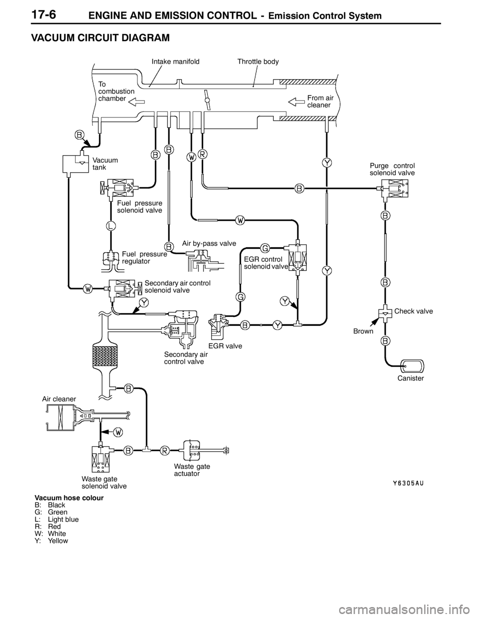
VACUUM CIRCUIT DIAGRAM
Vacuum hose colour
B: Black
G: Green
L: Light blue
R: Red
W: White
Y: YellowFrom air
cleaner
Intake manifoldThrottle body
To
combustion
chamber
Fuel pressure
regulator
EGR control
solenoid valve
Canister
EGR valve
Brown
Check valve Vacuum
tank
Fuel pressure
solenoid valve
Air by-pass valve
Secondary air control
solenoid valve
Secondary air
control valvePurge control
solenoid valve
Air cleaner
Waste gate
solenoid valveWaste gate
actuator