Page 777 of 1449
ENGINE AND EMISSION CONTROL -Emission Control System17-7
VACUUM HOSE CHECK
1. Using the piping diagram as a guide, check to be sure
that the vacuum hoses are correctly connected.
2. Check the connection condition of the vacuum hoses,
(removed, loose, etc.) and check to be sure that there
are no bends or damage.
VACUUM HOSE INSTALLATION
1. When connecting the vacuum hoses, they should be
securely inserted onto the nipples.
2. Connect the hoses correctly, using the vacuum hose piping
diagram as a guide.
Page 778 of 1449
ENGINE AND EMISSION CONTROL -Emission Control System17-8
CRANKCASE EMISSION CONTROL SYSTEM
GENERAL INFORMATION
The crankcase emission control system prevents
blow-by gases from escaping inside the crankcase
into the atmosphere.
Fresh air is sent from the air cleaner into the
crankcase through the breather hose. The air
becomes mixed with the blow-by gases inside the
crankcase.
The blow-by gas inside the crankcase is drawn
into the intake manifold through the positivecrankcase ventilation (PCV) valve.
The PCV valve lifts the plunger according to the
intake manifold vacuum so as to regulate the flow
of blow-by gas properly. In other words, the blow-by
gas flow is regulated during low load engine
operation to maintain engine stability, while the flow
is increased during high load operation to improve
the ventilation performance.
SYSTEM DIAGRAM
Ventilation hose
PCV valve Breather hose
Page 780 of 1449

ENGINE AND EMISSION CONTROL -Emission Control System
Vacuum tank
Alternator
Purge control solenoid valve
17-10
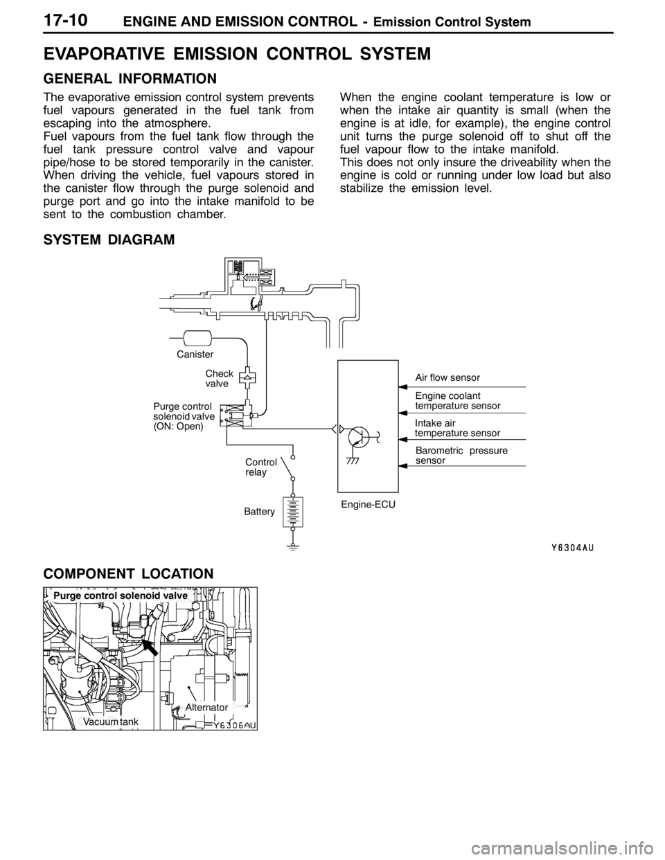
EVAPORATIVE EMISSION CONTROL SYSTEM
GENERAL INFORMATION
The evaporative emission control system prevents
fuel vapours generated in the fuel tank from
escaping into the atmosphere.
Fuel vapours from the fuel tank flow through the
fuel tank pressure control valve and vapour
pipe/hose to be stored temporarily in the canister.
When driving the vehicle, fuel vapours stored in
the canister flow through the purge solenoid and
purge port and go into the intake manifold to be
sent to the combustion chamber.When the engine coolant temperature is low or
when the intake air quantity is small (when the
engine is at idle, for example), the engine control
unit turns the purge solenoid off to shut off the
fuel vapour flow to the intake manifold.
This does not only insure the driveability when the
engine is cold or running under low load but also
stabilize the emission level.
SYSTEM DIAGRAM
BatteryIntake air
temperature sensor
Barometric pressure
sensor
Check
valve
Canister
Control
relay
Purge control
solenoid valve
(ON: Open)
Engine-ECUEngine coolant
temperature sensor Air flow sensor
COMPONENT LOCATION
Page 783 of 1449

ENGINE AND EMISSION CONTROL -Emission Control System17-13
EXHAUST GAS RECIRCULATION (EGR) SYSTEM
GENERAL INFORMATION
The exhaust gas recirculation (EGR) system lowers
the nitrogen oxide (NOx) emission level. When the
air/fuel mixture combustion temperature is high,
a large quantity of nitrogen oxides (NOx) is
generated in the combustion chamber. Therefore,
this system recirculates part of emission gas fromthe exhaust port of the cylinder head to the
combustion chamber through the intake manifold
to decrease the air/fuel mixture combustion
temperature, resulting in reduction of NOx.
The EGR flow rate is controlled by the EGR valve
so as not to decrease the driveability.
OPERATION
The EGR valve is being closed and does not
recirculate exhaust gases under one of the following
conditions. Otherwise, the EGR valve is opened
and recirculates exhaust gases.DThe engine coolant temperature is low.
DThe engine is at idle.
DThe throttle valve is widely opened.
SYSTEM DIAGRAM
ON Throttle body
EGR control
solenoid valve
Engine
control
relay
Battery EGR valve
Crank angle sensor
Throttle position sensor Engine-ECU
Engine coolant
temperature sensor Air flow sensor
Page 1016 of 1449
POWER PLANT MOUNT - General Information32-2
GENERAL INFORMATION
Inertia principal axes system is incorporated into
the engine mount system.Upper installation of roll mount reduces engine
rolling, and increase of insulator bore also reduces
idle vibration.
CONSTRUCTION DIAGRAM
Transmission mount Engine mount
Rear roll rod bracket
Front roll stopper
Front roll mount bracketRear roll mount bracket
Crossmember
Crossmember bar
CentermemberRear roll rod assembly
Page 1099 of 1449

ABS <4WD> -On-vehicle Service35B-29
The result should be as shown in the following diagram.
Approx. 0.05 seconds
Pedal operationDepressed
Released
Solenoid valve
positionIncrease in pressure
Steady pressure
Reduction in pressure
Checking the
brake forceLock
Drag force when the pedal is freeMUT-IIactuator test
(Item No. 01, 02, 03, 04) start
2 seconds
1 seconds
6. If the result of inspection is abnormal, correct according to the following “Diagnosis Table.”
Diagnosis Table
No.MUT-II
display
OperationJudgementProbable
cause
Remedy
display
NormalAbnormal
cause
01FR VALVE(1) Depress the brake
pedal to lock wheel.
(2) Using the MUT-II,
select the wheel to be
checkedandforcethe
Brake force
released for 3
seconds after
locking.Wheel does
not lock when
brake pedal
is depressed.Clogged
brake line
other than
hydraulic unitCheck and
clean brake
line.
02FL VALVEchecked and force the
actuator to operate.
(3) Check the brake force
for the selected wheel
using a brake force
ttbttith
Clogged
hydraulic
circuit in
hydraulic unitReplace
hydraulic unit
assembly.
03RR VALVE
g
tester or by rotating the
wheel by hand.Brake force is
not released.Incorrect
hydraulic unit
brake tube
connectionConnect
correctly.
04RL VALVEHydraulic unit
solenoid
valve not
functioning
correctlyReplace
hydraulic unit
assembly.
7. After checking, turn the ignition switch to the “LOCK” (OFF) position and then disconnect the MUT-II.
REMEDY FOR A FLAT BATTERY
When booster cables are used to start the engine when the
battery is completely flat and then the vehicle is immediately
driven without waiting for the battery to recharge itself to
some extent, the engine may misfire, and driving might not
be possible. This happens because ABS consumes a great
amount of current for its self-check function. If this happens,
recharge the battery fully.
Caution
The vehicle posture will be unstable during braking, so
do not drive the vehicle with the ABS-ECU connector
disconnected or with the ABS not operating for any other
reason.