Page 747 of 1449
ENGINE ELECTRICAL -Charging System16-15
"BAROTOR INSTALLATION
After installing the rotor, remove the wire used to fix the brush.
INSPECTION
ROTOR CHECK
1. Check the continuity between the rotor coil slip rings,
and replace the rotor if the resistance value is not at
the standard value.
Standard value: 3 - 5Ω
2. Check the continuity between the slip ring and core, and
if there is continuity, replace the rotor.
STATOR CHECK
1. Check the continuity between the coil leads, and if there
is continuity, replace the stator.
2. Check the continuity between the coil and core, and if
there is continuity, replace the stator.
Wire
Page 748 of 1449

ENGINE ELECTRICAL -Charging System16-16
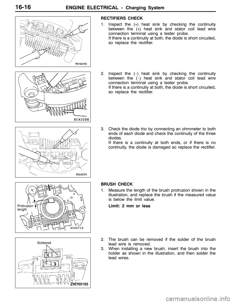
RECTIFIERS CHECK
1. Inspect the (+) heat sink by checking the continuity
between the (+) heat sink and stator coil lead wire
connection terminal using a tester probe.
If there is a continuity at both, the diode is short circuited,
so replace the rectifier.
2. Inspect the ( - ) heat sink by checking the continuity
between the ( - ) heat sink and stator coil lead wire
connection terminal using a tester probe.
If there is a continuity at both, the diode is short circuited,
so replace the rectifier.
3. Check the diode trio by connecting an ohmmeter to both
ends of each diode and check the continuity of the three
diodes.
If there is a continuity at both ends, or if there is no
continuity, the diode is damaged so replace the rectifier.
BRUSH CHECK
1. Measure the length of the brush protrusion shown in the
illustration, and replace the brush if the measured value
is below the limit value.
Limit: 2 mm or less
2. The brush can be removed if the solder of the brush
lead wire is removed.
3. When installing a new brush, insert the brush into the
holder as shown in the illustration, and then solder the
lead wires.
Protrusion
length
Soldered
Page 749 of 1449

ENGINE ELECTRICAL -Starting System16-17
STARTING SYSTEM
GENERAL INFORMATION
If the ignition switch is turned to the “START”
position, current flows in the pull-in and holding
coils provided inside magnetic switch, attracting
the plunger. When the plunger is attracted, the
lever connected to the plunger is actuated to
engage the starter clutch.
On the other hand, attracting the plunger will turn
on the magnetic switch, allowing the B terminaland M terminal to conduct. Thus, current flows to
engage the starter motor.
When the ignition switch is returned to the “ON”
position after starting the engine, the starter clutch
is disengaged from the ring gear.
An overrunning clutch is provided between the
pinion and the armature shaft, to prevent damage
to the starter.
SYSTEM DIAGRAM
Pull-in coilHolding coil
Ignition
switch
BatteryArmature
Brush
YokePlunger
Lever
Over-running
clutch
Pinion shaft
STARTER MOTOR SPECIFICATIONS
ItemsSpecifications
TypeReduction drive with planetary gear
Rated output kW/V1.2/12
No. of pinion teeth8
SERVICE SPECIFICATIONS
ItemsStandard valueLimit
Pinion gap mm0.5 - 2.0-
Commutator outer diameter mm29.428.8
Commutator runout mm0.050.1
Commutator undercut mm0.50.2
Brush length mm-7.0
Page 750 of 1449
ENGINE ELECTRICAL -Starting System16-18
STARTER
REMOVAL AND INSTALLATION
Pre-removal and Post-installation Operation
DUnder Cover Removal and Installation (Refer to GROUP51 - Front Bumper.)
DCrossmember Bar Removal and Installation (Refer to GROUP 32 - Engine Roll Stopper, Centermember.)
DFront Exhaust Pipe Assembly Removal and Installation (Refer to GROUP 15.)
30±3 N·m
1 2
30±3 N·m 13±2 N·m
Removal steps
1. Starter connector
2. Starter
INSPECTION
PINION GAP ADJUSTMENT
1. Disconnect field coil wire from M-terminal of magnetic
switch.
2. Connect a 12 V battery between S-terminal and
M-terminal.
3. Set switch to “ON” position, and pinion will move out.
Caution
This test must be performed quickly (in less than
10 seconds) to prevent coil from burning.
4. Check pinion to stopper clearance (pinion gap) with a
thickness gauge.
Standard value: 0.5 - 2.0 mmS
Switch
Battery
Field coil wire M
B
Stopper
Pinion gap
Pinion
Page 751 of 1449

ENGINE ELECTRICAL -Starting System16-19
5. If pinion gap is out of specification, adjust by adding or
removing gaskets between magnetic switch and front
bracket.
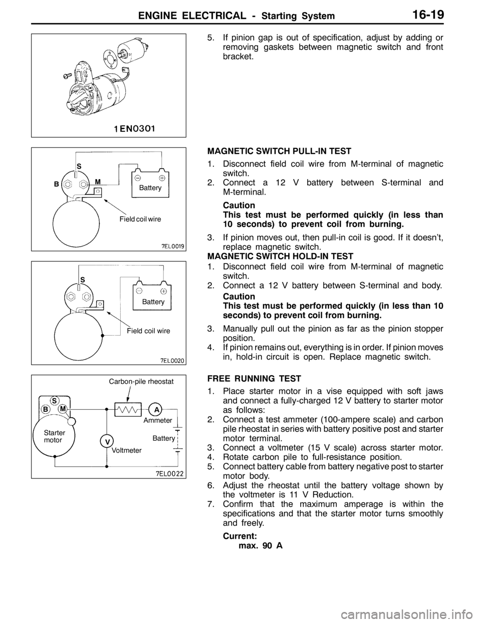
MAGNETIC SWITCH PULL-IN TEST
1. Disconnect field coil wire from M-terminal of magnetic
switch.
2. Connect a 12 V battery between S-terminal and
M-terminal.
Caution
This test must be performed quickly (in less than
10 seconds) to prevent coil from burning.
3. If pinion moves out, then pull-in coil is good. If it doesn’t,
replace magnetic switch.
MAGNETIC SWITCH HOLD-IN TEST
1. Disconnect field coil wire from M-terminal of magnetic
switch.
2. Connect a 12 V battery between S-terminal and body.
Caution
This test must be performed quickly (in less than 10
seconds) to prevent coil from burning.
3. Manually pull out the pinion as far as the pinion stopper
position.
4. If pinion remains out, everything is in order. If pinion moves
in, hold-in circuit is open. Replace magnetic switch.
FREE RUNNING TEST
1. Place starter motor in a vise equipped with soft jaws
and connect a fully-charged 12 V battery to starter motor
as follows:
2. Connect a test ammeter (100-ampere scale) and carbon
pile rheostat in series with battery positive post and starter
motor terminal.
3. Connect a voltmeter (15 V scale) across starter motor.
4. Rotate carbon pile to full-resistance position.
5. Connect battery cable from battery negative post to starter
motor body.
6. Adjust the rheostat until the battery voltage shown by
the voltmeter is 11 V Reduction.
7. Confirm that the maximum amperage is within the
specifications and that the starter motor turns smoothly
and freely.
Current:
max. 90 A
Field coil wire S
M
Battery
B
Field coil wire S
Battery
M S
B
Starter
motorAmmeter
Battery
Voltmeter
Carbon-pile rheostat
A
V
Page 752 of 1449
ENGINE ELECTRICAL -Starting System16-20
MAGNETIC SWITCH RETURN TEST
1. Disconnect field coil wire from M-terminal of magnetic
switch.
2. Connect a 12 V battery between M-terminal and body.
Caution
This test must be performed quickly (in less than
10 seconds) to prevent coil from burning.
3. Pull pinion out and release. If pinion quickly returns to
its original position, everything is in order. If it doesn’t,
replace magnetic switch.
Caution
Be careful not to get your fingers caught when pulling
out the pinion.
Field coil wire M
Battery
Page 753 of 1449
ENGINE ELECTRICAL -Starting System16-21
DISASSEMBLY AND REASSEMBLY
1 1713
1512
4 3
211
6 1614
1098
7 5
182021
19
22
Disassembly steps
1. Cover
2. Screw
AA"3. Magnetic switch
4. Screw
5. Through
6. Rear bracket
7. Brush holder
8. Rear bearing
AB"9. Armature
10. Yoke assembly
AB"11. Ball12. Packing A
13. Packing B
14. Plate
15. Planetary gear
16. Lever
AC""AA17. Snap ring
AC""AA18. Stop ring
19. Overrunning clutch
20. Internal gear
21. Planetary gear holder
22. Front bracket
Page 754 of 1449

ENGINE ELECTRICAL -Starting System16-22
DISASSEMBLY SERVICE POINTS
AA"MAGNETIC SWITCH REMOVAL
Disconnect field coil wire from “M” terminal of magnetic switch.
AB"ARMATURE/BALL REMOVAL
Caution
When removing the armature, take care not to lose the
ball (which is used as a bearing) in the armature end.
AC"SNAP RING/STOP RING REMOVAL
1. Press stop ring off snap ring with a suitable socket.
2. Remove snap ring with snap ring pliers and then remove
stop ring and overrunning clutch.
STARTER MOTOR PARTS CLEANING
1. Do not immerse parts in cleaning solvent. Immersing the
yoke and field coil assembly and/or armature will damage
insulation. Wipe motor assembly with a cloth only.
2. Do not immerse drive unit in cleaning solvent. Overrunning
clutch is pre-lubricated at the factory and solvent will wash
lubrication from clutch
3. The drive unit may be cleaned with a brush moistened
with cleaning solvent and wiped dry with a cloth.
“B” terminal“S” terminal
“M” terminalField coil
wire
Socket
Overrunning
clutch Stop ring
Pinion gear
Snap ring pliers
Overrunning
clutch Pinion gear Snap ring