2007 MITSUBISHI LANCER EVOLUTION ECU
[x] Cancel search: ECUPage 1283 of 1449

SRS -Troubleshooting52B-39
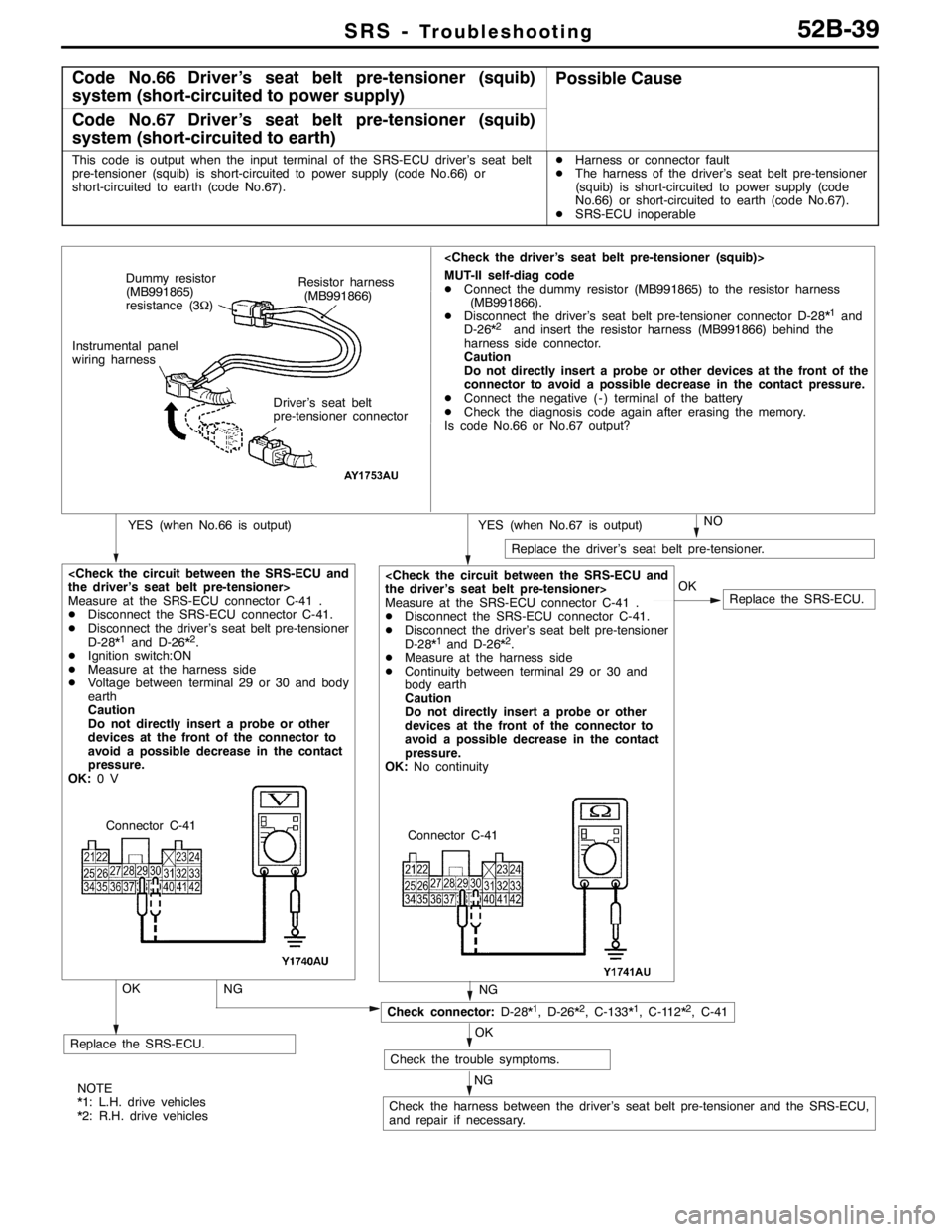
Code No.66 Driver’s seat belt pre-tensioner (squib)
system (short-circuited to power supply)Possible Cause
Code No.67 Driver’s seat belt pre-tensioner (squib)
system (short-circuited to earth)
This code is output when the input terminal of the SRS-ECU driver’s seat belt
pre-tensioner (squib) is short-circuited to power supply (code No.66) or
short-circuited to earth (code No.67).DHarness or connector fault
DThe harness of the driver’s seat belt pre-tensioner
(squib) is short-circuited to power supply (code
No.66) or short-circuited to earth (code No.67).
DSRS-ECU inoperable
Replace the SRS-ECU. OK
Measure at the SRS-ECU connector C-41 .
DDisconnect the SRS-ECU connector C-41.
DDisconnect the driver’s seat belt pre-tensioner
D-28*
1and D-26*2.
DMeasure at the harness side
DContinuity between terminal 29 or 30 and
body earth
Caution
Do not directly insert a probe or other
devices at the front of the connector to
avoid a possible decrease in the contact
pressure.
OK:No continuity
NO
Replace the driver’s seat belt pre-tensioner.
MUT-II self-diag code
DConnect the dummy resistor (MB991865) to the resistor harness
(MB991866).
DDisconnect the driver’s seat belt pre-tensioner connector D-28*
1and
D-26*2and insert the resistor harness (MB991866) behind the
harness side connector.
Caution
Do not directly insert a probe or other devices at the front of the
connector to avoid a possible decrease in the contact pressure.
DConnect the negative ( - ) terminal of the battery
DCheck the diagnosis code again after erasing the memory.
Is code No.66 or No.67 output?
YES (when No.67 is output)YES (when No.66 is output)
Replace the SRS-ECU.
Measure at the SRS-ECU connector C-41 .
DDisconnect the SRS-ECU connector C-41.
DDisconnect the driver’s seat belt pre-tensioner
D-28*
1and D-26*2.
DIgnition switch:ON
DMeasure at the harness side
DVoltage between terminal 29 or 30 and body
earth
Caution
Do not directly insert a probe or other
devices at the front of the connector to
avoid a possible decrease in the contact
pressure.
OK:0V
NG
Check connector:D-28*1, D-26*2, C-133*1, C-112*2, C-41
Check the trouble symptoms.
Check the harness between the driver’s seat belt pre-tensioner and the SRS-ECU,
and repair if necessary.
NG
OK
NG
OKResistor harness
(MB991866) Dummy resistor
(MB991865)
resistance (3Ω)
Instrumental panel
wiring harness
Driver’s seat belt
pre-tensioner connector
Connector C-41
Connector C-41
NOTE
*1: L.H. drive vehicles
*2: R.H. drive vehicles
Page 1284 of 1449

SRS -Troubleshooting52B-40
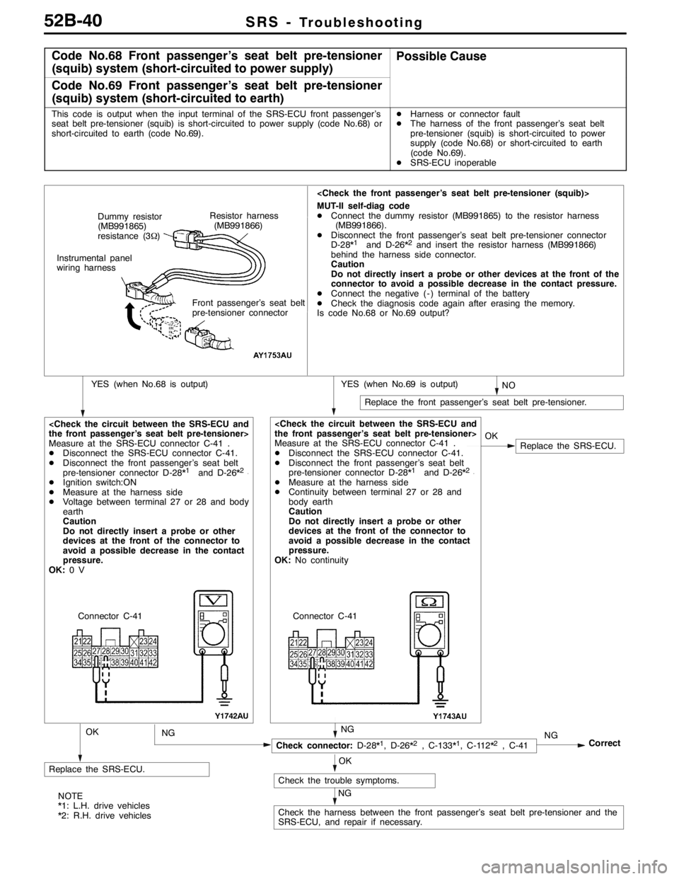
Code No.68 Front passenger’s seat belt pre-tensioner
(squib) system (short-circuited to power supply)Possible Cause
Code No.69 Front passenger’s seat belt pre-tensioner
(squib) system (short-circuited to earth)
This code is output when the input terminal of the SRS-ECU front passenger’s
seat belt pre-tensioner (squib) is short-circuited to power supply (code No.68) or
short-circuited to earth (code No.69).DHarness or connector fault
DThe harness of the front passenger’s seat belt
pre-tensioner (squib) is short-circuited to power
supply (code No.68) or short-circuited to earth
(code No.69).
DSRS-ECU inoperable
NO
Replace the front passenger’s seat belt pre-tensioner.
MUT-II self-diag code
DConnect the dummy resistor (MB991865) to the resistor harness
(MB991866).
DDisconnect the front passenger’s seat belt pre-tensioner connector
D-28*
1and D-26*2and insert the resistor harness (MB991866)
behind the harness side connector.
Caution
Do not directly insert a probe or other devices at the front of the
connector to avoid a possible decrease in the contact pressure.
DConnect the negative ( - ) terminal of the battery
DCheck the diagnosis code again after erasing the memory.
Is code No.68 or No.69 output?
YES (when No.69 is output)YES (when No.68 is output)
Replace the SRS-ECU.
Measure at the SRS-ECU connector C-41 .
DDisconnect the SRS-ECU connector C-41.
DDisconnect the front passenger’s seat belt
pre-tensioner connector D-28*
1and D-26*2.
DIgnition switch:ON
DMeasure at the harness side
DVoltage between terminal 27 or 28 and body
earth
Caution
Do not directly insert a probe or other
devices at the front of the connector to
avoid a possible decrease in the contact
pressure.
OK:0V
NG
Replace the SRS-ECU.
Correct
Check connector:D-28*1, D-26*2, C-133*1, C-112*2, C-41
Check the trouble symptoms.
Check the harness between the front passenger’s seat belt pre-tensioner and the
SRS-ECU, and repair if necessary.OK
Measure at the SRS-ECU connector C-41 .
DDisconnect the SRS-ECU connector C-41.
DDisconnect the front passenger’s seat belt
pre-tensioner connector D-28*
1and D-26*2.
DMeasure at the harness side
DContinuity between terminal 27 or 28 and
body earth
Caution
Do not directly insert a probe or other
devices at the front of the connector to
avoid a possible decrease in the contact
pressure.
OK:No continuity
NG
OK
NG
OK
NG
Resistor harness
(MB991866) Dummy resistor
(MB991865)
resistance (3Ω)
Instrumental panel
wiring harness
Front passenger’s seat belt
pre-tensioner connector
Connector C-41 Connector C-41
NOTE
*1: L.H. drive vehicles
*2: R.H. drive vehicles
Page 1285 of 1449

SRS -Troubleshooting52B-41
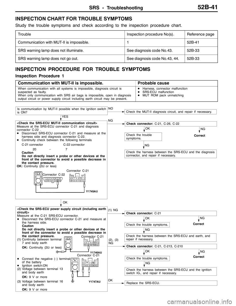
INSPECTION CHART FOR TROUBLE SYMPTOMS
Study the trouble symptoms and check according to the inspection procedure chart.
TroubleInspection procedure No(s).Reference page
Communication with MUT-II is impossible.152B-41
SRS warning lamp does not illuminate.See diagnosis code No.43.52B-33
SRS warning lamp does not go out.See diagnosis code No.43, 44.52B-33
INSPECTION PROCEDURE FOR TROUBLE SYMPTOMS
Inspection Procedure 1
Communication with MUT-II is impossible.
Probable cause
When communication with all systems is impossible, diagnosis circuit is
suspected as faulty.
When only communication with SRS air bags is impossible, open in diagnosis
output circuit or power supply circuit including earth circuit may be present.DHarness, connector malfunction
DSRS-ECU malfunction
DMUT ROM pack unmatching
OKReplace the SRS-ECU.
NG
NG
Check the harness between the SRS-ECU and the ignition
switch IG1, and repair if necessary.
NOCheck the MUT-II diagnosis circuit, and repair if necessary.
OK
Check the trouble symptoms.
NG
Correct
NG
Check the harness between the SRS-ECU and earth, and
repair if necessary.
OK
Check the trouble symptoms.
NG
Correct
OK
OK
Check the trouble
symptoms.
Check the harness between the SRS-ECU and the diagnosis
connector, and repair if necessary.
YES
(1) NG
Check connector:C-21
(2), (3)
NG
Check connector:C-21, C-213, C-210
Measure at the C-21 SRS-ECU connector.
DDisconnect the SRS-ECU connector C-21 and measure at
the harness side.
Caution
Do not directly insert a probe or other devices at the
front of the connector to avoid a possible decrease in
the contact pressure.
(1) Continuity between terminal
7 and body earth
OK:Continuity (2Ωor less)
DConnect the negative ( - ) terminal
of the battery
DIgnition switch:ON
(2) Voltage between terminal 13
and body earth
OK:9 V or more
(3) Voltage between terminal 16
and body earth
OK:9 V or more
NG
Correct
Check connector:C-21, C-26, C-22
Is communication by MUT-II possible when the ignition switch
is ON?
NG
Measure at the SRS-ECU connector C-21 and diagnosis
connector C-22 .
DDisconnect SRS-ECU connector C-21 and measure at the
harness side and diagnosis connector C-22.
DContinuity check between the following terminals
C-21 connector C-22 connector
20 – 7
Caution
Do not directly insert a probe or other devices at the
front of the connector to avoid a possible decrease in
the contact pressure.
OK:Continuity (2Ωor less)
Connector C-21
Connector C-22
Connector C-21
Connector C-21
Page 1286 of 1449

SRS - SRS Maintenance52B-42
SRS MAINTENANCE
The SRS must be inspected by an authorized dealer 10 years
after the date of vehicle registration.
SRS WARNING LAMP CHECK
Turn the ignition switch to the ON position. Does the SRS
warning lamp illuminate for about 7 seconds, and then go
out? If yes, SRS system is functioning properly. If no, refer
to page 52B-6.
SRS COMPONENT VISUAL CHECK
Turn the ignition key to LOCK (OFF) position, disconnect
the negative ( - ) battery cable and tape the terminal.
Caution
Wait at least 60 seconds after disconnecting the battery
cable before doing any further work. (Refer to P.52B-3.)
SRS CONTROL UNIT (SRS-ECU)
1. Check SRS-ECU case and brackets for dents, cracks,
deformation or rust.
Caution
The SRS may not activate if the SRS-ECU is not
installed properly, which could result in serious injury
or death to the vehicle’s driver or front passenger.
2. Check connector for damage, and terminals for
deformation or rust.
Replace SRS-ECU if it fails visual check.
(Refer to P.52B-50.)
SRS warning lamp
Insulating tape
Battery
Battery
( - ) cable
SRS-ECU
Page 1289 of 1449

SRS - Post-collision Diagnosis52B-45
POST-COLLISION DIAGNOSIS
Whether or not the air bags have deployed, check and service
the vehicle after collision as follows:
SRS-ECU MEMORY CHECK
1. Connect the MUT-IIto the diagnosis connector. (Refer
to GROUP 00 – How to Use Troubleshooting/Inspection
Service Points.)
Caution
Refer to that the ignition switch is LOCK(OFF) when
connecting or disconnecting MUT-II.
2. Read (and write down) all displayed diagnosis codes.
(Refer to P.52B-9.)
NOTE
If battery power supply has been shut down by the
collision, the MUT-IIcannot communicate with the
SRS-ECU. Check and, repair if necessary, the instrument
panel wiring harness before the next job.
3. Use the the MUT-IIto read the data list (how long trouble(s)
have continued and how often memory have been
erased).
Data list
NoService Data ItemApplicability
92Number indication how often the memory is cleared.Maximum time to be stored: 250
93How long problem have lasted (How long it takes
from the occurrence of the problem till the first air bag
squib igniting signal)Maximum time to be stored: 9999 minutes
(approximately 7 days)
94How long problem(s) have lasted (How long it takes
from the first air bag squib igniting signal till now.)
4. Erase the diagnosis codes and after waiting 5 seconds
or more read (and write down) all displayed diagnosis
codes. (Refer to P.52B-9.)
Page 1290 of 1449

SRS - Post-collision Diagnosis52B-46
REPAIR PROCEDURE
DEPLOYED DRIVER’S AND FRONT PASSENGER’S AIR
BAGS OR OPERATED SEAT BELT PRE-TENSIONER.
1. Replace the following parts with new ones.
DSRS-ECU (Refer to P.52B-50.)
DDriver’s air bag module (Refer to P.52B-52.)
DFront passenger’s air bag module (Refer to P.52B-52.)
DSeat belt with pre-tensioner (Refer to P.52B-61.)
2. Check the following parts and replace if malfunction is
found:
DClock spring (Refer to P.52B-52.)
DSteering wheel, steering column and intermediate
joint
(1) Check the wiring harness (built into steering
wheel) and connectors for damage, and terminals
for deformation.
(2) Check the driver’s air bag module for proper
installation to the steering wheel.
(3) Check the steering wheel for noise, binds or
difficult operation and excessive free play.
3. Check the harness for binding, connectors for damage,
poor connections, and terminals for deformation.
(Refer to P.52B-44.)
UNDEPLOYED AIR BAGS OR UNOPERATED SEAT BELT
WITH PRE-TENSIONER IN LOW-SPEED COLLISION
Check the SRS components and seat belt with pre-tensioner.
If visible damage such as dents, cracks, or deformation are
found on the SRS components and seat belt with
pre-tensioner, replace them with new ones. Concerning parts
removed for inspection, replacement with new parts and
cautions in working, refer to INDIVIDUAL COMPONENT
SERVICE, P.52B-49.
Page 1291 of 1449

SRS - Post-collision Diagnosis52B-47
SRS-ECU
1. Check the SRS-ECU case and bracket for dents, cracks
or deformation.
2. Check the connector for damage, and terminals for
deformation.
3. Check the SRS-ECU and bracket for proper installation.
Driver’s and passenger’s air bag modules
1. Check the covers for dents, cracks or deformation.
2. Check the connectors for damage, the terminals
deformities, and the harness for binds.
3. Check the air bag inflator cases for dents, cracks or
deformities.
4. Check the air bag modules for proper installation.
Clock spring
1. Check the clock spring connectors and protective tubes
for damage, and terminals for deformation.
2. Visually check the case for damage.
SRS-ECU
Inflator
Connector
Connector
Steering
wheel - driver’s
air bag module
assembly
Connector Inflator case
Protective tubesCase
Page 1293 of 1449

SRS - Individual Component Service/Warning/Caution Labels52B-49
INDIVIDUAL COMPONENT SERVICE
If the SRS components and seat belt with pre-tensioner are to be removed or replaced as a result of
maintenance, troubleshooting etc., follow the service procedures that follow.
Caution
1. SRS components and seat belt with pre-tensioner should not be subjected to heat, so remove
the SRS-ECU, driver’s air bag module
passenger’s air bag module, clock spring, and seat belt with pre-tensioner before drying or
baking the vehicle after painting.
DFront impact sensor, SRS-ECU, Air bag module, clock spring: 93_C or more
DSeat belt with pre-tensioner: 90_C or more
Recheck SRS system operability after re-installing them.
2. If the SRS components and seat belt with pre-tensioner are removed for the purpose of check,
sheet metal repair, painting, etc., they should be stored in a clean, dry place until they are
reinstalled.
WARNING/CAUTION LABELS
Caution labels on the SRS are attached in the
vehicle as shown. Follow label instructions whenservicing the SRS. If the label(s) are dirty or
damaged, replace with new one(s).
Steering wheel
Driver’s air bag module
Clock springFront passenger’s
air bag moduleSRS-ECU
Sun visor
Steering joint cover
Glove boxCover
Seat belt with pre-tensioner