Page 1344 of 1449

CHASSIS ELECTRICAL -Headlamp Assembly54A-24
HEADLAMP ASSEMBLY
SERVICE SPECIFICATIONS
ItemStandard valueLimit
Headlamp aimingLow beamVertical
direction120mm (0.69_) below hor-
izontal line (H)±0.29_
Horizontal
directionPosition at which the
startup point of 15_is
crossed with vertical line
(V)±0.5_
High beamVertical
directionThe center of high intensi-
ty zone is on the point of
intersection of line (H) and
line (V).- 0.5_of the point of
intersection of line (H)
Horizontal
directionThe center of high intensi-
ty zone is on the point of
intersection of line (V).±0.5_of the center of
line (V)
Measurement of headlamp illuminous intensity
(at high beam)–30,000 cd or more per
one headlamp
NOTES ON HEADLAMP ASSEMBLY:
Plastic outer lens are equipped with headlamp assembly. For handling, care should be taken for
the following items:
DHeadlamps should not be illuminated for more than 3 minutes with scratch preventive protectors,
etc. covered on them.
DMasking such as taping should not be attached on outer lens.
DOuter lens surface should not be rubbed with a sharp-edged tool, etc.
DSpecified wax remover should be used for insistently washing.
DAuthorized Mitsubishi Genuine bulbs should be used.
TROUBLESHOOTING
Headlamps are controlled smart wiring system (SWS). For troubleshooting, refer to GROUP 54B.
NOTE
When ETACS-ECU is defective, headlamps can be illuminated only in a low beam mode as fail-safe
function.
ON-VEHICLE SERVICE
HEADLAMP AIMING
PRE-AIMING INSTRUCTION
1. Inspect for badly rusted or faulty headlamp assemblies.
2. These conditions must be corrected before a satisfactory
adjustment can be made.
3. Inspect tyres inflation, and adjust if necessary.
Page 1359 of 1449
CHASSIS ELECTRICAL-Column Switch54A-39
INSPECTION
LIGHTING SWITCH CONTINUITY CHECK
DRIVE>
Switch PositionTerminal No.
3567891011
OFF
Headlamp
Tail lamp
Passing
Dimmer
Turn signal lamp RH
Turn signal lamp LH
NOTE
On L.H. drive vehicles, integrated column ECU does not allow
lighting switch continuity test. For inspection, troubleshooting
in GROUP 54B should be performed.
COLUMN SWITCH CONTINUITY CHECK (AT SWITCH
BODY)
1. Remove lighting switch and wiper/washer switch.
2. Among individual connectors of column switch body
remaining in steering column, check for continuity between
same number terminals (No. 3 - 11).
Terminal No.Connector at lighting switch side
34567891011
Connector at wiper/
hit hid
3p
washer switch side4
5
6
7
8
9
10
11
At lighting
switch sideAt wiper/washer
switch side
Page 1365 of 1449
54B-1
SMART WIRING
SYSTEM (SWS)
CONTENTS
SPECIAL TOOLS 2...........................
TROUBLESHOOTING 2.......................
Before Commencing Troubleshooting 2...........
Standard Flow of Diagnostic Troubleshooting 2...
Diagnostic Functions 2.........................Diagnosis Code Chart 3........................
Diagnosis Code Inspection Procedures 4.........
Trouble Symptom Chart 7.......................
Inspection Procedures for Trouble Symptoms 10..
Check at ECU Terminals 34.....................
Page 1366 of 1449

SWS -Special Tools/Troubleshooting54B-2
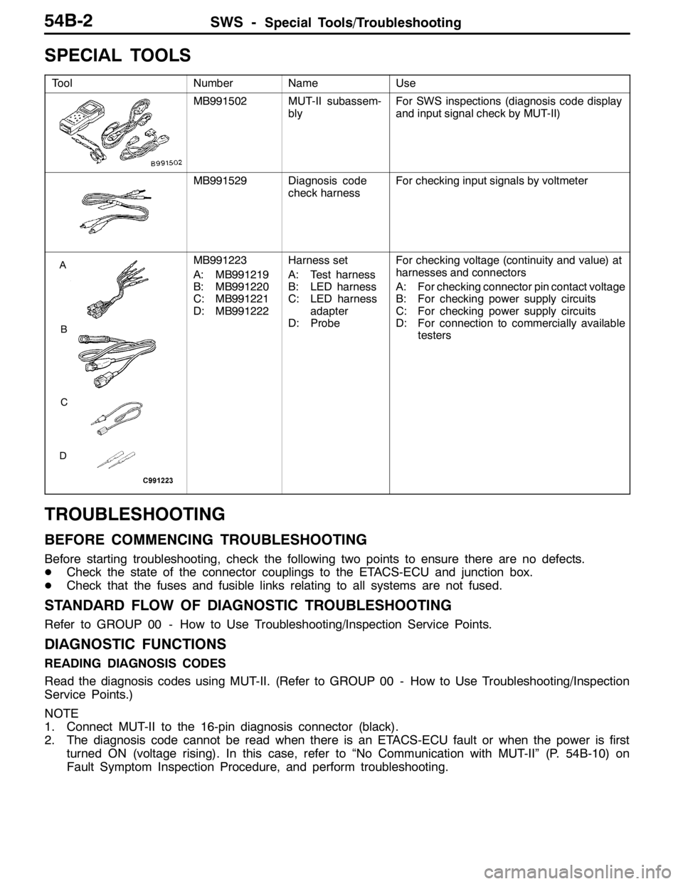
SPECIAL TOOLS
ToolNumberNameUse
MB991502MUT-II subassem-
blyFor SWS inspections (diagnosis code display
and input signal check by MUT-II)
MB991529Diagnosis code
check harnessFor checking input signals by voltmeter
A
B
C
D
MB991223
A: MB991219
B: MB991220
C: MB991221
D: MB991222Harness set
A: Test harness
B: LED harness
C: LED harness
adapter
D: ProbeFor checking voltage (continuity and value) at
harnesses and connectors
A: For checking connector pin contact voltage
B: For checking power supply circuits
C: For checking power supply circuits
D: For connection to commercially available
testers
TROUBLESHOOTING
BEFORE COMMENCING TROUBLESHOOTING
Before starting troubleshooting, check the following two points to ensure there are no defects.
DCheck the state of the connector couplings to the ETACS-ECU and junction box.
DCheck that the fuses and fusible links relating to all systems are not fused.
STANDARD FLOW OF DIAGNOSTIC TROUBLESHOOTING
Refer to GROUP 00 - How to Use Troubleshooting/Inspection Service Points.
DIAGNOSTIC FUNCTIONS
READING DIAGNOSIS CODES
Read the diagnosis codes using MUT-II. (Refer to GROUP 00 - How to Use Troubleshooting/Inspection
Service Points.)
NOTE
1. Connect MUT-II to the 16-pin diagnosis connector (black).
2. The diagnosis code cannot be read when there is an ETACS-ECU fault or when the power is first
turned ON (voltage rising). In this case, refer to “No Communication with MUT-II” (P. 54B-10) on
Fault Symptom Inspection Procedure, and perform troubleshooting.
Page 1367 of 1449

SWS -Troubleshooting54B-3
INPUT SIGNAL CHECK
1. Check the inputs using MUT-II or a voltmeter. (Refer to GROUP 00 - How to Use
Troubleshooting/Inspection Service Points.)
2. The following input signals can be checked using MUT-II or a voltmeter connected to the diagnosis
connector.
NOTE
When fault is detected during input signal inspection, refer to Trouble Symptom Chart to perform
troubleshooting. (Refer to P.54B-7).
Input Signal Check Function
Input signalBuzzer operation condition
Ignition switch (ACC)When ignition switch turned from “LOCK” (OFF)
to ACC.
Ignition switch (IG1)When ignition switch turned from “ACC” to “ON”.
Hazard warning lamp switchWhen switch turned from OFF to ON.
Rear fog lamp switch
Driver’s door switchWhen driver’s door opened from closed
All door switchesWhen any door opened when all doors were
closed.
Driver’s door lock actuatorWhen the driver’s side key cylinder or inside lock
knob is moved from the locked to unlocked
position or vice versa.
Vehicle speed signalVehicle speed changes from less than 10 km/h to
10 km/h or more.
Column switchesTail lamp switchWhen lighting switch turned from automatic
lighting to tail lamp position.
Headlamp switchWhen lighting switch turned from tail lamp to
headlamp position.
Dimmer switchWhen switch turned from OFF to ON.
Passing switch
Left-hand turn signal lamp switch
Right-hand turn signal lamp switch
Windshield mist wiper switch
Windshield wiper intermittent timing switch
Windshield wiper LO speed switch
Windshield wiper HI speed switch
Windshield washer switchWhen switch turned from OFF to ON.
Power window
main switchAll switchesWhen switch turned from OFF to ON.
DIAGNOSIS CODE CHART
Code No.Diagnosis itemReference page
11ETACS-ECU-related failure54B-4
12Column switch-related failure or fault in connecting to ETACS-ECU54B-4
13Front-ECU-related failure or fault in connecting to ETACS-ECU54B-5
21Short circuit in communication lines54B-6
Page 1368 of 1449

SWS -Troubleshooting54B-4
DIAGNOSIS CODE INSPECTION PROCEDURES
Code No. 11 ETACS-ECU-related failureProbable cause
The ETACS-ECU monitors its own communication data, outputting this diagnosis
code when data error occurs 15 consecutive times (for 0.6 seconds). The
diagnosis code output stops when the ETACS-ECU confirms that its data was
transmitted normally 15 consecutive times (for 0.6 seconds).DETACS-ECU fault
Replace ETACS-ECU.
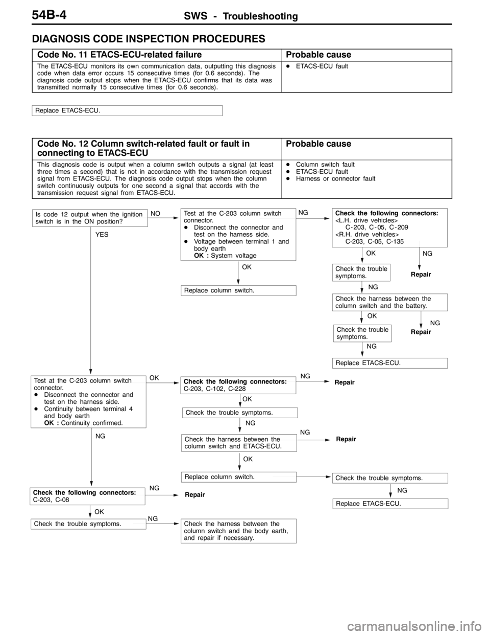
Code No. 12 Column switch-related fault or fault in
connecting to ETACS-ECUProbable cause
This diagnosis code is output when a column switch outputs a signal (at least
three times a second) that is not in accordance with the transmission request
signal from ETACS-ECU. The diagnosis code output stops when the column
switch continuously outputs for one second a signal that accords with the
transmission request signal from ETACS-ECU.DColumn switch fault
DETACS-ECU fault
DHarness or connector fault
OK
Replace column switch.
NG
Replace ETACS-ECU.
OK
Check the trouble
symptoms.
OK
Check the trouble symptoms.NGCheck the harness between the
column switch and the body earth,
and repair if necessary.
NG
Check the following connectors:
C-203, C-08NG
Repair
NG
Repair
NG
Check the harness between the
column switch and the battery.
OK
Check the trouble
symptoms.
NG
Replace ETACS-ECU.
OK
Replace column switch.Check the trouble symptoms.
NG
Check the harness between the
column switch and ETACS-ECU.NG
Repair
OK
Check the trouble symptoms.
YES
Test at the C-203 column switch
connector.
DDisconnect the connector and
test on the harness side.
DContinuity between terminal 4
and body earth
OK :Continuity confirmed.OKCheck the following connectors:
C-203, C-102, C-228NG
Repair
Is code 12 output when the ignition
switch is in the ON position?NOTest at the C-203 column switch
connector.
DDisconnect the connector and
test on the harness side.
DVoltage between terminal 1 and
body earth
OK :System voltageNGCheck the following connectors:
C - 203, C - 05, C - 209
C-203, C-05, C-135
NG
Repair
Page 1369 of 1449

SWS -Troubleshooting54B-5
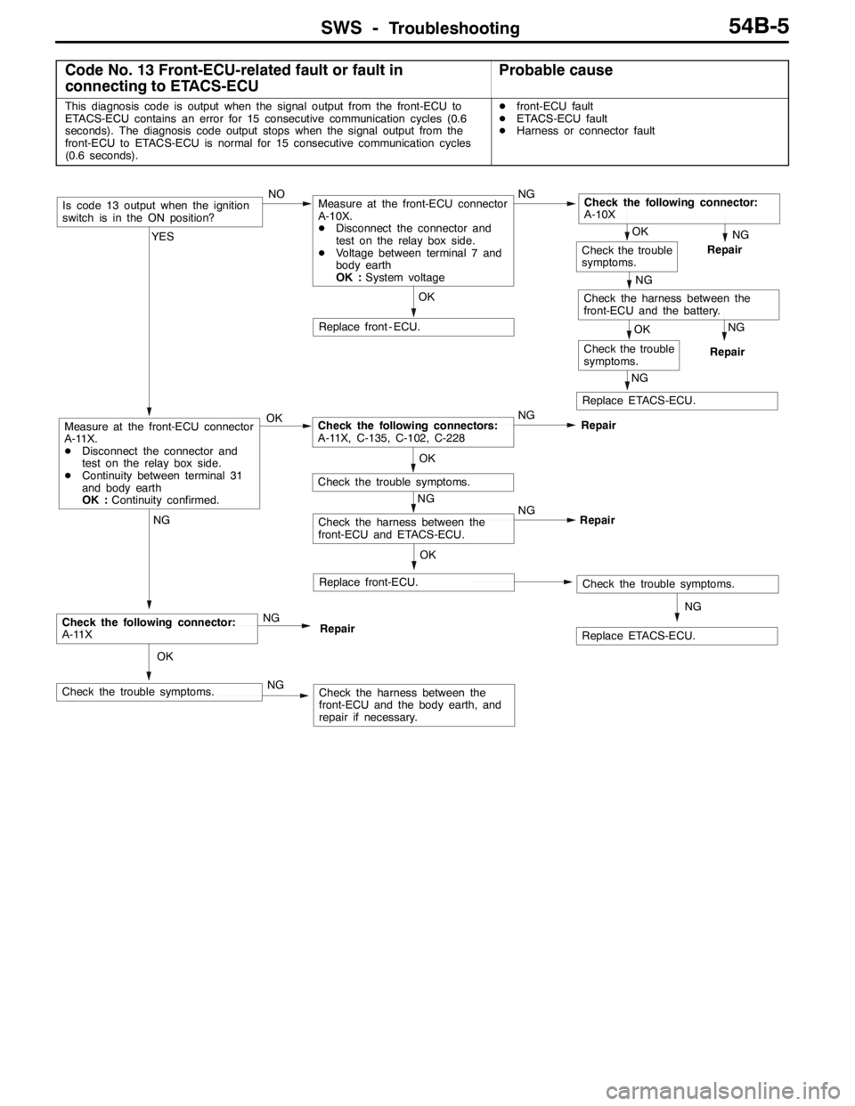
Code No. 13 Front-ECU-related fault or fault in
connecting to ETACS-ECUProbable cause
This diagnosis code is output when the signal output from the front-ECU to
ETACS-ECU contains an error for 15 consecutive communication cycles (0.6
seconds). The diagnosis code output stops when the signal output from the
front-ECU to ETACS-ECU is normal for 15 consecutive communication cycles
(0.6 seconds).Dfront-ECU fault
DETACS-ECU fault
DHarness or connector fault
NG
Repair
NG
Replace ETACS-ECU.
OK
Check the trouble
symptoms.
NG
Repair
NG
Check the harness between the
front-ECU and the battery.
OK
Check the trouble
symptoms.
NG
Replace ETACS-ECU.
OK
Replace front-ECU.Check the trouble symptoms.
NG
Check the harness between the
front-ECU and ETACS-ECU.NG
Repair
OK
Check the trouble symptoms.
OK
Replace front - ECU.
OK
Check the trouble symptoms.NGCheck the harness between the
front-ECU and the body earth, and
repair if necessary.
NG
Check the following connector:
A-11XNG
Repair
YES
Measure at the front-ECU connector
A-11X.
DDisconnect the connector and
test on the relay box side.
DContinuity between terminal 31
and body earth
OK :Continuity confirmed.OKCheck the following connectors:
A-11X, C-135, C-102, C-228NG
Repair
Is code 13 output when the ignition
switch is in the ON position?NOMeasure at the front-ECU connector
A-10X.
DDisconnect the connector and
test on the relay box side.
DVoltage between terminal 7 and
body earth
OK :System voltageNGCheck the following connector:
A-10X
Page 1370 of 1449

SWS -Troubleshooting54B-6
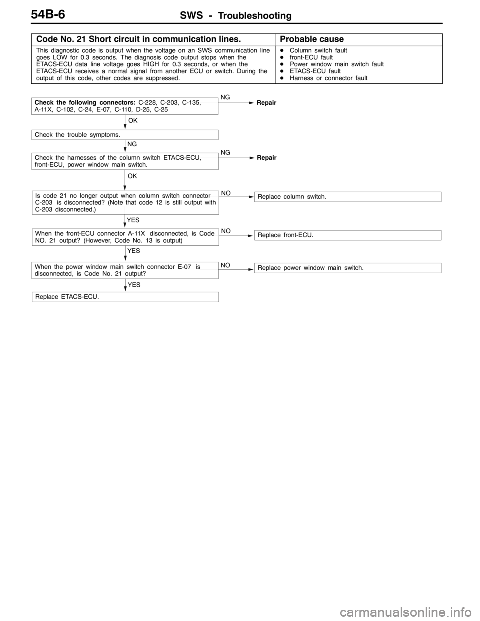
Code No. 21 Short circuit in communication lines.Probable cause
This diagnostic code is output when the voltage on an SWS communication line
goes LOW for 0.3 seconds. The diagnosis code output stops when the
ETACS-ECU data line voltage goes HIGH for 0.3 seconds, or when the
ETACS-ECU receives a normal signal from another ECU or switch. During the
output of this code, other codes are suppressed.DColumn switch fault
Dfront-ECU fault
DPower window main switch fault
DETACS-ECU fault
DHarness or connector fault
Replace ETACS-ECU.
YES
YES
When the power window main switch connector E-07 is
disconnected, is Code No. 21 output?NOReplace power window main switch.
YES
When the front-ECU connector A-11X disconnected, is Code
NO. 21 output? (However, Code No. 13 is output)NOReplace front-ECU.
OK
Is code 21 no longer output when column switch connector
C-203 is disconnected? (Note that code 12 is still output with
C-203 disconnected.)NOReplace column switch.
NG
Check the harnesses of the column switch ETACS-ECU,
front-ECU, power window main switch.NG
Repair
OK
Check the trouble symptoms.
Check the following connectors:C-228, C-203, C-135,
A-11X, C-102, C-24, E-07, C-110, D-25, C-25NG
Repair