2007 MITSUBISHI LANCER EVOLUTION ECU
[x] Cancel search: ECUPage 1392 of 1449
SWS -Troubleshooting54B-28
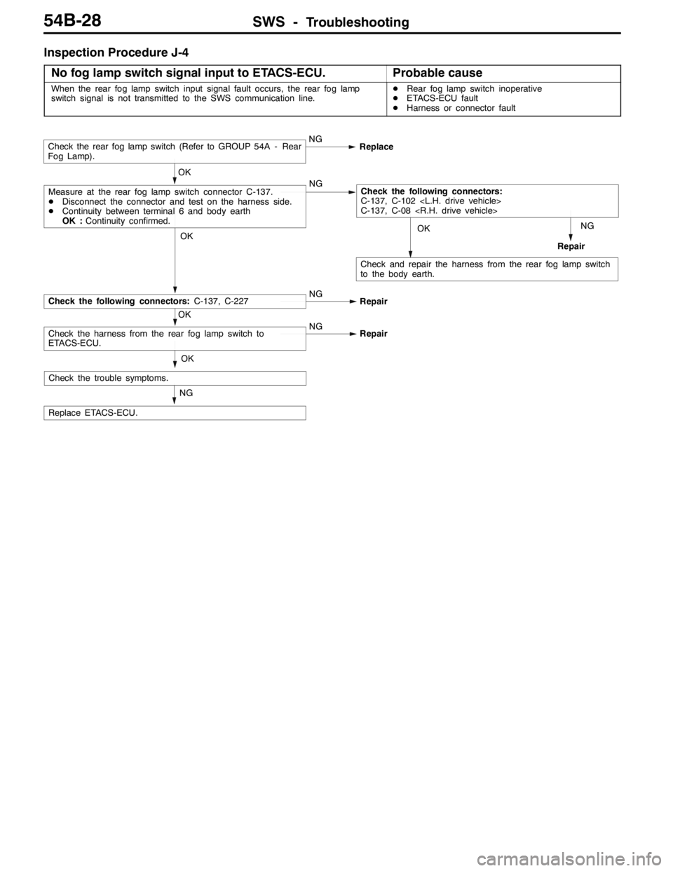
Inspection Procedure J-4
No fog lamp switch signal input to ETACS-ECU.
Probable cause
When the rear fog lamp switch input signal fault occurs, the rear fog lamp
switch signal is not transmitted to the SWS communication line.DRear fog lamp switch inoperative
DETACS-ECU fault
DHarness or connector fault
NG
RepairOK
Check and repair the harness from the rear fog lamp switch
to the body earth.
NG
Replace ETACS-ECU.
OK
OK
Check the harness from the rear fog lamp switch to
ETACS-ECU.NG
Repair
OK
Check the following connectors:C-137, C-227NG
Repair
OK
Measure at the rear fog lamp switch connector C-137.
DDisconnect the connector and test on the harness side.
DContinuity between terminal 6 and body earth
OK :Continuity confirmed.NGCheck the following connectors:
C-137, C-102
C-137, C-08
Check the rear fog lamp switch (Refer to GROUP 54A - Rear
Fog Lamp).NG
Replace
Check the trouble symptoms.
Page 1393 of 1449
SWS -Troubleshooting54B-29
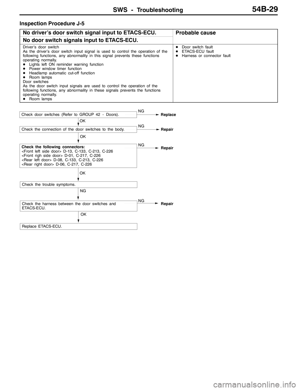
Inspection Procedure J-5
No driver’s door switch signal input to ETACS-ECU.
Probable cause
No door switch signals input to ETACS-ECU.
Driver’s door switch
As the driver’s door switch input signal is used to control the operation of the
following functions, any abnormality in this signal prevents these functions
operating normally.
DLights left ON reminder warning function
DPower window timer function
DHeadlamp automatic cut-off function
DRoom lamps
Door switches
As the door switch input signals are used to control the operation of the
following functions, any abnormality in these signals prevents the functions
operating normally.
DRoom lampsDDoor switch fault
DETACS-ECU fault
DHarness or connector fault
OK
Replace ETACS-ECU.
NG
Check the harness between the door switches and
ETACS-ECU.NG
Repair
OK
Check the trouble symptoms.
OK
Check the following connectors:
Repair
OK
Check the connection of the door switches to the body.NG
Repair
Check door switches (Refer to GROUP 42 - Doors).NG
Replace
Page 1394 of 1449
SWS -Troubleshooting54B-30
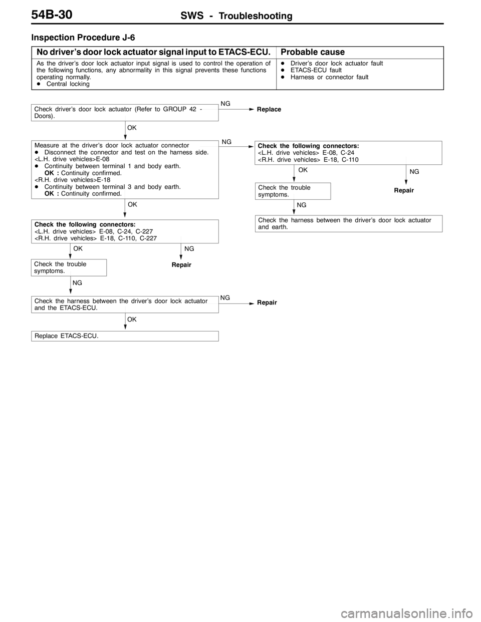
Inspection Procedure J-6
No driver’s door lock actuator signal input to ETACS-ECU.
Probable cause
As the driver’s door lock actuator input signal is used to control the operation of
the following functions, any abnormality in this signal prevents these functions
operating normally.
DCentral lockingDDriver’s door lock actuator fault
DETACS-ECU fault
DHarness or connector fault
NG
Repair
NG
Check the harness between the driver’s door lock actuator
and earth.
NG
Repair
OK
Replace ETACS-ECU.
NG
Check the harness between the driver’s door lock actuator
and the ETACS-ECU.NG
Repair
OK
Check the trouble
symptoms.
OK
Check the following connectors:
OK
Check the trouble
symptoms.
OK
Measure at the driver’s door lock actuator connector
DDisconnect the connector and test on the harness side.
DContinuity between terminal 1 and body earth.
OK :Continuity confirmed.
DContinuity between terminal 3 and body earth.
OK :Continuity confirmed.NGCheck the following connectors:
Check driver’s door lock actuator (Refer to GROUP 42 -
Doors).NG
Replace
Page 1395 of 1449
SWS -Troubleshooting54B-31
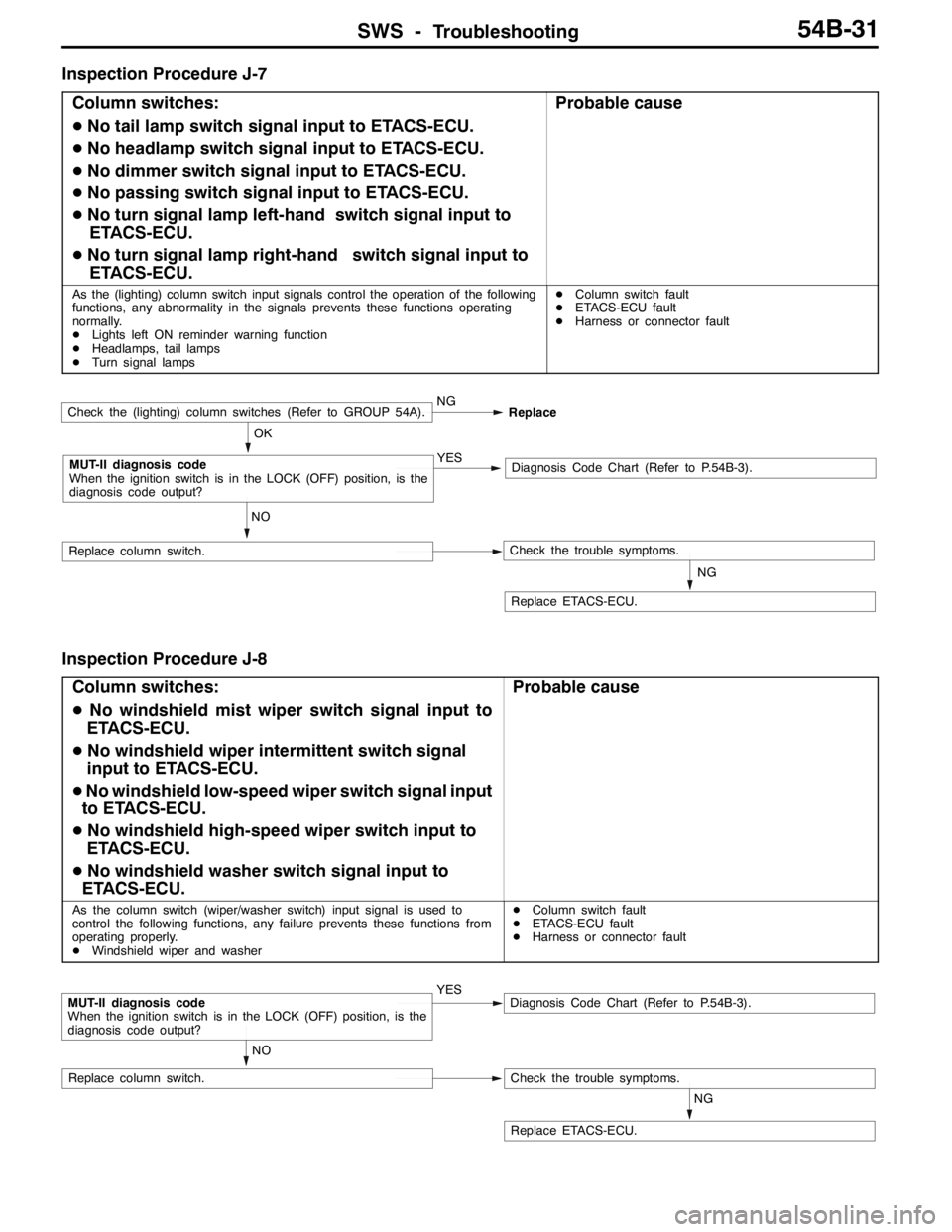
Inspection Procedure J-7
Column switches:
DNo tail lamp switch signal input to ETACS-ECU.
DNo headlamp switch signal input to ETACS-ECU.
DNo dimmer switch signal input to ETACS-ECU.
DNo passing switch signal input to ETACS-ECU.
DNo turn signal lamp left-hand switch signal input to
ETACS-ECU.
DNo turn signal lamp right-hand switch signal input to
ETACS-ECU.
Probable cause
As the (lighting) column switch input signals control the operation of the following
functions, any abnormality in the signals prevents these functions operating
normally.
DLights left ON reminder warning function
DHeadlamps, tail lamps
DTurn signal lampsDColumn switch fault
DETACS-ECU fault
DHarness or connector fault
NG
Replace ETACS-ECU.
NO
Replace column switch.Check the trouble symptoms.
OK
MUT-II diagnosis code
When the ignition switch is in the LOCK (OFF) position, is the
diagnosis code output?YESDiagnosis Code Chart (Refer to P.54B-3).
Check the (lighting) column switches (Refer to GROUP 54A).NG
Replace
Inspection Procedure J-8
Column switches:
DNo windshield mist wiper switch signal input to
ETACS-ECU.
DNo windshield wiper intermittent switch signal
input to ETACS-ECU.
DNo windshield low-speed wiper switch signal input
to ETACS-ECU.
DNo windshield high-speed wiper switch input to
ETACS-ECU.
DNo windshield washer switch signal input to
ETACS-ECU.
Probable cause
As the column switch (wiper/washer switch) input signal is used to
control the following functions, any failure prevents these functions from
operating properly.
DWindshield wiper and washerDColumn switch fault
DETACS-ECU fault
DHarness or connector fault
NG
Replace ETACS-ECU.
NO
Replace column switch.Check the trouble symptoms.
MUT-II diagnosis code
When the ignition switch is in the LOCK (OFF) position, is the
diagnosis code output?YESDiagnosis Code Chart (Refer to P.54B-3).
Page 1396 of 1449
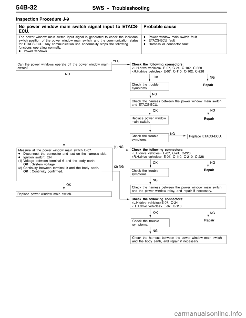
SWS -Troubleshooting54B-32
Inspection Procedure J-9
No power window main switch signal input to ETACS-
ECU.
Probable cause
The power window main switch input signal is generated to check the individual
switch position of the power window main switch, and the communication status
for ETACS-ECU. Any communication line abnormality stops the following
functions operating normally.
DPower windowsDPower window main switch fault
DETACS-ECU fault
DHarness or connector fault
Check the trouble
symptoms.NGReplace ETACS-ECU.
NG
Repair
NG
Repair
OK
Replace power window
main switch.
NG
Repair
NG
Check the harness between the power window main switch
and the power window relay, and repair if necessary.
NG
Repair
NG
Check the harness between the power window main switch
and the body earth, and repair if necessary.
OK
Replace power window main switch.
OK
Check the trouble
symptoms.
(2) NG
Check the following connectors:
OK
Check the trouble
symptoms.
NO
Measure at the power window main switch E-07.
DDisconnect the connector and test on the harness side.
DIgnition switch: ON
(1) Voltage between terminal 6 and the body earth.
OK :System voltage
(2) Continuity between terminal 9 and the body earth.
OK :Continuity confirmed.(1) NGCheck the following connectors:
NG
Check the harness between the power window main switch
and ETACS-ECU.
OK
Check the trouble
symptoms.
Can the power windows operate off the power window main
switch?YESCheck the following connectors:
Page 1397 of 1449
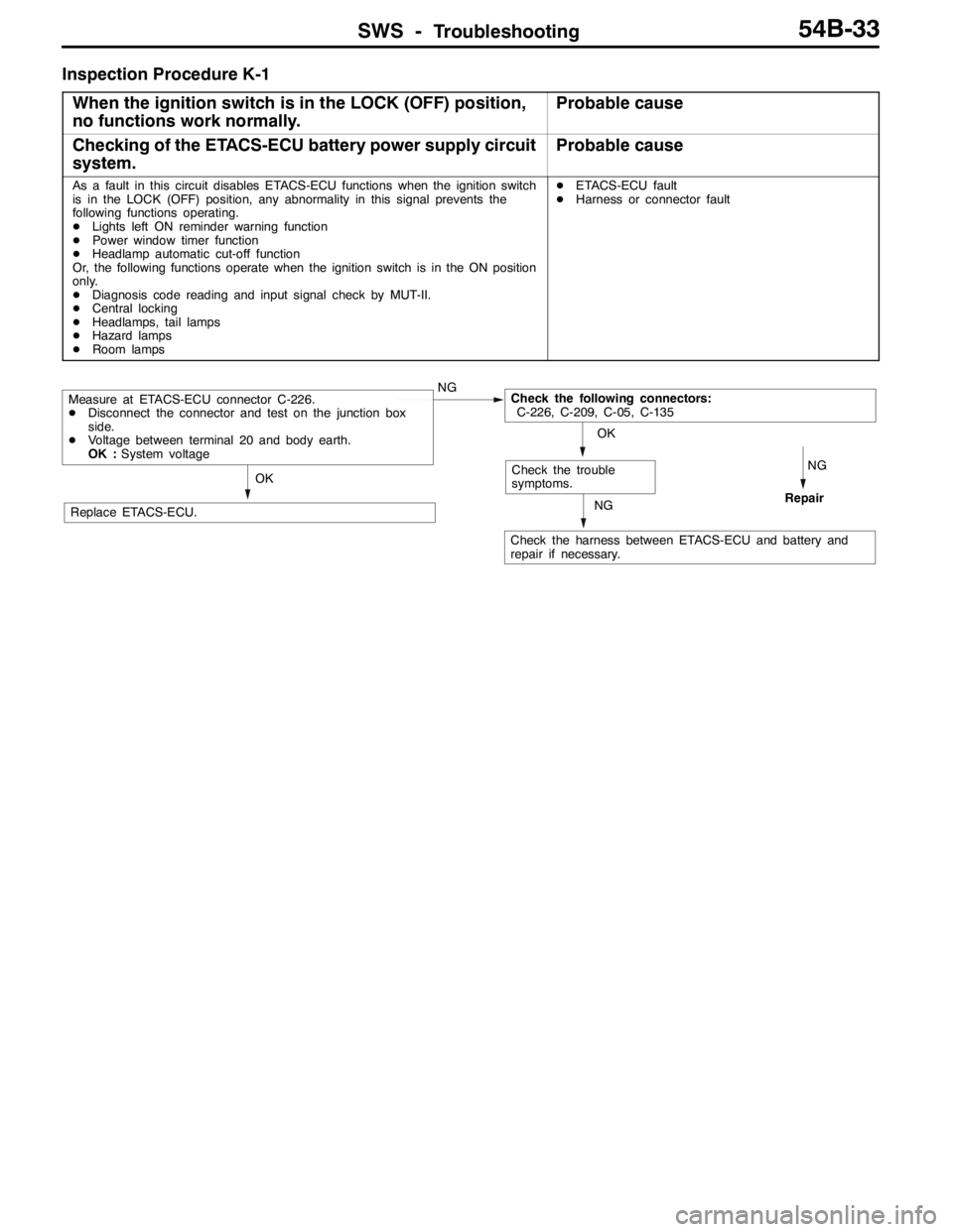
SWS -Troubleshooting54B-33
Inspection Procedure K-1
When the ignition switch is in the LOCK (OFF) position,
no functions work normally.
Probable cause
Checking of the ETACS-ECU battery power supply circuit
system.Probable cause
As a fault in this circuit disables ETACS-ECU functions when the ignition switch
is in the LOCK (OFF) position, any abnormality in this signal prevents the
following functions operating.
DLights left ON reminder warning function
DPower window timer function
DHeadlamp automatic cut-off function
Or, the following functions operate when the ignition switch is in the ON position
only.
DDiagnosis code reading and input signal check by MUT-II.
DCentral locking
DHeadlamps, tail lamps
DHazard lamps
DRoom lampsDETACS-ECU fault
DHarness or connector fault
NG
RepairNG
Check the harness between ETACS-ECU and battery and
repair if necessary.
OK
Replace ETACS-ECU.
OK
Check the trouble
symptoms.
Measure at ETACS-ECU connector C-226.
DDisconnect the connector and test on the junction box
side.
DVoltage between terminal 20 and body earth.
OK :System voltageNGCheck the following connectors:
C-226, C-209, C-05, C-135
Page 1398 of 1449

SWS -Troubleshooting54B-34
CHECKS AT ECU TERMINALS
ETACS-ECU
*
Y0795AU
NOTE
*See the list below for data on the ETACS-ECU terminal 1 - 20 connectors. As the ETACS-ECU connects
directly onto the junction box, the voltages cannot be measured.
Terminal
No.Check itemsChecking requirementsNormal condition
1Power window relay outputWhen power windows operating
normallySystem voltage
2Battery power supply (for central
locking)Any timeSystem voltage
3Earth (for ECU)Any time0V
4Ignition switch (ACC)Ignition switch: ACCSystem voltage
5Room lamp outputWhen room lamps ON2 V or below
6---
7Door switch inputWhen any one door switch ON (door
open)0V
8Ignition switch (IG1) power supplyIgnition switch: ONSystem voltage
9Right-hand turn signal lamp outputWhen right-hand turn signal lamp ONSystem voltage
10Driver’s door switch inputWhen driver’s door switch ON (door
open)0V
11Battery power supply (for hazard
lamps)Any timeSystem voltage
12Central locking (lock) outputWhen door lock actuator operating
(locking operation)System voltage
13Central locking (unlock) output (NOT
driver’s door)When door lock actuator operating
(unlocking)System voltage
14Left-hand turn signal lamp outputWhen left-hand turn signal lamp ONSystem voltage
15 - 17---
18Ignition switch (ACC) power supplyIgnition switch: ACCSystem voltage
19Battery power supply for interior lampWhen interior lamp ONSystem voltage
20Battery power supply (for ECU)Any timeSystem voltage
21Rear fog lamp switch inputWhen the rear fog lamp switch ON0V
22Central locking (unlock) output (for
driver’s door)When door lock actuator operating
(unlocking)System voltage
23---
24 - 32---
33Door lock key cylinder switch input
(unlock switch)When driver’s door lock unlocked0V
34Door lock key cylinder switch input
(lock switch)When driver’s door lock locked0V
Page 1400 of 1449

SWS -Troubleshooting54B-36
COLUMN SWITCHES
Terminal
No.Check itemChecking requirementsNormal condition
1Battery power supplyAny timeSystem voltage
2SWS request signal inputAny time0 - 12 V (pulse
signal)
3SWS communication lineAny time0 - 12 V (pulse
signal)
4EarthAny time0V
5-7---
8Windshield wiper switch backup
outputWindshield wiper low or high-speed
switch: ON0V
9Ignition switch (IG1) power supplyIgnition switch: ONSystem voltage
10Headlamp switch backup outputHeadlamp switch: ON0V
FRONT-ECU
NOTE
See the list below for data on the front-ECU terminals. As the front-ECU connects directly onto the relay
box, the voltages cannot be measured.
Terminal
No.Check itemChecking requirementsNormal condition
1---
2Headlamp (high-beam) outputWhen headlamp (high-beam) ONSystem voltage
3, 4Battery power supply (for headlamps)Any timeSystem voltage
5Battery power supply (for tail lamps)Any timeSystem voltage
6Headlamp (low-beam) outputWhen headlamp (low-beam) ONSystem voltage
7Battery power supply (for ECU)Any timeSystem voltage
8Tail lamp outputWhen tail lamps ONSystem voltage
9-11---
21Windshield washer outputWhen windshield washer operatingSystem voltage
22SWS communication lineAny time0 - 12 V (pulse
signal)
23Windshield wiper automatic STOP
signal inputWhen windshield wiper operatingSystem voltage
24Ignition switch (ACC) power supplyIgnition switch: ACCSystem voltage
25Headlamp switch backup inputHeadlamp switch: ON0V
26Windshield wiper switch backup inputWindshield wiper low or high-speed
switch: ON0V
27Windshield wiper (low-speed) outputWhen windshield wiper operating (at
low-speed)System voltage
28Windshield wiper (high-speed) outputWhen windshield wiper operating (at
high-speed)System voltage