Page 915 of 1449
MANUAL TRANSMISSION OVERHAUL -Center Differential22B-49
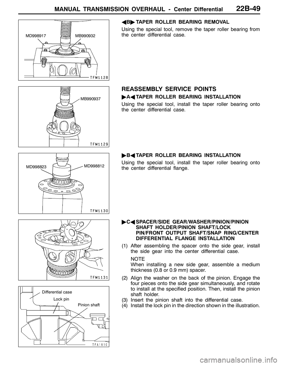
AB"TAPER ROLLER BEARING REMOVAL
Using the special tool, remove the taper roller bearing from
the center differential case.
REASSEMBLY SERVICE POINTS
"AATAPER ROLLER BEARING INSTALLATION
Using the special tool, install the taper roller bearing onto
the center differential case.
"BATAPER ROLLER BEARING INSTALLATION
Using the special tool, install the taper roller bearing onto
the center differential flange.
"CASPACER/SIDE GEAR/WASHER/PINION/PINION
SHAFT HOLDER/PINION SHAFT/LOCK
PIN/FRONT OUTPUT SHAFT/SNAP RING/CENTER
DIFFERENTIAL FLANGE INSTALLATION
(1) After assembling the spacer onto the side gear, install
the side gear into the center differential case.
NOTE
When installing a new side gear, assemble a medium
thickness (0.8 or 0.9 mm) spacer.
(2) Align the washer on the back of the pinion. Engage the
four pieces onto the side gear simultaneously, and rotate
to install at the specified position. Then, install the pinion
shaft holder.
(3) Insert the pinion shaft into the differential case.
(4) Install the lock pin in the direction shown in the illustration.
MD998917 MB990932
MB990937
MD998823MD998812
Differential case
Lock pin
Pinion shaft
Page 916 of 1449
MANUAL TRANSMISSION OVERHAUL -Center Differential22B-50
(5) Install the front output shaft onto the side gear, and install
the snap ring.
(6) After assembling the side gear into the center differential
case, install the spacer onto the side gear.
(7) Match the alignment marks, install the center differential
flange, and temporarily fix the machine screw.
(8) Measure the backlash between the side gear and pinion.
Standard value: 0.025 - 0.150 mm
(9) If the backlash is not within the standard value, select
a spacer, and measure the backlash again.
NOTE
Adjust so that the backlash on both sides is even.
"DACENTER DIFFERENTIAL DRIVE GEAR
INSTALLATION
(1) Confirm that rust-proofing oil is applied, and then apply
sealant on all of the bolt threads.
Sealant
Specified sealant:
3M STUD Locking No.4170 or equivalent
(2) Tighten with the specified torque following the order shown
in the illustration.
Page 921 of 1449
PROPELLER SHAFT - Propeller Shaft25-3
PROPELLER SHAFT
REMOVAL AND INSTALLATION
Gear Oil: Hypoid gear oil SAE 75W-90 or
75W-85W or 80W conforming to API GL-41
3 22
1
1 1
30±4 N·m
32±2 N·m 30±4 N·m
Removal steps
1. Insulator
2. Spacer
AA""AA3. Propeller shaft assembly
REMOVAL SERVICE POINT
AA"PROPELLER SHAFT ASSEMBLY REMOVAL
1. Make mating marks on the differential companion flange
and flange yoke, and then remove the front propeller
shaft assembly.
2. By filling rag in the boot and align the propeller shaft,
remove the propeller shaft assembly
Caution
If the joint part is bent, the joint boot is danger of
damage by folding joint boot.
A10C0017
Joint assembly
Center propeller
shaft
Joint bootRag
Page 947 of 1449
27B-1
REAR AXLE
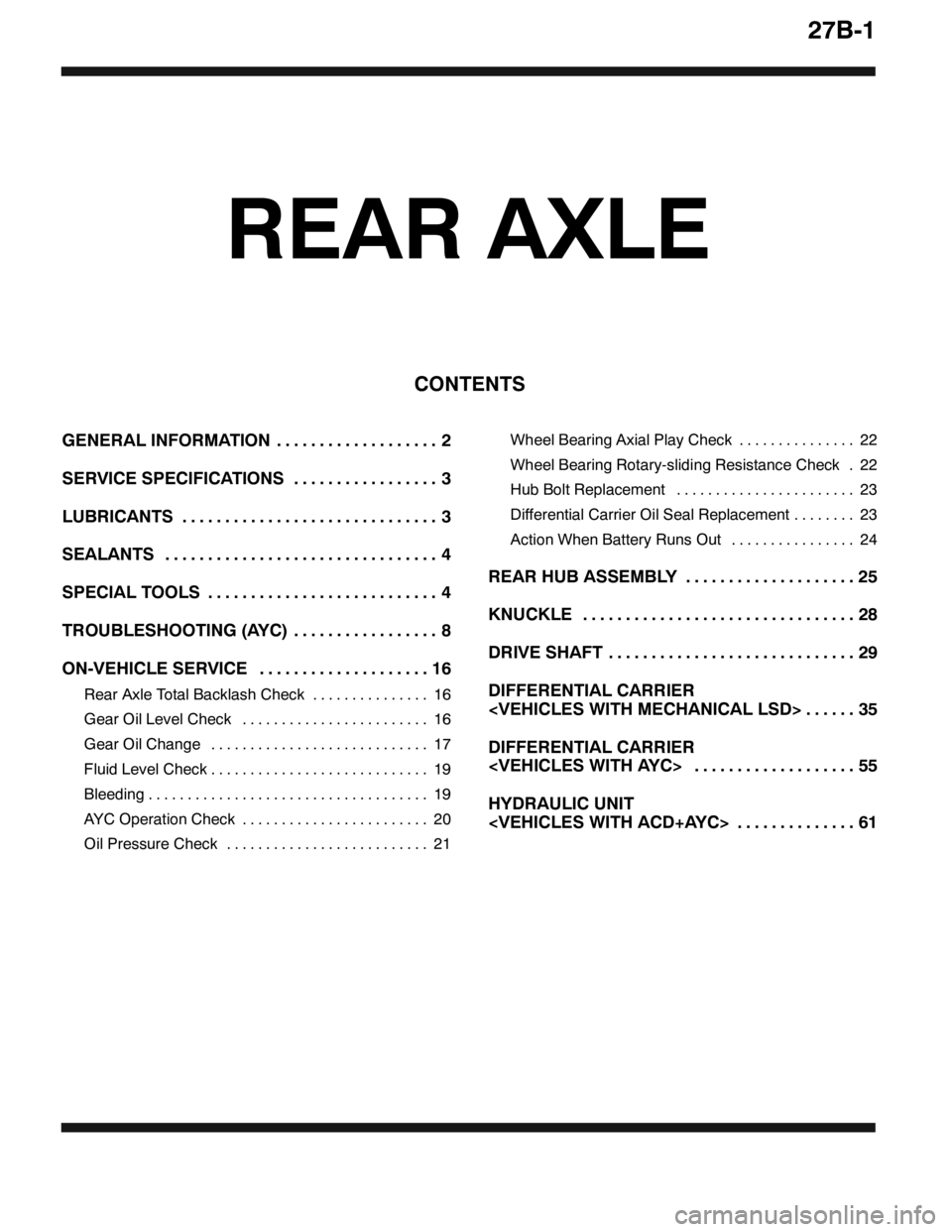
CONTENTS
GENERAL INFORMATION 2...................
SERVICE SPECIFICATIONS 3.................
LUBRICANTS 3..............................
SEALANTS 4................................
SPECIAL TOOLS 4...........................
TROUBLESHOOTING (AYC) 8.................
ON-VEHICLE SERVICE 16....................
Rear Axle Total Backlash Check 16...............
Gear Oil Level Check 16........................
Gear Oil Change 17............................
Fluid Level Check 19............................
Bleeding 19....................................
AYC Operation Check 20........................
Oil Pressure Check 21..........................Wheel Bearing Axial Play Check 22...............
Wheel Bearing Rotary-sliding Resistance Check 22.
Hub Bolt Replacement 23.......................
Differential Carrier Oil Seal Replacement 23........
Action When Battery Runs Out 24................
REAR HUB ASSEMBLY 25....................
KNUCKLE 28................................
DRIVE SHAFT 29.............................
DIFFERENTIAL CARRIER
35......
DIFFERENTIAL CARRIER
55...................
HYDRAULIC UNIT
61..............
Page 948 of 1449
REAR AXLE -General Information27B-2
GENERAL INFORMATION
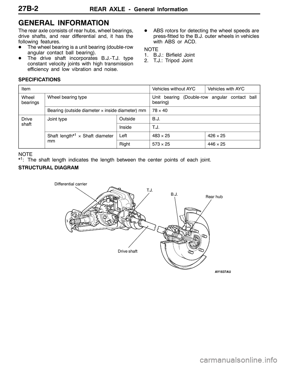
The rear axle consists of rear hubs, wheel bearings,
drive shafts, and rear differential and, it has the
following features.
DThe wheel bearing is a unit bearing (double-row
angular contact ball bearing).
DThe drive shaft incorporates B.J.-T.J. type
constant velocity joints with high transmission
efficiency and low vibration and noise.DABS rotors for detecting the wheel speeds are
press-fitted to the B.J. outer wheels in vehicles
with ABS or ACD.
NOTE
1. B.J.: Birfield Joint
2. T.J.: Tripod Joint
SPECIFICATIONS
ItemVehicles without AYCVehicles with AYC
Wheel
bearingsWheel bearing typeUnit bearing (Double-row angular contact ball
bearing)
g
Bearing (outside diameter×inside diameter) mm78×40
Drive
shaft
Joint typeOutsideB.J.
shaftInsideT.J.
Shaft length*1×Shaft diameter
mm
Left483×25426×25
mmRight573×25446×25
NOTE
*1: The shaft length indicates the length between the center points of each joint.
STRUCTURAL DIAGRAM
Oil sealRear hub Differential carrier
B.J.
Drive shaftT. J .
Page 949 of 1449
REAR AXLE -Service Specifications/Lubricants27B-3
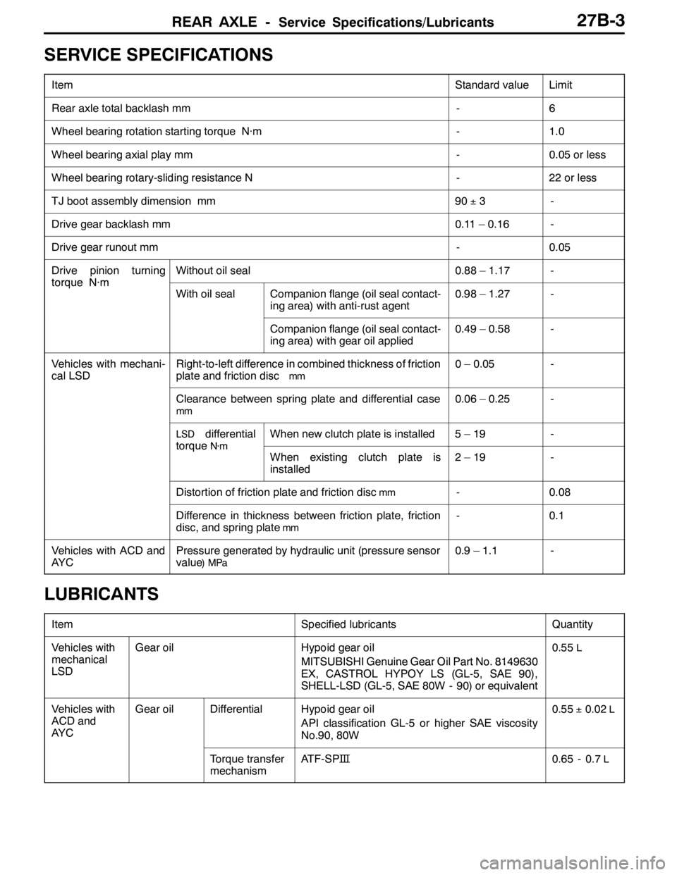
SERVICE SPECIFICATIONS
ItemStandard valueLimit
Rear axle total backlash mm-6
Wheel bearing rotation starting torque N·m-1.0
Wheel bearing axial play mm-0.05 or less
Wheel bearing rotary-sliding resistance N-22 or less
TJ boot assembly dimension mm90±3-
Drive gear backlash mm0.11 – 0.16-
Drive gear runout mm-0.05
Drive pinion turning
torqueN·m
Without oil seal0.88 – 1.17-
torqueN·m
With oil sealCompanion flange (oil seal contact-
ing area) with anti-rust agent0.98 – 1.27-
Companion flange (oil seal contact-
ing area) with gear oil applied0.49 – 0.58-
Vehicles with mechani-
cal LSDRight-to-left difference in combined thickness of friction
plate and friction disc
mm
0 – 0.05-
Clearance between spring plate and differential case
mm
0.06 – 0.25-
LSDdifferential
torqueN·m
When new clutch plate is installed5–19-
torqueN·m
When existing clutch plate is
installed2–19-
Distortion of friction plate and friction discmm-0.08
Difference in thickness between friction plate, friction
disc, and spring plate
mm
-0.1
Vehicles with ACD and
AY CPressure generated by hydraulic unit (pressure sensor
value
)MPa
0.9 – 1.1-
LUBRICANTS
ItemSpecified lubricantsQuantity
Vehicles with
mechanical
S
Gear oilHypoid gear oil
MITSUBISHI Genuine Gear Oil Part No. 81496300.55L
LSDMITSUBISHIGenuineGearOilPartNo.8149630
EX, CASTROL HYPOY LS (GL-5, SAE 90),
SHELL-LSD (GL-5, SAE 80W - 90) or equivalent
Vehicles with
ACD and
AY CGear oilDifferentialHypoid gear oil
API classification GL-5 or higher SAE viscosity
No.90, 80W0.55±0.02L
Torque transfer
mechanismATF-SP�™0.65 - 0.7L
Page 950 of 1449
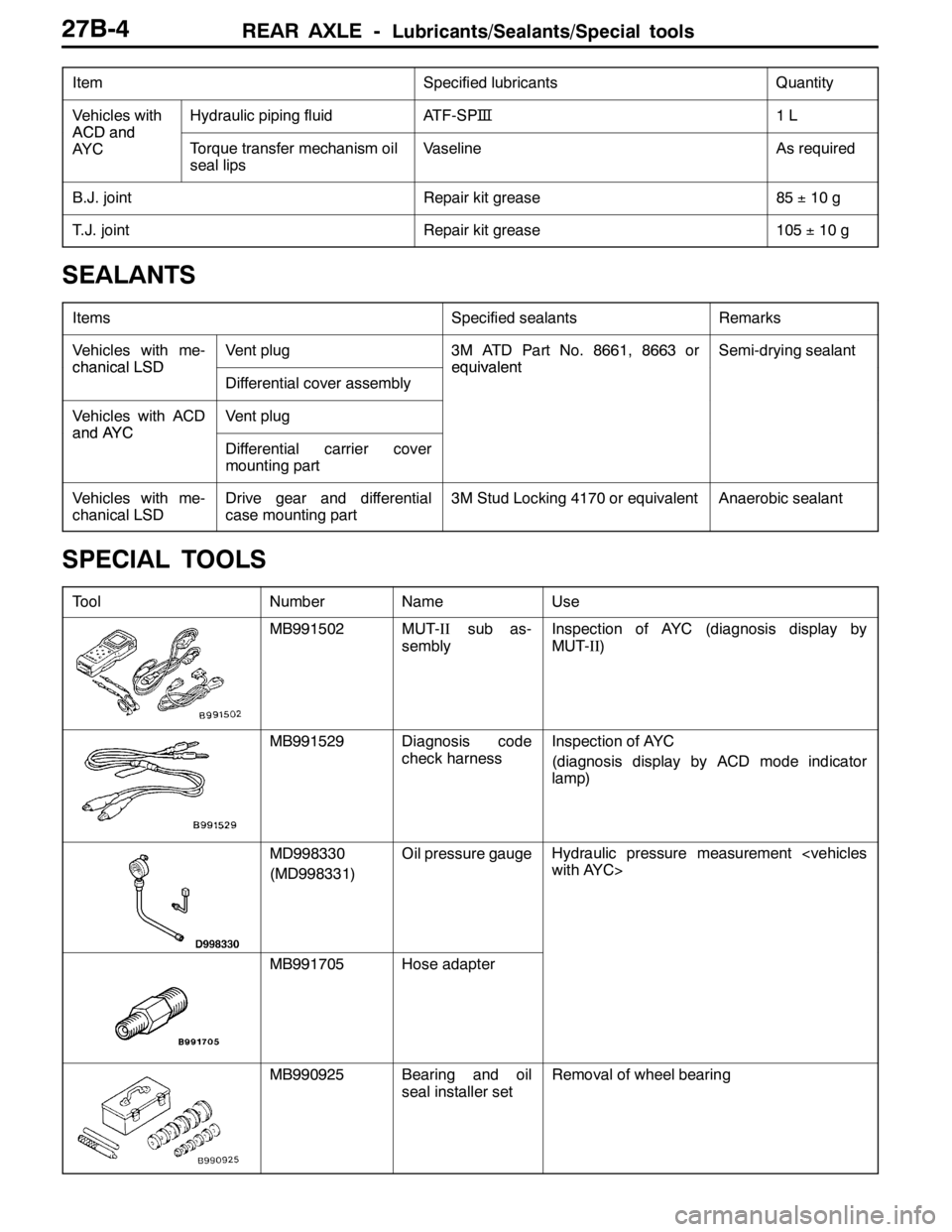
REAR AXLE -Lubricants/Sealants/Special tools27B-4
ItemQuantity Specified lubricants
Vehicles with
ACDand
Hydraulic piping fluidATF-SP�™1L
ACDand
AY CTorque transfer mechanism oil
seal lipsVaselineAs required
B.J. jointRepair kit grease85±10 g
T.J. jointRepair kit grease105±10 g
SEALANTS
ItemsSpecified sealantsRemarks
Vehicles with me-
chanicalLSD
Vent plug3M ATD Part No. 8661, 8663 or
equivalent
Semi-drying sealant
chanicalLSD
Differential cover assembly
equivalent
Vehicles with ACD
andAYC
Vent plug
andAYC
Differential carrier cover
mounting part
Vehicles with me-
chanical LSDDrive gear and differential
case mounting part3M Stud Locking 4170 or equivalentAnaerobic sealant
SPECIAL TOOLS
ToolNumberNameUse
MB991502MUT-IIsub as-
semblyInspection of AYC (diagnosis display by
MUT-II)
MB991529Diagnosis code
check harnessInspection of AYC
(diagnosis display by ACD mode indicator
lamp)
MD998330
(MD998331)Oil pressure gaugeHydraulic pressure measurement
with AYC>
MB991705Hose adapter
MB990925Bearing and oil
seal installer setRemoval of wheel bearing
Page 951 of 1449
REAR AXLE -Special Tools27B-5
Tool UseName Number
MB991115Oil seal installerPress-fitting of oil seal
(AYC differential: used in combination with
MB990938)
MD998812Installer capPress-fitting of oil seal
(torque transfer mechanism of vehicles with
AYC)
MD998813Installer100
MD998829Installer adapter
(60)
MB990767Front hub and
flange yoke holderRemoval, installation of the drive shaft nut
A
B
MB990241
A: MB990242
B: MB990244Rear axle shaft
puller
A:Puller shaft
B:Puller barDRemoval of drive shaft
DRemoval of rear hub assembly
MB991354Puller body
A
CB
00005697
A: MB991017
B: MB990998
C: MB991000A,B: Front hub re-
mover and in-
staller
C: SpacerDTemporary fixing of wheel bearing
DMeasurement of wheel bearing rotation
starting torque
DMeasurement of wheel bearing axial play
Use MB991000 (component of MB990998)
for the spacer.