Page 767 of 1449
ENGINE ELECTRICAL -Ignition System16-35
CAMSHAFT POSITION SENSOR
REMOVAL AND INSTALLATION
1 2
3
8.8±1.0 N·m
Removal steps
1. Camshaft position sensor connector
2. Camshaft position sensor
3. O-ring
CRANK ANGLE SENSOR
REMOVAL AND INSTALLATION
Caution
If the vehicle is equipped with the Brembo disc brake, during maintenance, take care not to contact
the parts or tools to the caliper because the paint of caliper will be scratched.
Pre-removal and Post-installation Operation
DCenter Cover Removal and Installation (Refer to GROUP 11A - Camshaft and Camshaft Oil Seal.)
DTiming Belt Removal and Installation (Refer to GROUP 11A.)
DReserve Tank Removal and Installation (Refer to GROUP 14 - Radiator.)
Page 810 of 1449

22A-2
MANUAL
TRANSMISSION
CONTENTS
GENERAL 3.................................
Outline of Changes 3...........................
GENERAL INFORMATION 3..................
SERVICE SPECIFICATION 3..................
LUBRICANTS 3..............................
SPECIAL TOOLS 4...........................
TROUBLESHOOTING 5...............
ON-VEHICLE SERVICE 40....................
Transmission Oil Check 40......................
Transmission Oil Replacement 40................
Transfer Oil Check 40..........................
Transfer Oil Replacement 40....................
Fluid Check
ACD and AYC> 41.............................
Bleeding
ACD and AYC> 42.............................ACD Operation Check
vehicles with ACD and AYC> 42................
Hydraulic Pressure Check
vehicles with ACD and AYC> 43................
Wheel Speed Sensor Output Voltage
Measurement
ACD and AYC> 44.............................
TRANSMISSION CONTROL* 46...............
TRANSFER ASSEMBLY 49...................
TRANSMISSION ASSEMBLY 52...............
4WD-ECU
VEHICLES WITH ACD AND AYC> 55.........
SENSOR, SWITCH AND RELAY
WITH ACD OR VEHICLES WITH ACD AND
AYC> 56.....................................
HYDRAULIC UNIT Refer to GROUP27B.......
WARNING REGARDING SERVICING OF SUPPLEMENTAL RESTRAINT SYSTEM (SRS) EQUIPPED VEHICLES
WARNING!
(1) Improper service or maintenance of any component of the SRS, or any SRS-related component, can lead to personal
injury or death to service personnel (from inadvertent firing of the air bag) or to driver and passenger (from rendering
the SRS inoperative).
(2) Service or maintenance of any SRS component or SRS-related component must be performed only at an authorized
MITSUBISHI dealer.
(3) MITSUBISHI dealer personnel must thoroughly review this manual, and especially its GROUP 52B - Supplemental
Restraint System (SRS) before beginning any service or maintenance of any component of the SRS or any SRS-related
component.
NOTE
The SRS includes the following components: SRS-ECU, SRS warning lamp, air bag module, clock spring, and interconnecting
wiring. Other SRS-related components (that may have to be removed/installed in connection with SRS service or maintenance) are
indicated in the table of contents by an asterisk (*).
Page 849 of 1449

MANUAL TRANSMISSION - On-vehicle Service22A-41
4. Fill with specified oil till the level comes to the lower portion
of oil filler plug hole.
Specified transfer oil:
MITSUBISHI Genuine Gear Oil Part No.8149630
EX, CASTROL HYPOY LS (GL-5, SAE 90),
SHELL-LSD (GL-5, SAE 80W - 90) or equivalent
Quantity:
0.55 L
ACD and AYC>
0.6 L
and AYC>
5. Tighten the oil filler plug to the specified torque.
Tightening torque: 32±2 N·m
FLUID CHECK
VEHICLES WITH ACD AND AYC>
1. Remove the maintenance lid located in the luggage
compartment.
2.
If the vehicle has been run, leave it for 90 min. or more
in an ordinary temperature (10_C–30_C) to allow the
accumulator internal pressure to drop.
NOTE
If the ambient temperature is 10_C or less, allow more
time to leave the vehicle to stand idle.
Set the MUT-IIto the 16-pin diagnosis connector. Turn ON
the ignition switch, perform MUT-IIactuator test (Item
No.03), forcibly drive the hydraulic unit and remove the
pressure in the accumulator.
Caution
Turn the ignition switch to the “LOCK”(OFF) position
before connecting or disconnecting the MUT-II.
NOTE
(1) In the actuator test (Item No. 03: Oil Level Check
Mode), the directional valve of the hydraulic unit is
moved to the left and right for 20 times, and then
the differential is cleared automatically. Drive can also
be cleared forcibly using the Clear key of the MUT-II.
(2) If the function has been stopped by fail-safe, the
hydraulic unit cannot be cleared forcibly.
3. Check that the fluid level in the oil reservoir is in the
range between MAX and MIN.
4. If the fluid level is lower than MIN, add the specified
fluid.
Specified fluid: Dia Queen ATF SP III
5. Reinstall the maintenance lid.
Page 934 of 1449

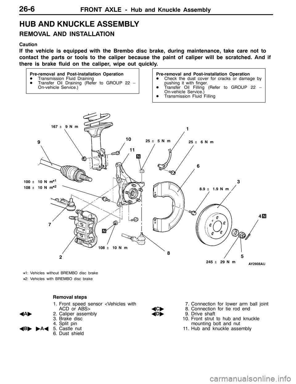
FRONT AXLE -Hub and Knuckle Assembly26-6
HUB AND KNUCKLE ASSEMBLY
REMOVAL AND INSTALLATION
Caution
If the vehicle is equipped with the Brembo disc brake, during maintenance, take care not to
contact the parts or tools to the caliper because the paint of caliper will be scratched. And if
there is brake fluid on the caliper, wipe out quickly.
Pre-removal and Post-installation Operation
DTransmission Fluid Draining
DTransfer Oil Draining (Refer to GROUP 22 –
On-vehicle Service.)Pre-removal and Post-installation Operation
DCheck the dust cover for cracks or damage by
pushing it with finger.
DTransfer Oil Filling (Refer to GROUP 22 –
On-vehicle Service.)
DTransmission Fluid Filling
25�¶5N��m
1
245�¶29 N��m
58
3
4
2
108�¶10 N��m
10
11
25�¶6N��m
6
9
100�¶10 N��m*1
108�¶10 N��m*2
167�¶9N��m
8.9�¶1.9 N��m
*1: Vehicles without BREMBO disc brake
*2: Vehicles with BREMBO disc brake
7
Removal steps
1. Front speed sensor
ACD or ABS>
AA"2. Caliper assembly
3. Brake disc
4. Split pin
AB""AA5. Castle nut
6. Dust shield7. Connection for lower arm ball joint
AC"8. Connection for tie rod end
AD"9. Drive shaft
10. Front strut to hub and knuckle
mounting bolt and nut
11. Hub and knuckle assembly
Page 935 of 1449

FRONT AXLE -Hub and Knuckle Assembly26-7
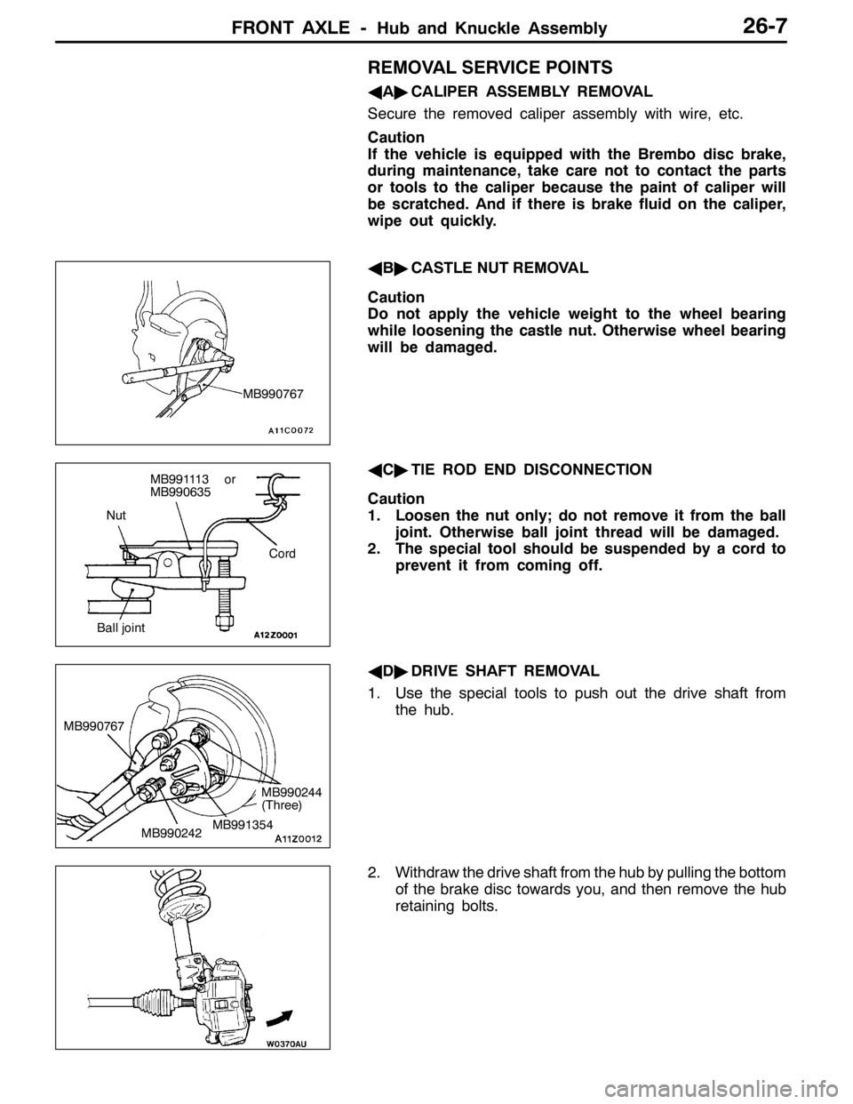
REMOVAL SERVICE POINTS
AA"CALIPER ASSEMBLY REMOVAL
Secure the removed caliper assembly with wire, etc.
Caution
If the vehicle is equipped with the Brembo disc brake,
during maintenance, take care not to contact the parts
or tools to the caliper because the paint of caliper will
be scratched. And if there is brake fluid on the caliper,
wipe out quickly.
AB"CASTLE NUT REMOVAL
Caution
Do not apply the vehicle weight to the wheel bearing
while loosening the castle nut. Otherwise wheel bearing
will be damaged.
AC"TIE ROD END DISCONNECTION
Caution
1. Loosen the nut only; do not remove it from the ball
joint. Otherwise ball joint thread will be damaged.
2. The special tool should be suspended by a cord to
prevent it from coming off.
AD"DRIVE SHAFT REMOVAL
1. Use the special tools to push out the drive shaft from
the hub.
2. Withdraw the drive shaft from the hub by pulling the bottom
of the brake disc towards you, and then remove the hub
retaining bolts.
MB990767
Nut
Cord
Ball joint
MB991113 or
MB990635
MB990242 MB990767MB991354
MB990244
(Three)
Page 938 of 1449

FRONT AXLE -Drive Shaft26-10
DRIVE SHAFT
REMOVAL AND INSTALLATION
Caution
1. If the vehicle is equipped with the Brembo disc brake, during maintenance, take care not to
contact the parts or tools to the caliper because the paint of caliper will be scratched. And
if there is brake fluid on the caliper, wipe out quickly.
2. For vehicles with ABS or ACD, do not strike the rotor for wheel speed sensor installed to
the B.J. outer race of drive shaft against other parts when removing or installing the drive
shaft. Otherwise the rotor for wheel speed sensor will be damaged.
Pre-removal and Post-installation Operation
DTransmission Fluid Draining
DTransfer Oil Draining (Refer to GROUP 22 –
On-vehicle Service.)Pre-removal and Post-installation Operation
DCheck the Dust Cover for cracks or damage by
pushing it with finger.
DTransfer Oil Filling (Refer to GROUP 22 –
On-vehicle Service.)
DTransmission Fluid Filling
1
6 9
8 5
74
3
2 11
25�¶4N��m 25�¶5N��m
245�¶29 N��m
108�¶10 N��m
10
11
39�¶5N��m
Removal steps
1. Split pin
"BA2. Castle nut
3. Front speed sensor
ABS or ACD>
4. Front speed sensor harness brack-
et
5. Brake hose bracket6. Stabilizer bar link connection
7. Lower arm ball joint connection
AA"8. Tie rod end connection
AB""AA9. Drive shaft
AC""AA10. Output shaft
11. Circlip
Page 965 of 1449

REAR AXLE -On-vehicle Service27B-19
FLUID LEVEL CHECK
1. Remove the maintenance lid located in the luggage
compartment.
2.
If the vehicle has been run, leave it for 90 min. or more
in an ordinary temperature (10_C–30_C) to allow the
accumulator internal pressure to drop.
NOTE
If the ambient temperature is 10_C or less, allow more
time to leave the vehicle to stand idle.
Set MUT-IIto 16 pin diagnostic connector. Turn the ignition
switch to the ON position, operate MUT-II, drive the
hydraulic unit (item No.03) forcibly, release the pressure in
the accumulator.
Caution
Turn the ignition switch to the LOCK (OFF) position
before connecting or disconnecting the MUT-II.
NOTE
(1) To drive (oil level check mode) forcibly, turn the
directional valve of the hydraulic unit 20 turns from
side to side, release the differential automatically.
Drive can also be cleared forcibly using the Clear
key of MUT-II.
(2) If the function has been stopped by fail safe, the
hydraulic unit can not be cleared forcibly.
3. Check that the fluid level in the oil reservoir is in the
range between MAX and MIN.
4. If the fluid level is lower than MIN, add the specified
fluid.
Specified fluid: ATF-SP III
5. Reinstall the maintenance lid.
BLEEDING
1. Lift up the vehicle.
2. Set the MUT-IIto the 16-pin diagnosis connector.
Caution
Turn the ignition switch to the LOCK (OFF) position
before connecting or disconnecting the MUT-II.
3. Turn the ignition switch to the ON position.
4. Set the steering wheel in the straight-ahead position.
5. Operating the MUT-II, drive the hydraulic unit (item No.02)
forcibly.
NOTE
(1) Drive the bleeding mode forcibly for 5 minutes, release
the operation automatically. Drive can also be cleared
forcibly using the Clear key of MUT-II.
(2) If the function has been stopped by fail safe, the
hydraulic unit cannot be cleared forcibly.
Page 971 of 1449
REAR AXLE -Rear Hub Assembly27B-25
REAR HUB ASSEMBLY
REMOVAL AND INSTALLATION
Caution
If the vehicle is equipped with the Brembo disc brake, during maintenance, take care not to contact
the parts or tools to the caliper because the paint of caliper will be scratched. And if there is
brake fluid on the caliper, wipe out quickly.
Pre-removal Operation
Gear Oil Draining (Refer to P. 27B-17.)Post-installation Operation
DGear Oil Filling (Refer to P. 27B-17.)
DParking Brake Lever Stroke Adjustment (Refer to
GROUP 36 – On-vehicle Service.)
2
118±19 N·m
4
1
3
225±25 N·m
8
7
6
5
10
9
54±5 N·m
81±6 N·m
Removal steps
AA"1. Rear brake caliper
2. Rear brake disc
3. Parking brake shoe & lining assembly
(Refer to GROUP 36 - Parking Brake
Drum.)
4. Clip5. Parking brake cable connection
6. Split pin
AB""AA7. Drive shaft nut
8. Rear drive shaft assembly
AC"9. Rear hub assembly
10. Backing plate