Page 972 of 1449
REAR AXLE -Rear Hub Assembly27B-26
REMOVAL SERVICE POINTS
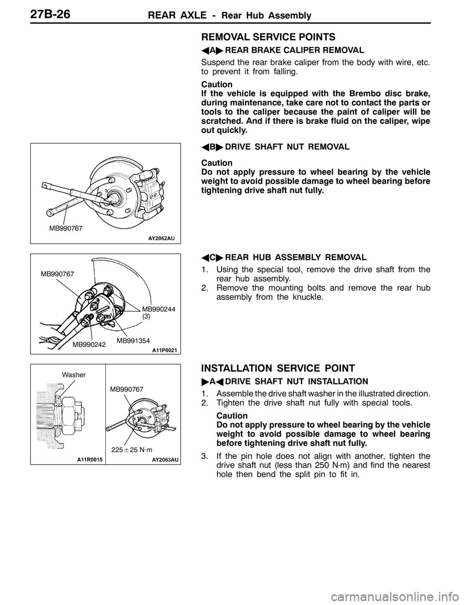
AA"REAR BRAKE CALIPER REMOVAL
Suspend the rear brake caliper from the body with wire, etc.
to prevent it from falling.
Caution
If the vehicle is equipped with the Brembo disc brake,
during maintenance, take care not to contact the parts or
tools to the caliper because the paint of caliper will be
scratched. And if there is brake fluid on the caliper, wipe
out quickly.
AB"DRIVE SHAFT NUT REMOVAL
Caution
Do not apply pressure to wheel bearing by the vehicle
weight to avoid possible damage to wheel bearing before
tightening drive shaft nut fully.
AC"REAR HUB ASSEMBLY REMOVAL
1. Using the special tool, remove the drive shaft from the
rear hub assembly.
2. Remove the mounting bolts and remove the rear hub
assembly from the knuckle.
INSTALLATION SERVICE POINT
"AADRIVE SHAFT NUT INSTALLATION
1. Assemble the drive shaft washer in the illustrated direction.
2. Tighten the drive shaft nut fully with special tools.
Caution
Do not apply pressure to wheel bearing by the vehicle
weight to avoid possible damage to wheel bearing
before tightening drive shaft nut fully.
3. If the pin hole does not align with another, tighten the
drive shaft nut (less than 250 N
·m) and find the nearest
hole then bend the split pin to fit in.
MB990767
MB990767
MB990242MB991354
MB990244
(3)
MB990767
225±25 N·m
Washer
Page 974 of 1449
REAR AXLE -Knuckle27B-28
KNUCKLE
REMOVAL AND INSTALLATION
Caution
1. If the vehicle is equipped with the Brembo disc brake, during maintenance, take care not to
contact the parts or tools to the caliper because the paint of caliper will be scratched. And
if there is brake fluid on the caliper, wipe out quickly.
2. With the part marked with *, first temporarily tighten it, then ground the vehicle and tighten
it to specification in unloaded condition.
Pre-removal Operation
Rear Hub Assembly Removal (Refer to P.27-25.)Post-installation Operation
DPress dust cover with a finger to check for crack
or damage in the dust cover.
DRear Hub Assembly Installation (Refer to P.27-25.)
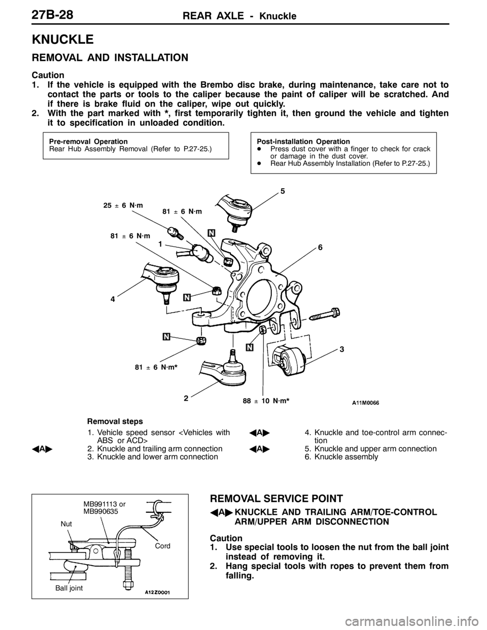
1
2
3
4
5
6
25±6 N·m81±6 N·m
81±6 N·m*
88±10 N·m*
81±6 N·m
Removal steps
1. Vehicle speed sensor
ABS or ACD>
AA"2. Knuckle and trailing arm connection
3. Knuckle and lower arm connectionAA"4. Knuckle and toe-control arm connec-
tion
AA"5. Knuckle and upper arm connection
6. Knuckle assembly
REMOVAL SERVICE POINT
AA"KNUCKLE AND TRAILING ARM/TOE-CONTROL
ARM/UPPER ARM DISCONNECTION
Caution
1. Use special tools to loosen the nut from the ball joint
instead of removing it.
2. Hang special tools with ropes to prevent them from
falling.
Nut
Cord
Ball joint
MB991113 or
MB990635
Page 975 of 1449
REAR AXLE -Drive Shaft27B-29
DRIVE SHAFT
REMOVAL AND INSTALLATION
Caution
1. If the vehicle is equipped with the Brembo disc brake, during maintenance, take care not to
contact the parts or tools to the caliper because the paint of caliper will be scratched. And
if there is brake fluid on the caliper, wipe out quickly.
2. With the part marked with *, first temporarily tighten it, then ground the vehicle and tighten
it to specification in unloaded condition.
Pre-removal Operation
DGear Oil Draining (Refer to P.27-17.)
DCenter Exhaust Pipe Removal (Refer to GROUP
15.)Post-installation Operation
DPress dust cover with a finger to check for crack
or damage in the dust cover.
DCenter Exhaust Pipe Installation (Refer to GROUP
15.)
DGear Oil Filling (Refer to P.27-17.)
DParking Brake Lever Stroke Check and Adjustment
DWheel Alignment Check and Adjustment (Refer to
GROUP 34 – On-vehicle Service.)
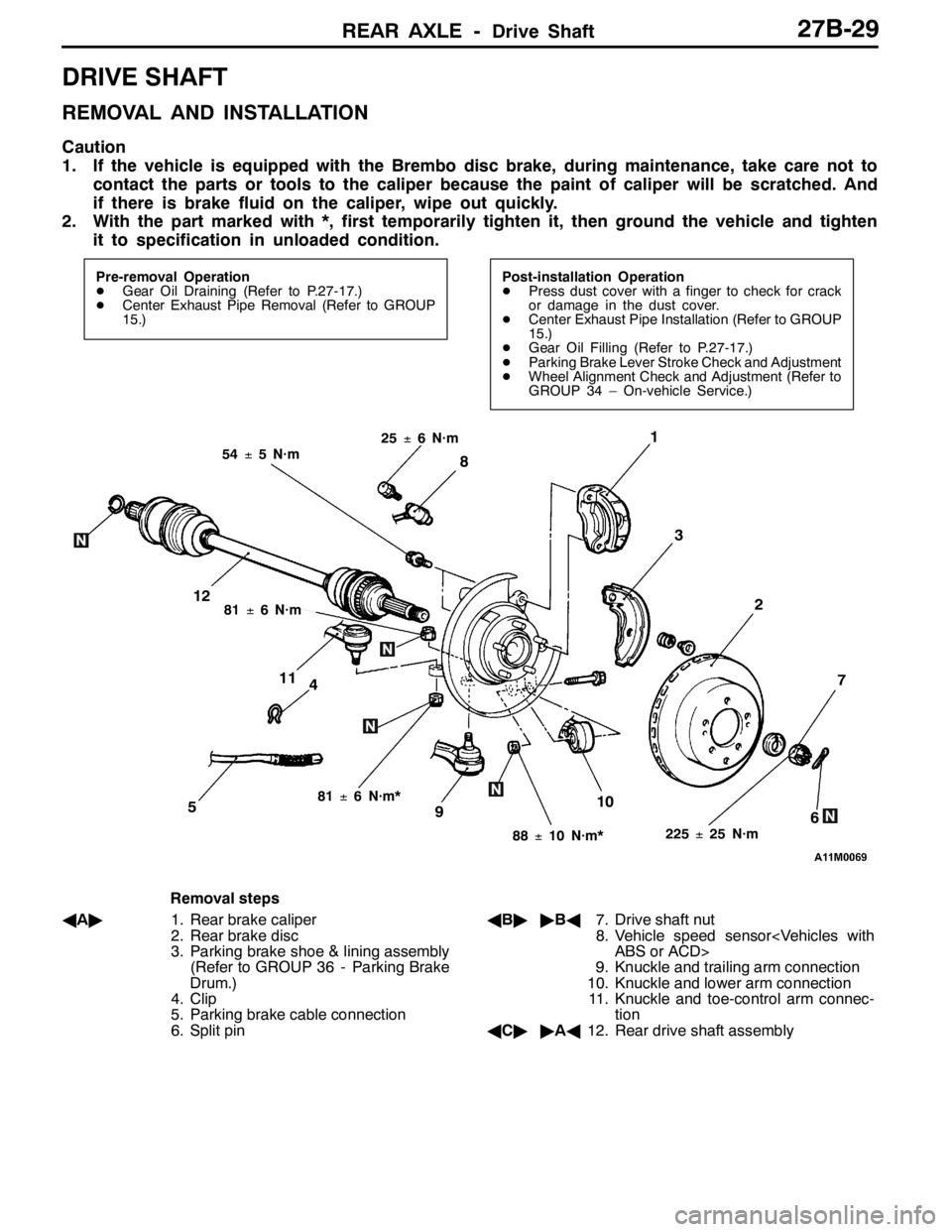
4
1
3
7
6510
2
8
9
11
12
225±25 N·m
54±5 N·m
88±10 N·m*
81±6 N·m*
81±6 N·m
25±6 N·m
Removal steps
AA"1. Rear brake caliper
2. Rear brake disc
3. Parking brake shoe & lining assembly
(Refer to GROUP 36 - Parking Brake
Drum.)
4. Clip
5. Parking brake cable connection
6. Split pinAB""BA7. Drive shaft nut
8. Vehicle speed sensor
ABS or ACD>
9. Knuckle and trailing arm connection
10. Knuckle and lower arm connection
11. Knuckle and toe-control arm connec-
tion
AC""AA12. Rear drive shaft assembly
Page 976 of 1449
REAR AXLE -Drive Shaft27B-30
REMOVAL SERVICE POINTS
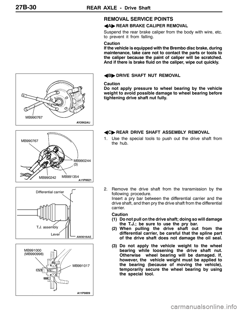
AA"REAR BRAKE CALIPER REMOVAL
Suspend the rear brake caliper from the body with wire, etc.
to prevent it from falling.
Caution
If the vehicle is equipped with the Brembo disc brake, during
maintenance, take care not to contact the parts or tools to
the caliper because the paint of caliper will be scratched.
And if there is brake fluid on the caliper, wipe out quickly.
AB"DRIVE SHAFT NUT REMOVAL
Caution
Do not apply pressure to wheel bearing by the vehicle
weight to avoid possible damage to wheel bearing before
tightening drive shaft nut fully.
AC"REAR DRIVE SHAFT ASSEMBLY REMOVAL
1. Use the special tools to push out the drive shaft from
the hub.
2. Remove the drive shaft from the transmission by the
following procedure.
Insert a pry bar between the differential carrier and the
drive shaft, and then pry the drive shaft from the differential
carrier.
Caution
(1) Do not pull on the drive shaft; doing so will damage
the T.J.; be sure to use the pry bar.
(2) When pulling the drive shaft out from the
differential carrier, be careful that the spline part
of the drive shaft does not damage the oil seal.
(3) Do not apply the vehicle weight to the wheel
bearing while loosening the drive shaft nut.
Otherwise wheel bearing will be damaged. If,
however, the vehicle weight must be applied to
the bearing (because of moving the vehicle),
temporarily secure the wheel bearing by using
the special tool.
MB990767
MB990767
MB990242MB991354
MB990244
(3)
Differential carrier
T.J. assembly
Lever
MB991017 MB991000
(MB990998)
Page 1014 of 1449
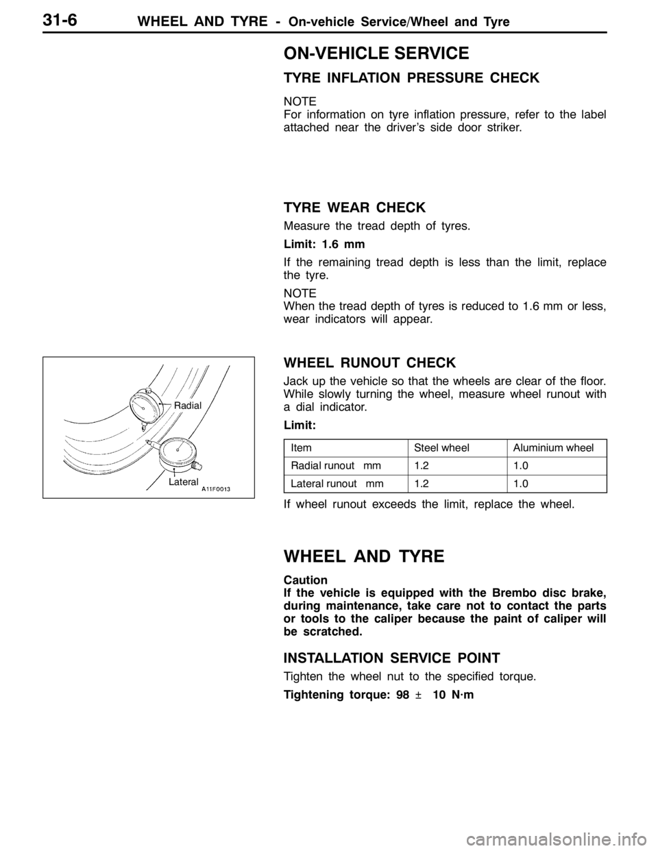
WHEEL AND TYRE -On-vehicle Service/Wheel and Tyre31-6
ON-VEHICLE SERVICE
TYRE INFLATION PRESSURE CHECK
NOTE
For information on tyre inflation pressure, refer to the label
attached near the driver’s side door striker.
TYRE WEAR CHECK
Measure the tread depth of tyres.
Limit: 1.6 mm
If the remaining tread depth is less than the limit, replace
the tyre.
NOTE
When the tread depth of tyres is reduced to 1.6 mm or less,
wear indicators will appear.
WHEEL RUNOUT CHECK
Jack up the vehicle so that the wheels are clear of the floor.
While slowly turning the wheel, measure wheel runout with
a dial indicator.
Limit:
ItemSteel wheelAluminium wheel
Radial runout mm1.21.0
Lateral runout mm1.21.0
If wheel runout exceeds the limit, replace the wheel.
WHEEL AND TYRE
Caution
If the vehicle is equipped with the Brembo disc brake,
during maintenance, take care not to contact the parts
or tools to the caliper because the paint of caliper will
be scratched.
INSTALLATION SERVICE POINT
Tighten the wheel nut to the specified torque.
Tightening torque: 98�¶10 N·m
Radial
Lateral
Page 1015 of 1449

32-1
POWER PLANT
MOUNT
CONTENTS
GENERAL INFORMATION 2..................
SPECIAL TOOL 3............................
ENGINE MOUNTING 4........................TRANSMISSION MOUNTING 5................
ENGINE ROLL STOPPER, CENTERMEMBER
6 ............................................
CROSSMEMBER* 8..........................
WARNING REGARDING SERVICING OF SUPPLEMENTAL RESTRAINT SYSTEM (SRS) EQUIPPED VEHICLES
WARNING!
(1) Improper service or maintenance of any component of the SRS, or any SRS-related component, can lead to personal
injury or death to service personnel (from inadvertent firing of the air bag) or to driver and passenger (from rendering
the SRS inoperative).
(2) Service or maintenance of any SRS component or SRS-related component must be performed only at an authorized
MITSUBISHI dealer.
(3) MITSUBISHI dealer personnel must thoroughly review this manual, and especially its GROUP 52B - Supplemental
Restraint System (SRS) before beginning any service or maintenance of any component of the SRS or any SRS-related
component.
NOTE
The SRS includes the following components: SRS-ECU, SRS warning lamp, air bag module, clock spring, and interconnecting
wiring. Other SRS-related components (that may have to be removed/installed in connection with SRS service or maintenance) are
indicated in the table of contents by an asterisk (*).
Page 1022 of 1449

POWER PLANT MOUNT - Crossmember32-8
CROSSMEMBER
REMOVAL AND INSTALLATION
Caution
1. Before removing the steering wheel and air bag module assembly, always refer to GROUP
52B - Service Precautions, Air bag Module and Clock Spring. Also, set the front wheels so
that they are facing straight forward, and remove the ignition key. If you fail to do this, the
SRS clock spring will be damaged, causing the SRS air bag to be inoperative and serious
injury.
2. *
1: Indicates parts which should be initially tightened, and then fully tightened after placing
the vehicle horizontally and loading the full weight of the engine on the vehicle body.
3. *
2: Indicates parts which should be temporarily tightened, and then fully tightened with the
vehicle on the ground in the unladen condition.
Caution
If the vehicle is equipped the Brembo disc brake, during maintenance, take care not to contact
the parts or tools to the caliper because the paint of caliper will be scratched.
Pre-removal Operations
DUnder Cover Removal
(Refer to GROUP 51 - Front Bumper.)
DCentermember, Crossmember Bar Removal
(Refer to P.32-6.)
DFront Exhaust Pipe Removal
(Refer to GROUP 15.)
DSteering Wheel Air Bag Module Assembly Removal
(Refer to GROUP 37A.)
DPower Steering Fluid Draining
(Refer to GROUP 37A - On-vehicle Service.)Post-installation Operations
DCentermember, Crossmember Bar Installation
(Refer to P.32-6.)
DFront Exhaust Pipe Installation
(Refer to GROUP 15.)
DSteering Wheel Air Bag Module Assembly
Installation (Refer to GROUP 37A.)
DPower Steering Fluid Supplying
(Refer to GROUP 37A - On-vehicle Service.)
DPower Steering Fluid Line Bleeding
(Refer to GROUP 37A - On-vehicle Service.)
DPress the dust cover with a finger to check whether
the dust cover is cracked or damaged.
DChecking Steering Wheel Position with Wheels
Straight Ahead
DFront Wheel Alignment Check and Adjustment
(Refer to GROUP 37A - On-vehicle Service.)
DUnder Cover Installation
(Refer to GROUP 51 - Front Bumper.)
Page 1035 of 1449
FRONT SUSPENSION -Lower Arm Assembly33A-9
LOWER ARM ASSEMBLY
REMOVAL AND INSTALLATION
Caution
1. If the vehicle is equipped with the Brembo disc brake, during maintenance, take care not to
contact the parts or tools to the caliper because the paint of caliper will be scratched. And
if there is brake fluid on the caliper, wipe out quickly.
2. *: To prevent bushings from breakage, the parts indicated by * should be temporarily tightened,
and then fully tightened with the vehicle on the ground in the unladen condition.
Post-installation Operation
DCheck the dust cover for cracks or damage by
pushing it with finger.
DWheel alignment check and adjustment
(Refer to P.33A-4.)
72
5
186±10 N·m*
3167±9N·m
5
1
3
4
108±10 N·m
39±5N·m
39±5N·m
Removal steps
1. Stabilizer link nut
2. Lower arm and knuckle connection
AA"3. Lower arm and crossmember
connection4. Stabilizer bracket
5. Lower arm assembly