Page 944 of 1449

FRONT AXLE -Drive Shaft26-16
(2) The adjusting bolt should not be turned more than
once.
6. Install the boot band (small) in order to create clearance as
A and B in the illustration.
7. Use the special tool to crimp the B.J. boot band (small).
Caution
(1) Secure the drive shaft in an upright position and
clamp the part of the B.J. boot band to be crimped
securely in the jaws of the special tool.
(2) Crimp the B.J. boot band until the special tool
touches the stopper.
8. Check that the crimping amount (C) of the B.J. boot band
is at the standard value.
Standard value (C): 2.4 - 2.8 mm
Readjust the value of (W) in step 5 according
to the following formula, and then repeat the
operation in step 7.
W = 5.5 mm - C
Example: If C = 2.9 mm, then W = 2.6 mm.
Remove the B.J. boot band, readjust the value
of (W) in step 5 according to the following
formula, and then repeat the operations in
steps 6 and 7 using a new B.J. boot band.
W = 5.5 mm - C
Example: If C = 2.3 mm, then W = 3.2 mm.
9. Check that the B.J. boot band is not sticking out past
the place where it has been installed.
If the B.J. boot band is sticking out, remove it and then
repeat the operations in steps 6 to 8 using a new B.J.
boot band.
B.J. boot
B.J. boot band
(small)
Projection
A
B
MB991561
C
Page 945 of 1449
FRONT AXLE -Drive Shaft26-17
10. Fill the inside of the B.J. boot with the specified amount
of the specified grease.
Specified grease: Repair kit grease
Amount to use: 110±10 g
Caution
The drive shaft joint uses special grease. Do not mix
old and new or different types of grease.
11. Install the groove in the center of the large diameter part of
the resin boot by fitting to the groove of the shaft.
12. Follow the same procedure as in step 5 to adjust the
size of the opening (W) on the special tool so that it
is at the standard value.
Standard value (W): 3.2 mm
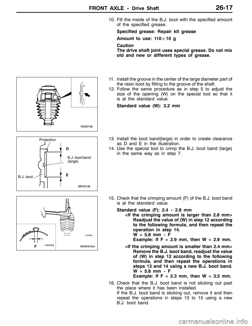
13. Install the boot band(large) in order to create clearance
as D and E in the illustration.
14. Use the special tool to crimp the B.J. boot band (large)
in the same way as in step 7.
15. Check that the crimping amount (F) of the B.J. boot band
is at the standard value.
Standard value (F): 2.4 - 2.8 mm
Readjust the value of (W) in step 12 according
to the following formula, and then repeat the
operation in step 14.
W = 5.8 mm - F
Example: If F = 2.9 mm, then W = 2.9 mm.
Remove the B.J. boot band, readjust the value
of (W) in step 12 according to the following
formula, and then repeat the operations in
steps 13 and 14 using a new B.J. boot band.
W = 5.8 mm - F
Example: If F = 2.3 mm, then W = 3.5 mm.
16. Check that the B.J. boot band is not sticking out past
the place where it has been installed.
If the B.J. boot band is sticking out, remove it and then
repeat the operations in steps 13 to 15 using a new
B.J. boot band.
B.J. boot
Projection
B.J. boot band
(large)
D
E
F
Page 949 of 1449
REAR AXLE -Service Specifications/Lubricants27B-3
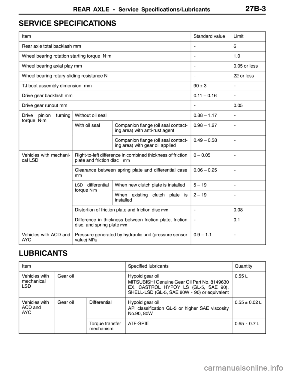
SERVICE SPECIFICATIONS
ItemStandard valueLimit
Rear axle total backlash mm-6
Wheel bearing rotation starting torque N·m-1.0
Wheel bearing axial play mm-0.05 or less
Wheel bearing rotary-sliding resistance N-22 or less
TJ boot assembly dimension mm90±3-
Drive gear backlash mm0.11 – 0.16-
Drive gear runout mm-0.05
Drive pinion turning
torqueN·m
Without oil seal0.88 – 1.17-
torqueN·m
With oil sealCompanion flange (oil seal contact-
ing area) with anti-rust agent0.98 – 1.27-
Companion flange (oil seal contact-
ing area) with gear oil applied0.49 – 0.58-
Vehicles with mechani-
cal LSDRight-to-left difference in combined thickness of friction
plate and friction disc
mm
0 – 0.05-
Clearance between spring plate and differential case
mm
0.06 – 0.25-
LSDdifferential
torqueN·m
When new clutch plate is installed5–19-
torqueN·m
When existing clutch plate is
installed2–19-
Distortion of friction plate and friction discmm-0.08
Difference in thickness between friction plate, friction
disc, and spring plate
mm
-0.1
Vehicles with ACD and
AY CPressure generated by hydraulic unit (pressure sensor
value
)MPa
0.9 – 1.1-
LUBRICANTS
ItemSpecified lubricantsQuantity
Vehicles with
mechanical
S
Gear oilHypoid gear oil
MITSUBISHI Genuine Gear Oil Part No. 81496300.55L
LSDMITSUBISHIGenuineGearOilPartNo.8149630
EX, CASTROL HYPOY LS (GL-5, SAE 90),
SHELL-LSD (GL-5, SAE 80W - 90) or equivalent
Vehicles with
ACD and
AY CGear oilDifferentialHypoid gear oil
API classification GL-5 or higher SAE viscosity
No.90, 80W0.55±0.02L
Torque transfer
mechanismATF-SP�™0.65 - 0.7L
Page 978 of 1449
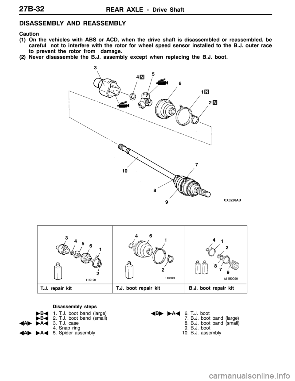
REAR AXLE -Drive Shaft27B-32
DISASSEMBLY AND REASSEMBLY
Caution
(1) On the vehicles with ABS or ACD, when the drive shaft is disassembled or reassembled, be
careful not to interfere with the rotor for wheel speed sensor installed to the B.J. outer race
to prevent the rotor from damage.
(2) Never disassemble the B.J. assembly except when replacing the B.J. boot.
2
6
4
3
5
7
1
4
2
43
61
2
4
51
2
9
10
1
8
8
97
6
T.J. repair kitT.J. boot repair kit B.J. boot repair kit
Disassembly steps
"BA1. T.J. boot band (large)
"BA2. T.J. boot band (small)
AA""AA3. T.J. case
4. Snap ring
AA""AA5. Spider assemblyAB""AA6. T.J. boot
7. B.J. boot band (large)
8. B.J. boot band (small)
9. B.J. boot
10. B.J. assembly
Page 979 of 1449
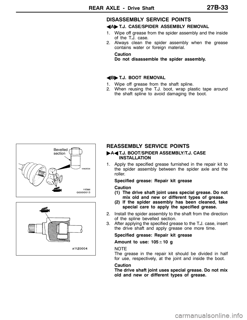
REAR AXLE -Drive Shaft27B-33
DISASSEMBLY SERVICE POINTS
AA"T.J. CASE/SPIDER ASSEMBLY REMOVAL
1. Wipe off grease from the spider assembly and the inside
of the T.J. case.
2. Always clean the spider assembly when the grease
contains water or foreign material.
Caution
Do not disassemble the spider assembly.
AB"T.J. BOOT REMOVAL
1. Wipe off grease from the shaft spline.
2. When reusing the T.J. boot, wrap plastic tape around
the shaft spline to avoid damaging the boot.
REASSEMBLY SERVICE POINTS
"AAT.J. BOOT/SPIDER ASSEMBLY/T.J. CASE
INSTALLATION
1. Apply the specified grease furnished in the repair kit to
the spider assembly between the spider axle and the
roller.
Specified grease: Repair kit grease
Caution
(1) The drive shaft joint uses special grease. Do not
mix old and new or different types of grease.
(2) If the spider assembly has been cleaned, take
special care to apply the specified grease.
2. Install the spider assembly to the shaft from the direction
of the spline bevelled section.
3. After applying the specified grease to the T.J. case, insert
the drive shaft and apply grease one more time.
Specified grease: Repair kit grease
Amount to use: 105±10 g
NOTE
The grease in the repair kit should be divided in half
for use, respectively, at the joint and inside the boot.
Caution
The drive shaft joint uses special grease. Do not mix
old and new or different types of grease.Bevelled
section
Page 980 of 1449
REAR AXLE -Drive Shaft27B-34
"BAT.J. BOOT BAND (SMALL)/T.J. BOOT BAND
(LARGE) INSTALLATION
Set the T.J. boot bands at the specified distance in order
to adjust the amount of air inside the T.J. boot, and then
tighten the T.J. boot bands securely.
Standard value (A): 90±3mm
INSPECTION
DCheck the drive shaft for damage, bending or corrosion.
DCheck the drive shaft spline part for wear or damage.
DCheck the spider assembly for roller rotation, wear or
corrosion.
DCheck the groove inside T.J. case for wear or corrosion.
DCheck the boots for deterioration, damage or cracking.
DCheck the dust cover for damage or deterioration.
B.J. BOOT (RESIN BOOT) REPLACEMENT
Refer to GROUP26 Front Axle-Drive shaft.
A
Page 981 of 1449

REAR AXLE -Differential Carrier 27B-35
DIFFERENTIAL CARRIER
REMOVAL AND INSTALLATION
Pre-removal Operation
DDifferential Gear Oil Draining (Refer to P.27B-17.)
DLower Arm Assembly Removal (Refer to GROUP
34.)
DRear Stabilizer Removal (Refer to GROUP 34.)
DDrive Shaft Removal (Refer to P. 27B-29.)Post-installation Operation
DDrive Shaft Installation (Refer to P. 27B-29.)
DRear Stabilizer Installation (Refer to GROUP 34.)
DLower Arm Assembly Installation (Refer to GROUP
34.)
DDifferential Gear Oil Filling (Refer to P.27B-17.)
12
765
4 8 910
32�¶2Nm
2
3
3 3
3
76
9
120±10 N·m
88±10 N·m
69±9 N·m
88±10 N·m
88±10 N·m
88±10 N·m
120±10 N·m
120±10 N·m
120±10 N·m
69±9 N·m
88±10 N·m
Removal steps
AA"1. Propeller shaft connection (Refer to
GROUP 25.)
2. Toe control bar
3. Differential support member mount-
ing boots and nuts
AB""AA4. Rear crossmember and differential
carrier assembly5. Differential support member
6. Upper stopper
7. Lower stopper
8. Differential support arm
9. Differential mount bracket
10. Differential carrier assembly
Page 1048 of 1449
BASIC BRAKE SYSTEM -Lubricants/Sealant/Special Tools35A-6
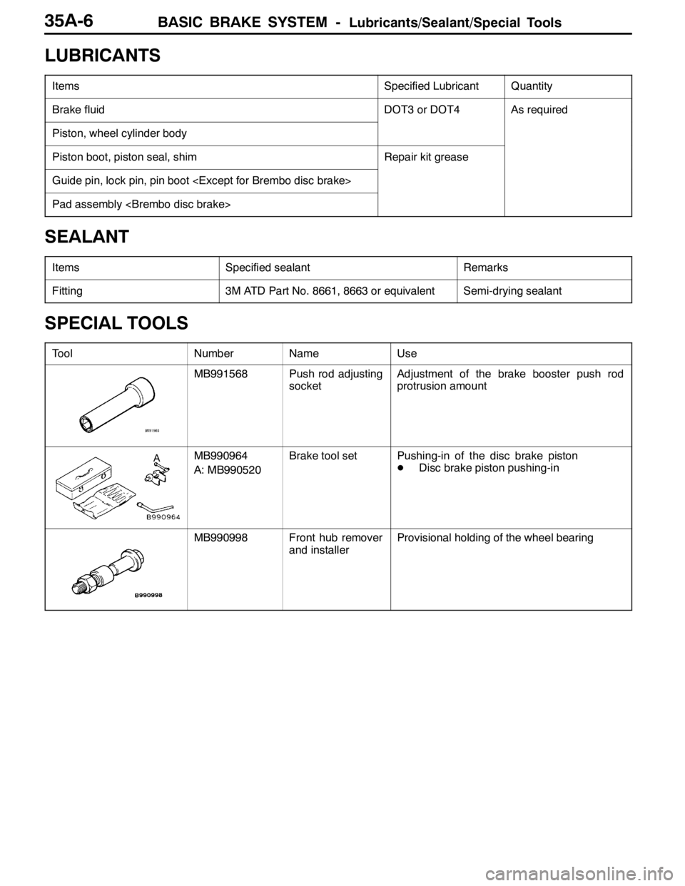
LUBRICANTS
ItemsSpecified LubricantQuantity
Brake fluidDOT3 or DOT4As required
Piston, wheel cylinder body
Piston boot, piston seal, shimRepair kit grease
Guide pin, lock pin, pin boot
Pad assembly
SEALANT
ItemsSpecified sealantRemarks
Fitting3M ATD Part No. 8661, 8663 or equivalentSemi-drying sealant
SPECIAL TOOLS
ToolNumberNameUse
MB991568Push rod adjusting
socketAdjustment of the brake booster push rod
protrusion amount
AMB990964
A: MB990520Brake tool setPushing-in of the disc brake piston
DDisc brake piston pushing-in
MB990998Front hub remover
and installerProvisional holding of the wheel bearing