Page 440 of 1449
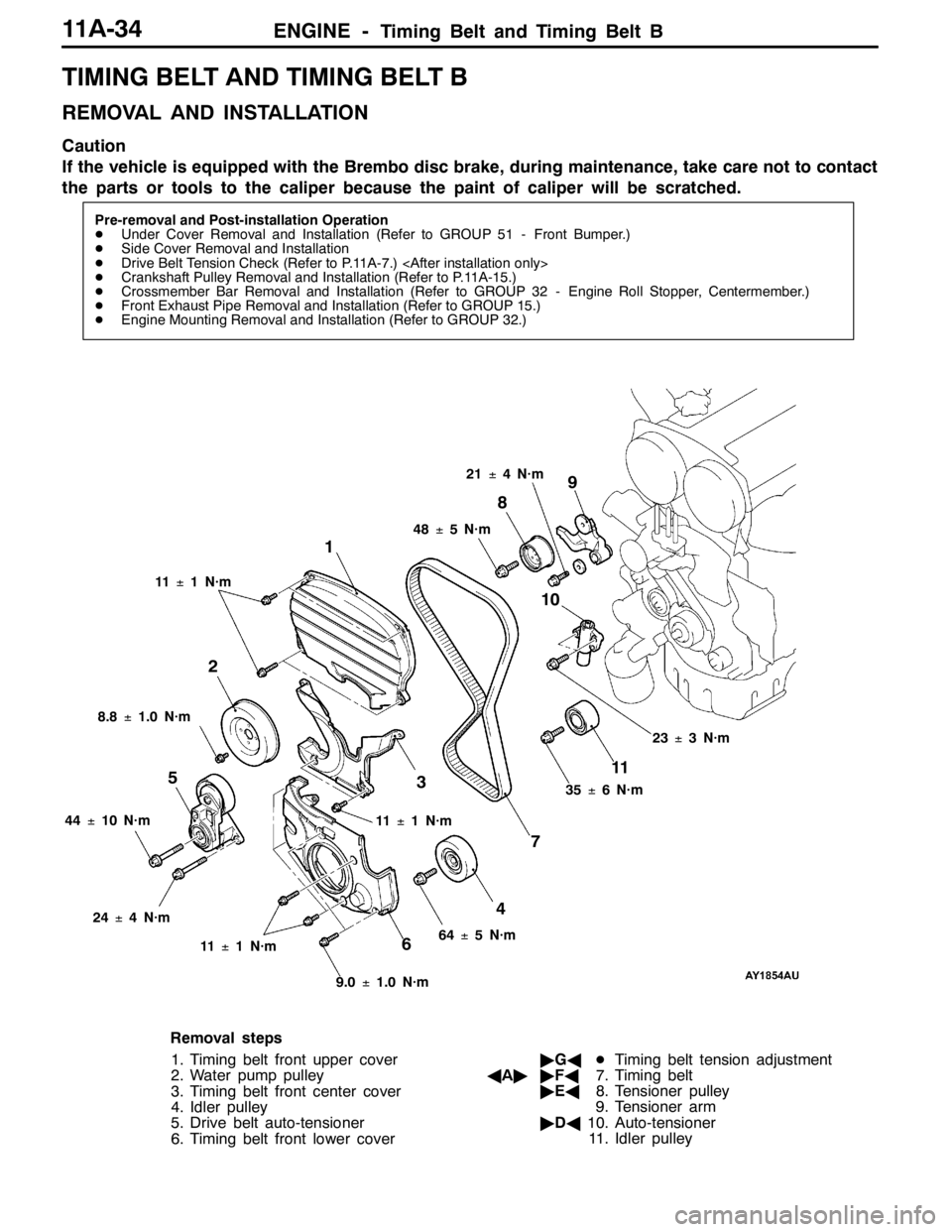
ENGINE -Timing Belt and Timing Belt B11A-34
TIMING BELT AND TIMING BELT B
REMOVAL AND INSTALLATION
Caution
If the vehicle is equipped with the Brembo disc brake, during maintenance, take care not to contact
the parts or tools to the caliper because the paint of caliper will be scratched.
Pre-removal and Post-installation Operation
DUnder Cover Removal and Installation (Refer to GROUP 51 - Front Bumper.)
DSide Cover Removal and Installation
DDrive Belt Tension Check (Refer to P.11A-7.)
DCrankshaft Pulley Removal and Installation (Refer to P.11A-15.)
DCrossmember Bar Removal and Installation (Refer to GROUP 32 - Engine Roll Stopper, Centermember.)
DFront Exhaust Pipe Removal and Installation (Refer to GROUP 15.)
DEngine Mounting Removal and Installation (Refer to GROUP 32.)
1
2
3
4 5
67 89
10
11±1 N·m
8.8±1.0 N·m
44±10 N·m
24±4 N·m
11±1 N·m
9.0±1.0 N·m64±5 N·m 11±1 N·m48±5 N·m21±4 N·m
23±3 N·m
11
35±6 N·m
Removal steps
1. Timing belt front upper cover
2. Water pump pulley
3. Timing belt front center cover
4. Idler pulley
5. Drive belt auto-tensioner
6. Timing belt front lower cover"GADTiming belt tension adjustment
AA""FA7. Timing belt
"EA8. Tensioner pulley
9. Tensioner arm
"DA10. Auto-tensioner
11. Idler pulley
Page 445 of 1449
ENGINE -Timing Belt and Timing Belt B11A-39
"FATIMING BELT INSTALLATION
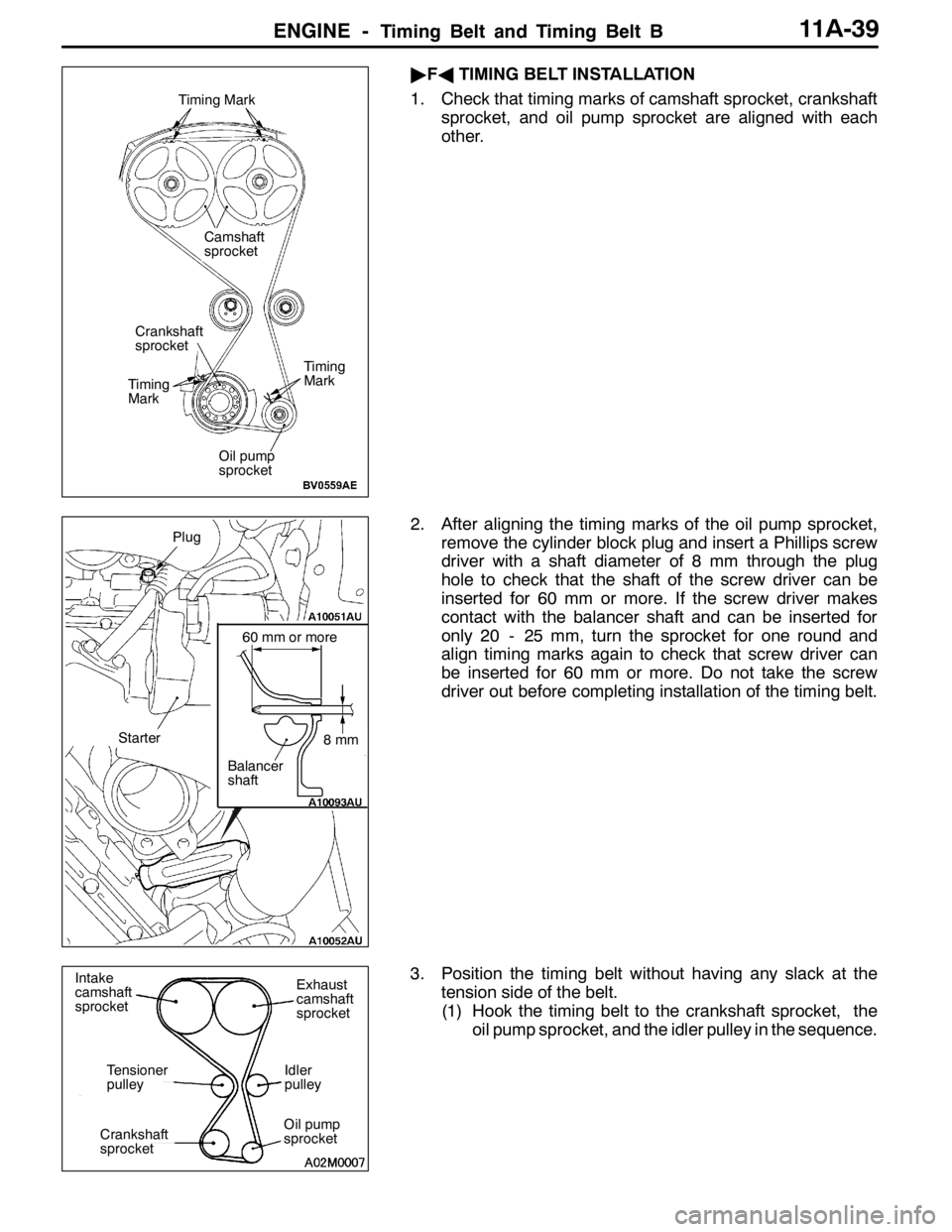
1. Check that timing marks of camshaft sprocket, crankshaft
sprocket, and oil pump sprocket are aligned with each
other.
2. After aligning the timing marks of the oil pump sprocket,
remove the cylinder block plug and insert a Phillips screw
driver with a shaft diameter of 8 mm through the plug
hole to check that the shaft of the screw driver can be
inserted for 60 mm or more. If the screw driver makes
contact with the balancer shaft and can be inserted for
only 20 - 25 mm, turn the sprocket for one round and
align timing marks again to check that screw driver can
be inserted for 60 mm or more. Do not take the screw
driver out before completing installation of the timing belt.
3. Position the timing belt without having any slack at the
tension side of the belt.
(1) Hook the timing belt to the crankshaft sprocket, the
oil pump sprocket, and the idler pulley in the sequence.
Timing Mark
Timing
Mark
Timing
Mark
Crankshaft
sprocket
Oil pump
sprocket
Camshaft
sprocket
8mm
60 mm or more
Balancer
shaft
Plug
Starter
Intake
camshaft
sprocketExhaust
camshaft
sprocket
Idler
pulley
Oil pump
sprocketCrankshaft
sprocket
Tensioner
pulley
Page 459 of 1449
ENGINE OVERHAUL -Specifications11B-5
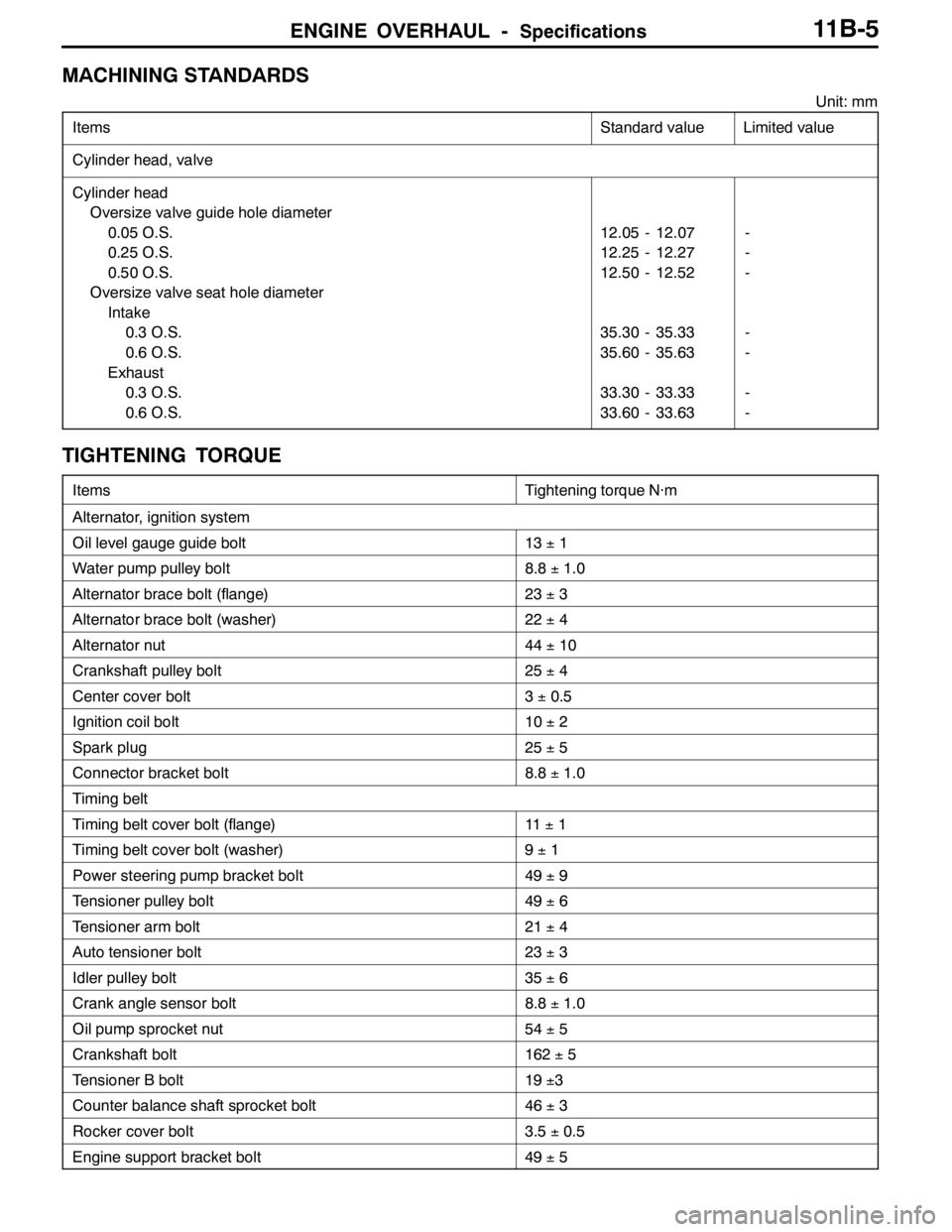
MACHINING STANDARDS
Unit: mm
Items
Standard valueLimited value
Cylinder head, valve
Cylinder head
Oversize valve guide hole diameter
0.05 O.S.
0.25 O.S.
0.50 O.S.
Oversize valve seat hole diameter
Intake
0.3 O.S.
0.6 O.S.
Exhaust
0.3 O.S.
0.6 O.S.
12.05 - 12.07
12.25 - 12.27
12.50 - 12.52
35.30 - 35.33
35.60 - 35.63
33.30 - 33.33
33.60 - 33.63-
-
-
-
-
-
-
TIGHTENING TORQUE
ItemsTightening torque N·m
Alternator, ignition system
Oil level gauge guide bolt13±1
Water pump pulley bolt8.8±1.0
Alternator brace bolt (flange)23±3
Alternator brace bolt (washer)22±4
Alternator nut44±10
Crankshaft pulley bolt25±4
Center cover bolt3±0.5
Ignition coil bolt10±2
Spark plug25±5
Connector bracket bolt8.8±1.0
Timing belt
Timing belt cover bolt (flange)11±1
Timing belt cover bolt (washer)9±1
Power steering pump bracket bolt49±9
Tensioner pulley bolt49±6
Tensioner arm bolt21±4
Auto tensioner bolt23±3
Idler pulley bolt35±6
Crank angle sensor bolt8.8±1.0
Oil pump sprocket nut54±5
Crankshaft bolt162±5
Tensioner B bolt19±3
Counter balance shaft sprocket bolt46±3
Rocker cover bolt3.5±0.5
Engine support bracket bolt49±5
Page 467 of 1449
ENGINE OVERHAUL -Timing Belt11B-13
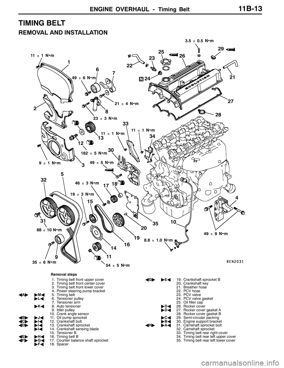
TIMING BELT
REMOVAL AND INSTALLATION
1
11±1N•m
2
3
4 56
7
8
910
11 1213
14 15
16 1718
192021 2223
2425
26
27
2829
30
313233
34
35
49±6N•m
21±4N•m
23±3N•m
11±1N•m11±1N•m
88±10 N•m
35±6N•m
54±5N•m 19±3N•m 46±3N•m 9±1N•m162±5N•m3.5±0.5 N•m
49±9N•m
8.8±1.0 N•m 49±5N•m
Removal steps
1. Timing belt front upper cover
2. Timing belt front center cover
3. Timing belt front lower cover
4. Power steering pump bracket
AA""MA5. Timing belt
"LA6. Tensioner pulley
7. Tensioner arm
"KA8. Auto tensioner
9. Idler pulley
10. Crank angle sensor
AB""JA11. Oil pump sprocket
AC""IA12. Crankshaft bolt
AD""IA13. Crankshaft sprocket
"IA14. Crankshaft sensing blade
15. Tensioner B
AE""HA16. Timing belt B
AF""GA17. Counter balance shaft sprocket
"FA18. SpacerAG""EA19. Crankshaft sprocket B
20. Crankshaft key
21. Breather hose
22. PCV hose
23. PCV valve
24. PCV valve gasket
25. Oil filler cap
"DA26. Rocker cover
"DA27. Rocker cover gasket A
28. Rocker cover gasket B
"CA29. Semi-circular packing
"BA30. Engine support bracket
AH""AA31. Camshaft sprocket bolt
32. Camshaft sprocket
33. Timing belt rear right cover
34. Timing belt rear left upper cover
35. Timing belt rear left lower cover
Page 476 of 1449
ENGINE OVERHAUL -Timing Belt11B-22
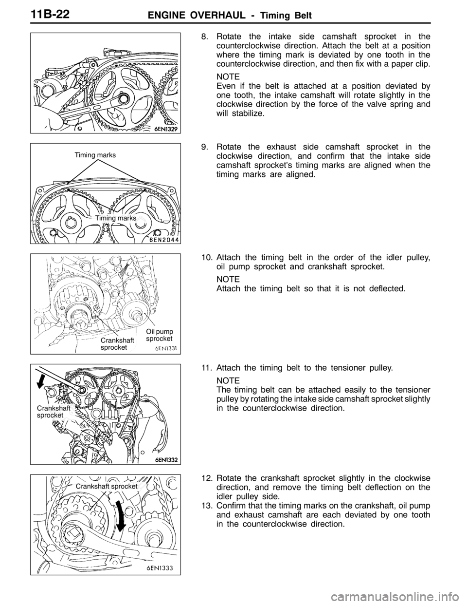
8. Rotate the intake side camshaft sprocket in the
counterclockwise direction. Attach the belt at a position
where the timing mark is deviated by one tooth in the
counterclockwise direction, and then fix with a paper clip.
NOTE
Even if the belt is attached at a position deviated by
one tooth, the intake camshaft will rotate slightly in the
clockwise direction by the force of the valve spring and
will stabilize.
9. Rotate the exhaust side camshaft sprocket in the
clockwise direction, and confirm that the intake side
camshaft sprocket’s timing marks are aligned when the
timing marks are aligned.
10. Attach the timing belt in the order of the idler pulley,
oil pump sprocket and crankshaft sprocket.
NOTE
Attach the timing belt so that it is not deflected.
11. Attach the timing belt to the tensioner pulley.
NOTE
The timing belt can be attached easily to the tensioner
pulley by rotating the intake side camshaft sprocket slightly
in the counterclockwise direction.
12. Rotate the crankshaft sprocket slightly in the clockwise
direction, and remove the timing belt deflection on the
idler pulley side.
13. Confirm that the timing marks on the crankshaft, oil pump
and exhaust camshaft are each deviated by one tooth
in the counterclockwise direction.
Timing marks Timing marks
Crankshaft
sprocketOil pump
sprocket
Crankshaft
sprocket
Crankshaft sprocket
Page 867 of 1449
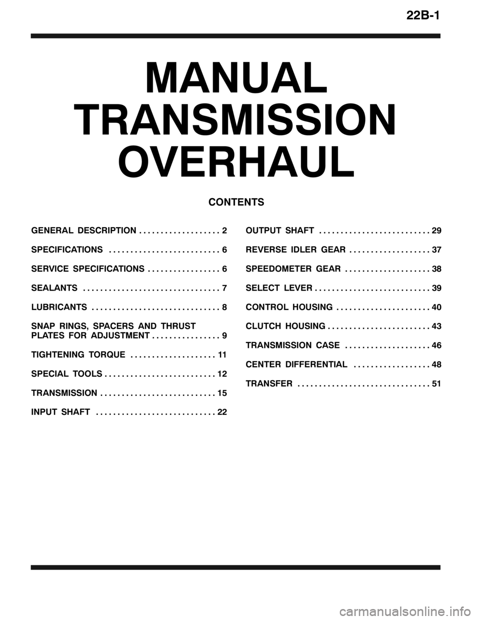
22B-1
MANUAL
TRANSMISSION
OVERHAUL
CONTENTS
GENERAL DESCRIPTION 2...................
SPECIFICATIONS 6..........................
SERVICE SPECIFICATIONS 6.................
SEALANTS 7................................
LUBRICANTS 8..............................
SNAP RINGS, SPACERS AND THRUST
PLATES FOR ADJUSTMENT 9................
TIGHTENING TORQUE 11....................
SPECIAL TOOLS 12..........................
TRANSMISSION 15...........................
INPUT SHAFT 22............................OUTPUT SHAFT 29..........................
REVERSE IDLER GEAR 37...................
SPEEDOMETER GEAR 38....................
SELECT LEVER 39...........................
CONTROL HOUSING 40......................
CLUTCH HOUSING 43........................
TRANSMISSION CASE 46....................
CENTER DIFFERENTIAL 48..................
TRANSFER 51...............................
Page 877 of 1449
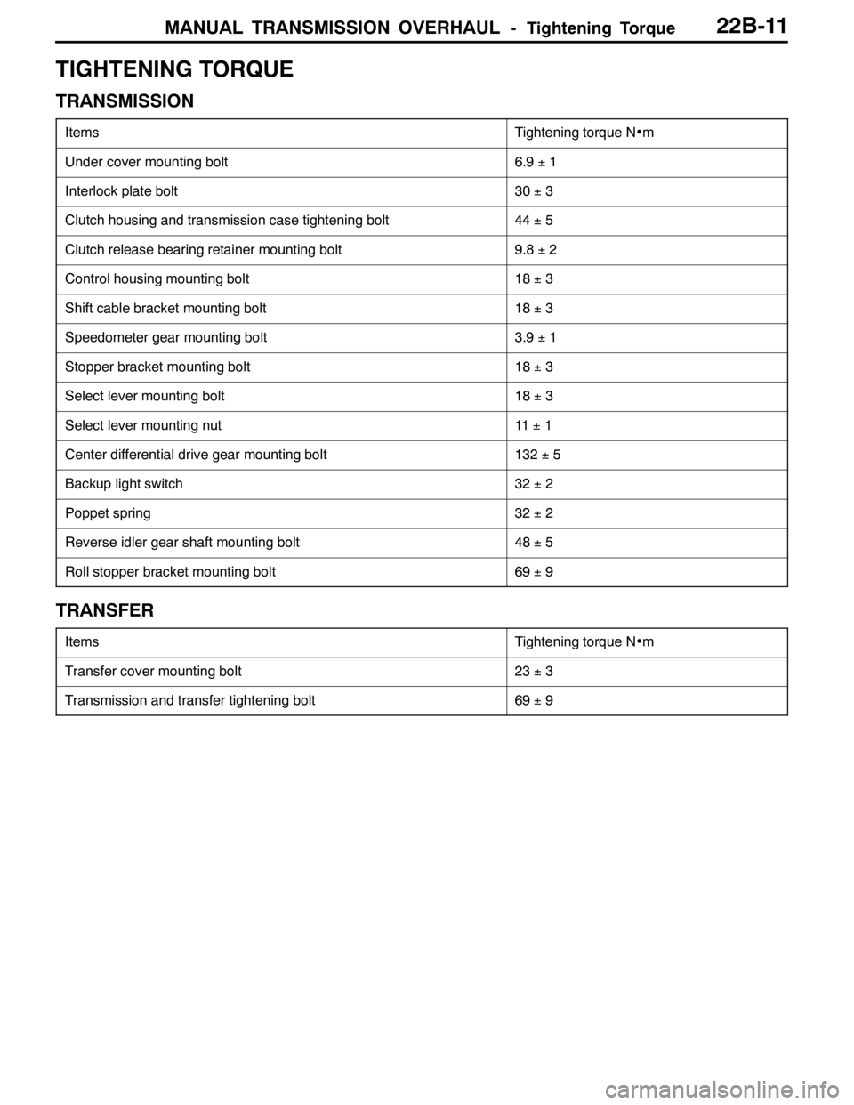
MANUAL TRANSMISSION OVERHAUL -Tightening Torque22B-11
TIGHTENING TORQUE
TRANSMISSION
ItemsTightening torque N•m
Under cover mounting bolt6.9±1
Interlock plate bolt30±3
Clutch housing and transmission case tightening bolt44±5
Clutch release bearing retainer mounting bolt9.8±2
Control housing mounting bolt18±3
Shift cable bracket mounting bolt18±3
Speedometer gear mounting bolt3.9±1
Stopper bracket mounting bolt18±3
Select lever mounting bolt18±3
Select lever mounting nut11±1
Center differential drive gear mounting bolt132±5
Backup light switch32±2
Poppet spring32±2
Reverse idler gear shaft mounting bolt48±5
Roll stopper bracket mounting bolt69±9
TRANSFER
ItemsTightening torque N•m
Transfer cover mounting bolt23±3
Transmission and transfer tightening bolt69±9
Page 882 of 1449
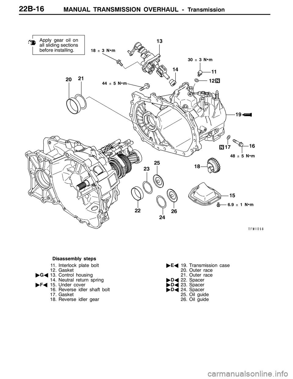
MANUAL TRANSMISSION OVERHAUL -Transmission22B-16
18±3N•m
6.9±1N•m 48±5N•m 30±3N•m
44±5N•m
20
Apply gear oil on
all sliding sections
before installing.
2113
14
11
12
19
1716
18
15 25
23
22
2426
Disassembly steps
11. Interlock plate bolt
12. Gasket
"GA13. Control housing
14. Neutral return spring
"FA15. Under cover
16. Reverse idler shaft bolt
17. Gasket
18. Reverse idler gear"EA19. Transmission case
20. Outer race
21. Outer race
"DA22. Spacer
"DA23. Spacer
"DA24. Spacer
25. Oil guide
26. Oil guide