2007 MITSUBISHI LANCER EVOLUTION oil change
[x] Cancel search: oil changePage 564 of 1449

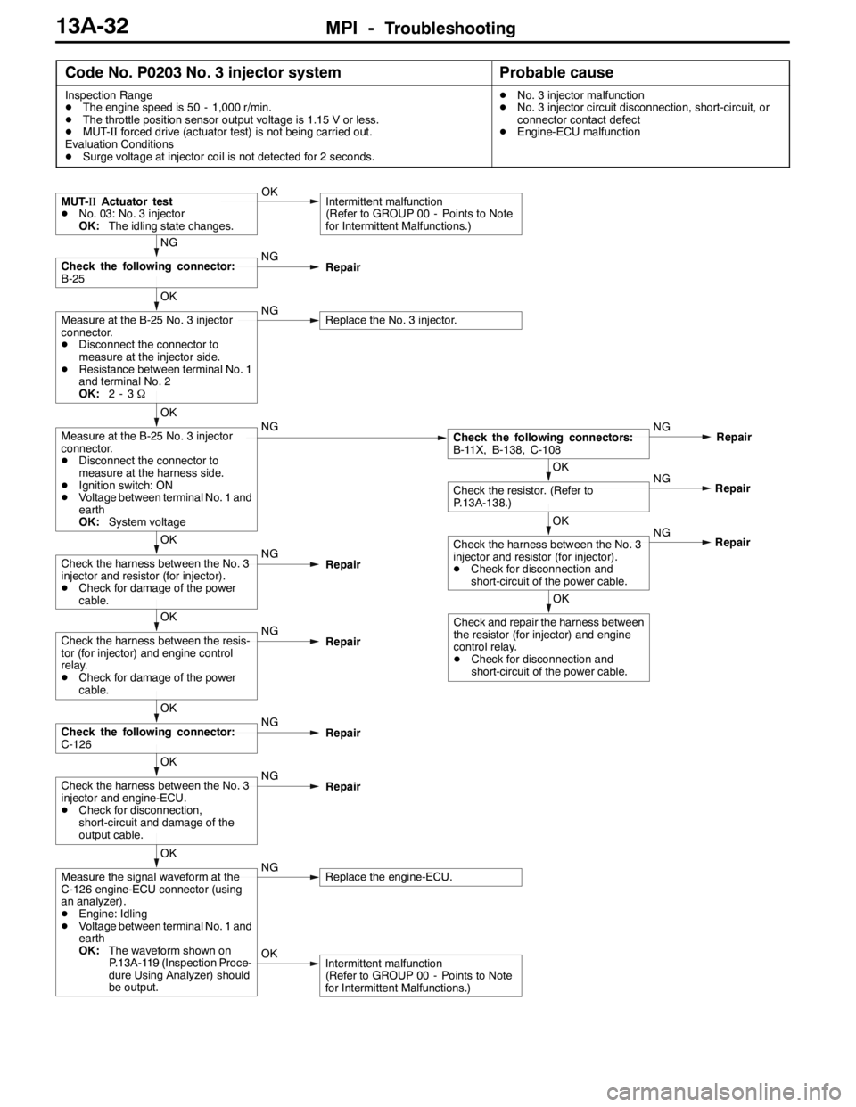
MPI -Troubleshooting13A-32
Code No. P0203 No. 3 injector systemProbable cause
Inspection Range
DThe engine speed is 50 - 1,000 r/min.
DThe throttle position sensor output voltage is 1.15 V or less.
DMUT-IIforced drive (actuator test) is not being carried out.
Evaluation Conditions
DSurge voltage at injector coil is not detected for 2 seconds.DNo. 3 injector malfunction
DNo. 3 injector circuit disconnection, short-circuit, or
connector contact defect
DEngine-ECU malfunction
OKIntermittent malfunction
(Refer to GROUP 00 - Points to Note
for Intermittent Malfunctions.)
OK
Measure the signal waveform at the
C-126 engine-ECU connector (using
an analyzer).
DEngine: Idling
DVoltage between terminal No. 1 and
earth
OK:The waveform shown on
P.13A-119 (Inspection Proce-
dure Using Analyzer) should
be output.NGReplace the engine-ECU.
OK
Check the harness between the No. 3
injector and engine-ECU.
DCheck for disconnection,
short-circuit and damage of the
output cable.NG
Repair
OK
Check the following connector:
C-126NG
Repair
OK
Check the harness between the resis-
tor (for injector) and engine control
relay.
DCheck for damage of the power
cable.NG
Repair
OK
Check and repair the harness between
the resistor (for injector) and engine
control relay.
DCheck for disconnection and
short-circuit of the power cable.NG
OK
Check the harness between the No. 3
injector and resistor (for injector).
DCheck for disconnection and
short-circuit of the power cable.Repair NG
OK
Check the resistor. (Refer to
P.13A-138.)Repair
OK
Check the harness between the No. 3
injector and resistor (for injector).
DCheck for damage of the power
cable.NG
Repair
OK
Measure at the B-25 No. 3 injector
connector.
DDisconnect the connector to
measure at the harness side.
DIgnition switch: ON
DVoltage between terminal No. 1 and
earth
OK:System voltageNGCheck the following connectors:
B-11X, B-138, C-108NG
Repair
OK
Measure at the B-25 No. 3 injector
connector.
DDisconnect the connector to
measure at the injector side.
DResistance between terminal No. 1
and terminal No. 2
OK:2-3ΩNGReplace the No. 3 injector.
NG
Check the following connector:
B-25NG
Repair
MUT-IIActuator test
DNo. 03: No. 3 injector
OK:The idling state changes.OKIntermittent malfunction
(Refer to GROUP 00 - Points to Note
for Intermittent Malfunctions.)
Page 565 of 1449

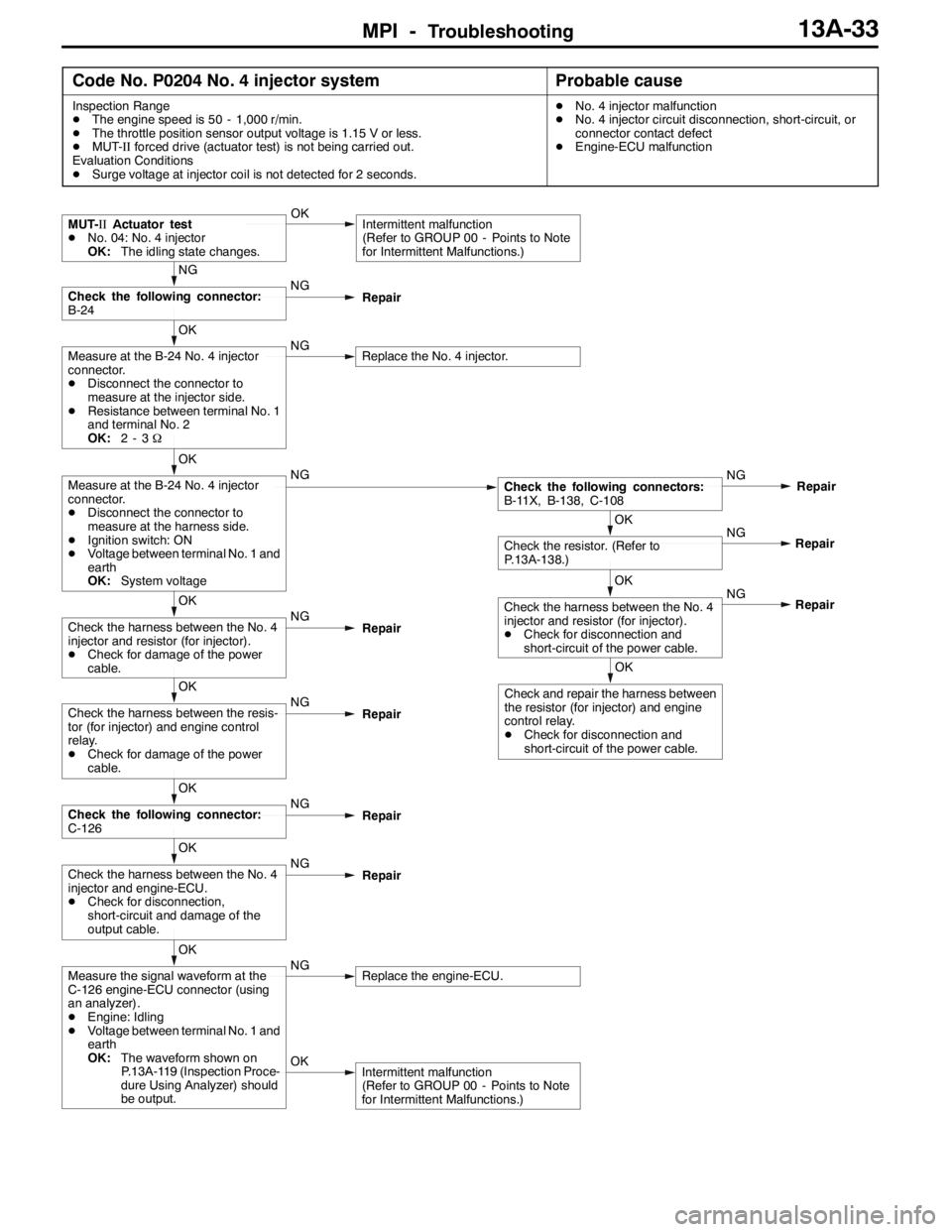
MPI -Troubleshooting13A-33
Code No. P0204 No. 4 injector systemProbable cause
Inspection Range
DThe engine speed is 50 - 1,000 r/min.
DThe throttle position sensor output voltage is 1.15 V or less.
DMUT-IIforced drive (actuator test) is not being carried out.
Evaluation Conditions
DSurge voltage at injector coil is not detected for 2 seconds.DNo. 4 injector malfunction
DNo. 4 injector circuit disconnection, short-circuit, or
connector contact defect
DEngine-ECU malfunction
OKIntermittent malfunction
(Refer to GROUP 00 - Points to Note
for Intermittent Malfunctions.)
OK
Measure the signal waveform at the
C-126 engine-ECU connector (using
an analyzer).
DEngine: Idling
DVoltage between terminal No. 1 and
earth
OK:The waveform shown on
P.13A-119 (Inspection Proce-
dure Using Analyzer) should
be output.NGReplace the engine-ECU.
OK
Check the harness between the No. 4
injector and engine-ECU.
DCheck for disconnection,
short-circuit and damage of the
output cable.NG
Repair
OK
Check the following connector:
C-126NG
Repair
OK
Check the harness between the resis-
tor (for injector) and engine control
relay.
DCheck for damage of the power
cable.NG
Repair
OK
Check and repair the harness between
the resistor (for injector) and engine
control relay.
DCheck for disconnection and
short-circuit of the power cable.NG
OK
Check the harness between the No. 4
injector and resistor (for injector).
DCheck for disconnection and
short-circuit of the power cable.Repair NG
OK
Check the resistor. (Refer to
P.13A-138.)Repair
OK
Check the harness between the No. 4
injector and resistor (for injector).
DCheck for damage of the power
cable.NG
Repair
OK
Measure at the B-24 No. 4 injector
connector.
DDisconnect the connector to
measure at the harness side.
DIgnition switch: ON
DVoltage between terminal No. 1 and
earth
OK:System voltageNGCheck the following connectors:
B-11X, B-138, C-108NG
Repair
OK
Measure at the B-24 No. 4 injector
connector.
DDisconnect the connector to
measure at the injector side.
DResistance between terminal No. 1
and terminal No. 2
OK:2-3ΩNGReplace the No. 4 injector.
NG
Check the following connector:
B-24NG
Repair
MUT-IIActuator test
DNo. 04: No. 4 injector
OK:The idling state changes.OKIntermittent malfunction
(Refer to GROUP 00 - Points to Note
for Intermittent Malfunctions.)
Page 641 of 1449

MPI -TroubleshootingMPI -Troubleshooting13A-109
Engine-ECU Connector Terminal Arrangement
Terminal No.Check itemCheck condition (Engine condition)Normal condition
1No. 1 injectorWhile engine is idling after having warmed up,
suddenlydepresstheacceleratorpedal
From 11 - 14 V, momentarily
dropsslightly
14No. 2 injector
suddenlydepressthe accelerator pedal.drops slightly
2No. 3 injector
15No. 4 injector
3Fuel pressure control
solenoidvalve
Ignition switch: “ON”System voltage
solenoidvalve
Engine: Cranking→Idle operation
(within approximately 2 minutes or less)1 V or less→System voltage
4Stepper motor coil
startedSystem voltage↔0-6V
(Changes repeatedly)
17Stepper motor coil
5Stepper motor coil
18Stepper motor coil
6EGR control solenoid
valve
Ignition switch: “ON”System Voltage
valve
While engine is idling, suddenly depress the
accelerator pedal.From system voltage,
momentarily drops
8A/C relayDEngine: Idle operation
DA/Cswitch:OFF→ON(A/Ccompressor
System voltage or momen-
tarily6Vormore→1VorDA/Cswitch:OFF→ON(A/Ccompressor
runs)tarily6Vor more→1Vor
less
9Purge control sole-
noidvalve
Ignition switch: “ON”System voltage
noidvalve
Engine: Idle operation1 V or less
10Ignition coil - No.1,
No.4Engine speed: 3,000 r/min0.3 - 3.0 V
23Ignition coil - No.2,
No.3
11Waste gate solenoid
valve
Ignition switch: “ON”System voltage
valve
Engine: After warm-up, idle operation
(When using premium gasoline)1 V or less
Page 662 of 1449

MPI -On-vehicle Service13A-130
14. If any of fuel pressure measured in steps 10 to 13 is out of
specification, troubleshoot and repair according to the
table below.
SymptomProbable causeRemedy
DFuel pressure too low
DFuelpressuredropsafterracing
Clogged fuel filterReplace fuel filter
DFuelpressuredrops after racing
DNo fuel pressure in fuel return
hose
Fuel leaking to return side due to poor
fuel regulator valve seating or settled
springReplace fuel pressure regulator
Low fuel pump delivery pressureReplace fuel pump
Fuel pressure too highBinding valve in fuel pressure
regulatorReplace fuel pressure regulator
Clogged fuel return hose or pipeClean or replace hose or pipe
Same fuel pressure when vacuum
hose is connected and when
disconnected
Damaged vacuum hose or clogged
nippleReplace vacuum hose or clean nipple
disconnectedFuel pressure control system
malfunctionCheck the fuel pressure control
system
15. Stop the engine and check change of fuel pressure gauge
reading. Normal if the reading does not drop within 2
minutes. If it does, observe the rate of drop and
troubleshoot and repair according to the table below.
SymptomProbable causeRemedy
Fuel pressure drops gradually after
engineisstopped
Leaky injectorReplace injector
engineisstopped
Leaky fuel regulator valve seatReplace fuel pressure regulator
Fuel pressure drops sharply
immediately after engine is stoppedCheck valve in fuel pump is held openReplace fuel pump
16. Release residual pressure from the fuel pipe line.
(Refer to P.13A-125.)
17. Remove the fuel pressure gauge and special tool from
the delivery pipe.
Caution
Cover the hose connection with rags to prevent splash
of fuel that could be caused by some residual pressure
in the fuel pipe line.
18. Replace the O-ring at the end of the fuel high pressure
hose with a new one. Furthermore, apply engine oil to
the new O-ring before replacement.
19. Fit the fuel high pressure hose over the delivery pipe
and tighten the bolt to specified torque.
Tightening torque: 5.0±1.0 N·m
20. Check for any fuel leaks by following the procedure in
step 7.
21. Disconnect the MUT-II.
Page 810 of 1449

22A-2
MANUAL
TRANSMISSION
CONTENTS
GENERAL 3.................................
Outline of Changes 3...........................
GENERAL INFORMATION 3..................
SERVICE SPECIFICATION 3..................
LUBRICANTS 3..............................
SPECIAL TOOLS 4...........................
TROUBLESHOOTING
ON-VEHICLE SERVICE 40....................
Transmission Oil Check 40......................
Transmission Oil Replacement 40................
Transfer Oil Check 40..........................
Transfer Oil Replacement 40....................
Fluid Check
Bleeding
Hydraulic Pressure Check
Wheel Speed Sensor Output Voltage
Measurement
TRANSMISSION CONTROL* 46...............
TRANSFER ASSEMBLY 49...................
TRANSMISSION ASSEMBLY 52...............
4WD-ECU
SENSOR, SWITCH AND RELAY
AYC> 56.....................................
HYDRAULIC UNIT Refer to GROUP27B.......
WARNING REGARDING SERVICING OF SUPPLEMENTAL RESTRAINT SYSTEM (SRS) EQUIPPED VEHICLES
WARNING!
(1) Improper service or maintenance of any component of the SRS, or any SRS-related component, can lead to personal
injury or death to service personnel (from inadvertent firing of the air bag) or to driver and passenger (from rendering
the SRS inoperative).
(2) Service or maintenance of any SRS component or SRS-related component must be performed only at an authorized
MITSUBISHI dealer.
(3) MITSUBISHI dealer personnel must thoroughly review this manual, and especially its GROUP 52B - Supplemental
Restraint System (SRS) before beginning any service or maintenance of any component of the SRS or any SRS-related
component.
NOTE
The SRS includes the following components: SRS-ECU, SRS warning lamp, air bag module, clock spring, and interconnecting
wiring. Other SRS-related components (that may have to be removed/installed in connection with SRS service or maintenance) are
indicated in the table of contents by an asterisk (*).
Page 811 of 1449

MANUAL TRANSMISSION -General/General Information/
Service Specification/Lubricants22A-3
GENERAL
OUTLINE OF CHANGE
With the addition of the EVOLUTION-VII, the W5M51 transmission service adjustment procedure has
been set as follows.
GENERAL INFORMATION
ItemsSpecifications
GradeRS, RS IIRS, RS II (With super cross gear)
Transmission modelW5M51
Engine model4G63-DOHC-T/C
Type5-speed, floor-shift
Gear ratio1st2.7852.785
2nd1.9501.950
3rd1.4071.444
4th1.0311.096
5th0.7200.825
Reverse3.4163.416
Final reduction ratio
(Differential gear ratio)4.5294.529
Front limited-slip differential
(Helical-gear type)Not providedProvided
TransferReduction ratio3.3073.307
Limited-slipdifferentialVCU or hydraulic multi plate
clutch (ACD)VCU or hydraulic multi plate
clutch (ACD)
SERVICE SPECIFICATION
ItemStandard value
Hydraulic unit generation oil pressureMPa1.0 - 1.6
LUBRICANTS
ItemSpecified lubricantQuantity L
Transmission oilGear oil SAE 75W-90 or 75W-85W conforming to API GL-42.8
Transfer
oilVehicles without ACD or ve-
hicles without ACD and AYCMITSUBISHI Genuine Gear Oil Part No.8149630 EX,
CASTROL HYPOY LS (GL-5, SAE 90), SHELL-LSD
(GL 5SAE80W90)orequivalent
0.55
Vehicles with ACD or vehicles
with ACD and AYC(GL-5, SAE 80W - 90) or equivalent0.6
FluidPiping between ACD and
hydraulic unitDIA QUEEN ATF SP III0.9
Pipes between ACD and hy-
draulic unit and between AYC
and hydraulic unit1.0
Page 947 of 1449

27B-1
REAR AXLE
CONTENTS
GENERAL INFORMATION 2...................
SERVICE SPECIFICATIONS 3.................
LUBRICANTS 3..............................
SEALANTS 4................................
SPECIAL TOOLS 4...........................
TROUBLESHOOTING (AYC) 8.................
ON-VEHICLE SERVICE 16....................
Rear Axle Total Backlash Check 16...............
Gear Oil Level Check 16........................
Gear Oil Change 17............................
Fluid Level Check 19............................
Bleeding 19....................................
AYC Operation Check 20........................
Oil Pressure Check 21..........................Wheel Bearing Axial Play Check 22...............
Wheel Bearing Rotary-sliding Resistance Check 22.
Hub Bolt Replacement 23.......................
Differential Carrier Oil Seal Replacement 23........
Action When Battery Runs Out 24................
REAR HUB ASSEMBLY 25....................
KNUCKLE 28................................
DRIVE SHAFT 29.............................
DIFFERENTIAL CARRIER
DIFFERENTIAL CARRIER
HYDRAULIC UNIT
Page 963 of 1449

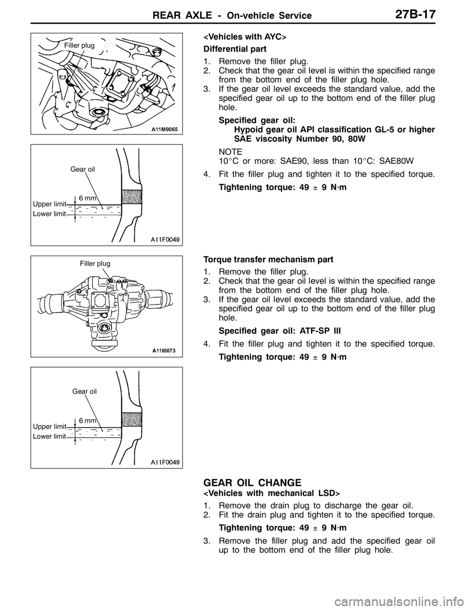
REAR AXLE -On-vehicle Service27B-17
Differential part
1. Remove the filler plug.
2. Check that the gear oil level is within the specified range
from the bottom end of the filler plug hole.
3. If the gear oil level exceeds the standard value, add the
specified gear oil up to the bottom end of the filler plug
hole.
Specified gear oil:
Hypoid gear oil API classification GL-5 or higher
SAE viscosity Number 90, 80W
NOTE
10_C or more: SAE90, less than 10_C: SAE80W
4. Fit the filler plug and tighten it to the specified torque.
Tightening torque: 49±9 N·m
Torque transfer mechanism part
1. Remove the filler plug.
2. Check that the gear oil level is within the specified range
from the bottom end of the filler plug hole.
3. If the gear oil level exceeds the standard value, add the
specified gear oil up to the bottom end of the filler plug
hole.
Specified gear oil: ATF-SP III
4. Fit the filler plug and tighten it to the specified torque.
Tightening torque: 49±9 N·m
GEAR OIL CHANGE
1. Remove the drain plug to discharge the gear oil.
2. Fit the drain plug and tighten it to the specified torque.
Tightening torque: 49±9 N·m
3. Remove the filler plug and add the specified gear oil
up to the bottom end of the filler plug hole.
Filler plug
Upper limit
Lower limitGear oil
6mm
Filler plug
Upper limit
Lower limitGear oil
6mm